Exchange bias effect in cylindrical nanowires
with ferromagnetic core and polycrystalline antiferromagnetic shell
Abstract
We model the exchange bias effect in thin cylindrical nanowires composed of a ferromagnetic core and an antiferromagnetic shell implementing a classical spin Hamiltonian and Monte Carlo simulations. We address systematically the effect of shell polycrystallinity on the characteristic fields of the isothermal hysteresis loop (coercivity, exchange-bias) and their angular dependence upon the direction of the applied / cooling field. We relate the observed trends to modifications of the underlying magnetization reversal mechanism. We fit our simulation results to an extended Stoner-Wohlfarth model with effective off-axis unidirectional anisotropy and demonstrate that shell polycrystallinity could lead to maximum exchange bias effect in an off-axis direction. Our results are in qualitative agreement with recent experimental studies of Co/CoO nanowires.
pacs:
75.60.Jk; 75.75.Jn; 75.75.Fk; 75.78.FgI Introduction
Tailoring the magnetic properties at the nanoscale has attracted great research interest in recent years, due to the plethora of prospective applicationsSkomski (2003). Advances in template-assisted electrodepositionFert and Piraux (1999) enhanced substantially the research effort in quasi-one dimensional nanostructures, such as nanowires and nanotubes. These systems are characterized by enhanced shape anisotropy, which renders them prominent candidate materials for advanced technologies ranging from magnetic recordingSellmeyer et al. (2001) to biomedicineBauer et al. (2004); Tartaj (2006). On the other hand, the quasi-one dimensional geometry is ideal for efficient manipulation of magnetic solitonic excitations, such as domain walls, with potential applications to 3D magnetic memoryParkin et al. (2008). The magnetization reversal process lies in the heart of research related to magnetic nanowires. Their quasi one-dimensional shape leads to a complex reversal mechanism, consisted of domain wall (DW) nucleation, propagation and annihilationFert and Piraux (1999); Sellmeyer et al. (2001); Thiaville and Nakatani (2006). Furthermore, it has been demonstrated that the magnetization reversal mechanism and concomitant anisotropy can be tailored by alloying Bran et al. (2015), by periodic chemical modulation as in multisegmented nanowires Berganza et al. (2017) and by morphological modulations, as in diamater-modulated nanowiresPalmero et al. (2015).
In an alternative route to tailoring of the magnetic anisotropy of magnetic nanostructures, the exchange bias (EB) effectMeiklejohn and Bean (1956, 1957) has been extensively studied in nanostructures with a ferromagnetic (FM) core - antiferromagnetic (AF) shell morphologyNogués et al. (2005); Iglesias et al. (2008). Hysteresis loops of such systems exhibit a characteristic shift after been field-cooled, usually accompanied by magnetic hardening. Materials presenting these properties are currently implemented in spintronics applications, like spin-valves and magnetic tunnel junctionsKools (1996). Elongated nanostructures such as nanowiresMaurer et al. (2009); Tripathy et al. (2010); Gandha et al. (2017) and nanotubesBuchter et al. (2015); Proenca et al. (2013) with FM core - AF shell morphology have also been experimentally investigated showing exchange-bias and the accompanying effects. Maurer et alMaurer et al. (2009) compared the hysteresis properties of cylindrical Co and Co/CoO nanowires and demonstrated the suppression of the coercive field due to surface oxidation as well as an anomalous temperature dependence, which was attributed to the thermal fluctuations of the oxide shell. In a search for optimum applied field direction for enhancement of the EB effect, Tripathy et alTripathy et al. (2010) investigated the angular dependence of the EB field of lithographically grown Co/CoO nanowires and demonstrated the increase of the EB field in off-axis directions due to competing unidirectional and uniaxial (shape) anisotropies. Gandha et alGandha et al. (2017) reported giant EB effect in electodeposited Co/CoO nanowires with monocrystalline core and polycrystalline shell and enhancement of the EB effect in an off-axis direction relative to the nanowire axis.
Due to the crucial role played by the FM-AF interface spin structure in the EB effectNogués et al. (2005) a realistic description of the structure and dynamics of the AF layer is necessary. In a previous workPatsopoulos and Kechrakos (2017), we studied uniaxial FM core/AF shell nanowires in order to study the impact of the AF shell on the loop characteristics and in the magnetization reversal mechanism. We showed that the interface exchange coupling produces a weak exchange-bias field and a suppression of coercivity relative to the bare FM nanowire. This behavior was attributed to the presence of unsatisfied FM-AF interface bonds that act as a sequence of nucleation centers leading to a secondary reversal mechanism that acts in synergy to domain wall propagation and eventually to mobility enhancement. However, Co/CoO nanowires prepared by surface oxidation of electodeposited Co nanowires develop a polycrystalline shellGandha et al. (2017).
The effect of shell granularity in FM/AF bilayers has been recently studied experimentallyChang et al. (2017) for Co/CoO bilayers and it was shown to cause enhancement of the EB field. However, to the best of our knowledge, a study of the effect of shell granularity on the the coercivity, the EB field and their angular dependence in the case of FM-AF core-shell nanowires has not been addressed yet.
In the present work, we implement the Monte Carlo method to study the effects of shell granularity on the EB behavior of cylindrical nanowires composed of a monocrystalline Co core and polycrystalline CoO shell. Shell granularity is shown to soften the magnetic anisotropy of the shell leading to enhancement of coercivity and suppression of the EB field. Additionally, shell granularity is shown to produce a monotonous drop of the coercive field and a non-monotonous drop of the EB field. The appearance of an optimum EB value is interpreted as an effective off-axis uniaxial anisotropy in the framework of a mesoscopic Stoner-Wohlfarth (SW) model. Finally, we compare our model predictions to recently reported measurements of the EB effect in Co/CoO nanowiresGandha et al. (2017).
II Model and Simulation Method
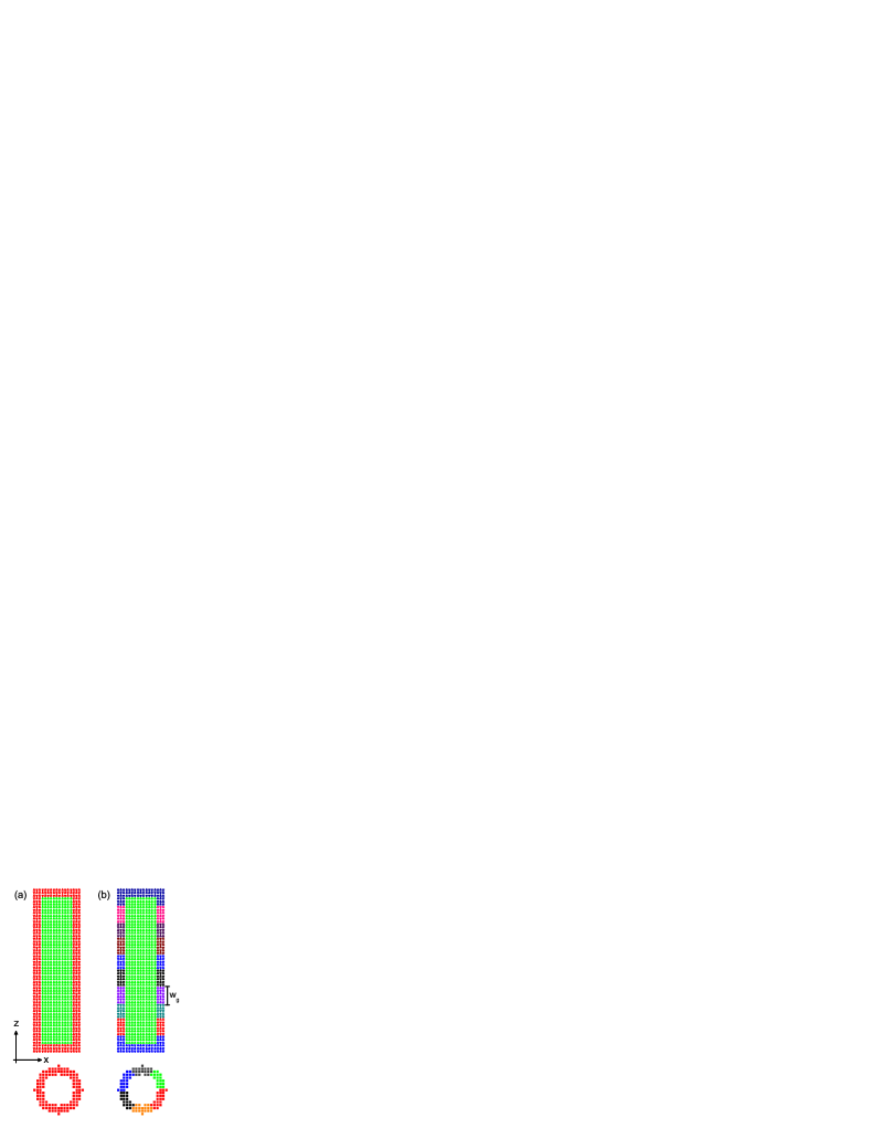
Nanowires are generated by cutting a cylinder along the z-axis with radius and length from an auxiliary simple cubic lattice with constant . For the core-shell morphology we define an internal homoaxial cylinder with radius and length , where is the shell thickness. We approximate the shell polycrystallinity (granularity) by dividing the shell in cylindrical slices along the z-axis and each slice in circular sectors. Thus, the shell is divided in identical crystallites (grains) with width , as seen in Fig. 1. The total energy of the magnetic system is , where the single-site energy term reads
| (1) |
In Eq. 1, hats indicate unit vectors and bold symbols matrices in Cartesian coordinates. The prefactor in the first and fourth terms in Eq. 1 accounts for the double-counting of the energy contribution from each site-pair (bond). The first term in Eq. 1 is the exchange energy between first nearest neighbors (1nn) sites. The exchange constant takes the values , and depending on whether sites and belong to the FM, the AF or the interface region, respectively. The latter contains the sites of the core (shell) having exchange bonds with sites in the shell (core). For 1nn exchange couplings, the interface region has width and consists of the core-interface layer and the shell-interface layer. The second term in Eq. 1 is the uniaxial anisotropy energy. The easy axes of the core sites are taken along the cylinder axis. Shell sites belonging to the same grain have a common easy axis, which, however, varies at random between different grains. The anisotropy constant takes the values and depending on the location of site . The third term in Eq. 1 is the Zeeman energy due to the applied field and the fourth term is the dipolar energy with strength . For computational efficiency, the dipolar energy term is treated in an embedded cluster approximation with a cluster radius Patsopoulos and Kechrakos (2017).
To observe the EB effect the nanowires are field-cooled (FC) from a high temperature to a low temperature under a field well below the saturation value of the AF phase . At the end of the FC process the external field is swept at a constant rate to obtain the isothermal hysteresis loop. The effective coercivity of the system is then defined as and the EB field as , where and are the coercive fields corresponding to the descending (ie. against the cooling field direction) and the ascending branch of the loop, respectively.
The FC process is simulated using the Metropolis Monte Carlo algorithm with single-spin updates and a temperature-dependent spin-cone aperture that accelerates the approach to equilibriumNewman and Barkema (1999) . The isothermal hysteresis is simulated using the same algorithm, but with a fixed spin-cone aperture () Thermal relaxation at each -point is done with Monte Carlo steps per spin (MCSS) for thermalization followed by MCSS for calculations of thermodynamic quantities. The latter are calculated every MCSS to minimize statistical correlations of the sampling points. The results at each -point are averaged over independent relaxation sequences. For systems with structural disorder, as the nanowires with granular shells, an average over samples with different realizations of disorder is performed.
In Eq. 1 we use dimensionless energy parameters scaled by , which is arbitrarily taken as , and = -0.5, = -0.5, = 0.1, = 1.0 and . These parameters capture the main features of the Co/CoO exchange coupled system as previous studies of oxide-coated cobalt nanoparticles Iglesias et al. (2008); Dimitriadis et al. (2015) and nanowiresPatsopoulos and Kechrakos (2017) have shown. Temperature and the magnetic field strength are measured in units of . Field-cooling is performed from high temperature to low temperature under an applied field with constant cooling rate MCSS. The field sweep rate is also kept constant at MCSS to exclude variation of results with sampling time.
III Results and Discussion
III.1 Isothermal hysteresis loops
We study first the macroscopic magnetic behavior of the nanowires, by calculating the low-temperature hysteresis loops and the characteristic fields of the loop, namely the coercivity () and the exchange-bias (), when the cooling and reversing fields are applied along the cylinder axis (z-axis). Different structural models of the AF shell are considered, as summarized in Table 1. In the limiting case of a monocrystalline shell (MS) a single shell grain exists, while in the other extreme case of a random shell (RS) each shell grain contains a single site . In the intermediate case of a polycrystalline shell (PS-60), the shell contains grains. Correspondingly, the size of the shell grains is maximum in the monocrystalline sample and minimum in the random sample.
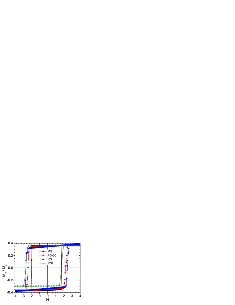
In Fig. 2 we compare the loops of nanowires with the same length, diameter and shell thickness, but different degree of shell crystallinity. The loop of a random shell with frozen spins (RSf) during field sweep is also included. A clear horizontal shift of the loops is observed in all samples as the outcome of the FC process. An overall feature seen is the gradual shearing of the loop as the size of the grains decreases, which is related to the fact that in nanowires with many grains and many easy axes in the shell, there exists a wider distribution of energy barriers to the reversal of the core interface moments. Furthermore, it becomes clear by simple inspection of Fig. 2 that the loops widen while their shift decreases with decreasing grain size, which directly implies an increase of coercivity and decrease of the exchange-bias field in nanowires with small grains. Our numerical results for and for different structural models used in the present work are summarized in Table 1.
| System | |||||
|---|---|---|---|---|---|
| MS | 56.0 | 1.82 | -0.14 | 0.015 | 0.0140 |
| PS-60 | 5.6 | 2.30 | -0.11 | 0.052 | 0.0120 |
| RS | 1.0 | 2.54 | -0.10 | 0.054 | 0.0085 |
| RSf | 1.0 | 2.18 | -0.49 | 0.054 | 0.0099 |
=shell grain size; =shell-interface magnetization (per spin) at the FC state; =domain wall mobility (a/MCSS);
The physical origin of the observed dependence of and on the grain size can be attributed to two distinct physical factors, namely the response of the shell-interface magnetization () to the applied field and the actual value of at the FC state.
To explain this point further, we show first in Fig. 3 the magnetization of the shell-interface layer as the applied field is swept. The observed expansion of the hysteresis loop with decreasing grain size indicates that the shell-interface spins are dragged by the core spins, via their mutual exchange coupling (). The magnetization drag mechanism becomes more efficient as the size of the grains decreases.
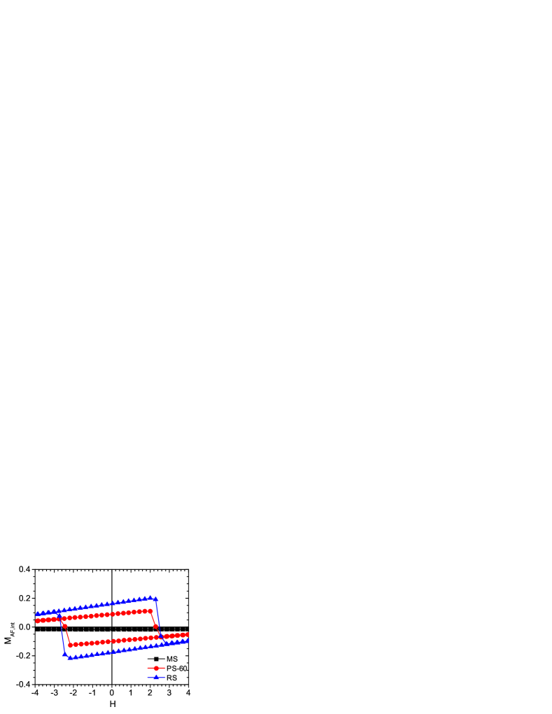
The exclusive impact of the drag mechanism on and can be deduced by comparison of the RS and the RSf nanowires that have identical AF spin structures at the FC state (i.e. values), but for the latter the shell moments are held frozen in their FC directions during the field sweep. As seen in Table 1 for these nanowires, is suppressed and is dramatically enhanced when the magnetization drag is switched off.
Second, the role of is revealed if one compares the MS and RSf nanowires, that have very different FC states (see Fig. 4), however, for both these systems the shell-interface moments remain frozen during field sweep. In the case of the MS nanowire, freezing of the shell-interface moments is dictated by the strong uniaxial anisotropy of the AF shell, as can be deduced from the insensitivity of shell magnetization to the applied field (Fig. 3). For RSf nanowires the shell moments are kept frozen during the simulation. The relative data in Table 1 show increased value of for the RSf system which is accompanied by enhancement of both and . We mention that this result is in accordance to the predictions of the Meiklejohn-Bean model that the bias-field varies linearly with the AF momentNogués and Schuller (1999). Overall, we conclude that the AF magnetization drag effect and the net interface moment of the AF shell act in synergy to enhance , while they act in competition to suppress .
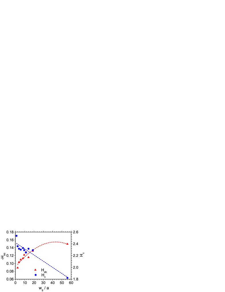
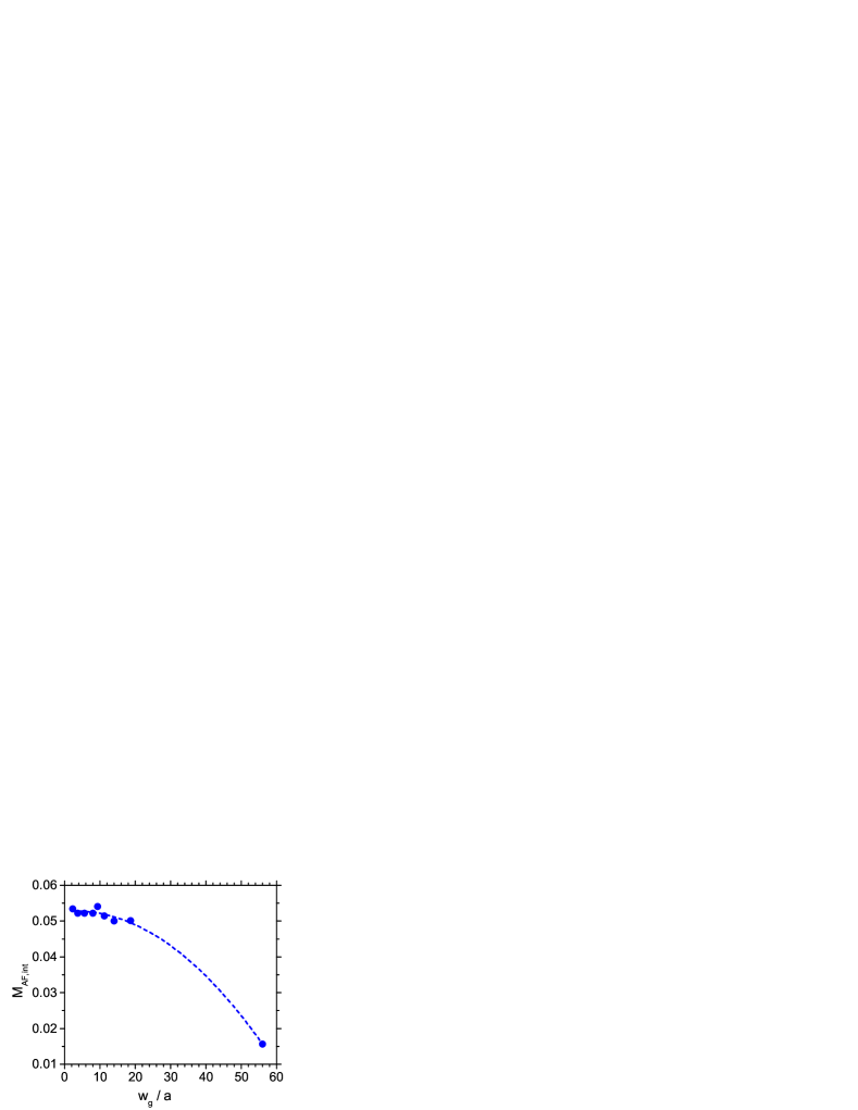
In Fig. 5 we show the dependence of the characteristic fields on grain size. In all cases the central angle of the grains is kept constant and only the width of the grains varies. We consider this is a reasonable approximation, because the nanowires studied here are thin and support transverse walls with almost coherent in-plane spin structurePatsopoulos and Kechrakos (2017). Thus, further reduction of the grain angle, leading to increase of values, did not modify our results. A systematic trend is seen in all cases, namely as the grain size is reduced, increases and decreases. This trend can be understood in the framework of the random anisotropy modelHerzer (1990), where reduction of the grain size leads to an effective anisotropy of the AF shell that is an average value over several grains within the range of the exchange correlation length and thus reduced in magnitude. The gradual magnetic ”softening” of the AF shell with decreasing grain size, enhances the magnetization drag of the interface moments and cases the observed behavior of and .
III.2 Magnetization reversal mechanism
We discuss next, the impact of shell polycrystallinity on the underlying magnetization reversal mechanism.
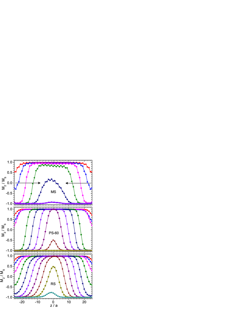
It is well established that magnetization reversal in FM nanowires proceeds by propagation and annihilation of a pair of domain walls that nucleate at the two free ends of the nanowire Fert and Piraux (1999); Hinzke and Nowak (2000); Thiaville et al. (2002). The coupling to an AF shell modifies the reversal mechanism, as previous experimentalMaurer et al. (2009) and numerical works have demonstratedMaurer et al. (2009); Patsopoulos and Kechrakos (2017). In FM/AF nanowires with a monocrystalline shell, the unsatisfied bonds at the interface act as nucleation centers of a secondary magnetization reversal mechanism, which in synergy to the domain wall propagation accelerate the reversal of the core magnetizationPatsopoulos and Kechrakos (2017). This behavior is seen in Fig. 6a as a lowering of the core magnetization in the central region between the two domain walls. As one can readily observe in Fig. 6, this secondary mechanism is absent in the PS and the RS nanowires, where reversal proceeds by clear domain wall propagation. The reason for disappearance of the secondary mechanism is the effective magnetic softening of the shell magnetization in the PS and RS nanowires, which no longer acts as a collection of nucleation centers for magnetization reversal. The magnetic softening of the shell interface magnetization results in lower domain wall velocities in the core, as seen in Fig. 7 and also by comparison of domain wall mobility values for the MS, PS and RS nanowires in Table 1.
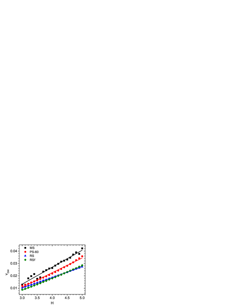
The contribution of the shell-interface magnetization in the modification of the wall velocities and mobility can be also deduced from Fig.7. The RSf nanowire that has higher value than the MS nanowire (see Fig. 4), exhibits a lower mobiltity. On a microscopic level, this trend is explained as the number of satisfied interface bonds is substantially higher for the RSf nanowire. These bonds being in their lowest energy state oppose their reversal under the applied field, acting as soft pinning centers for domain wall propagation.
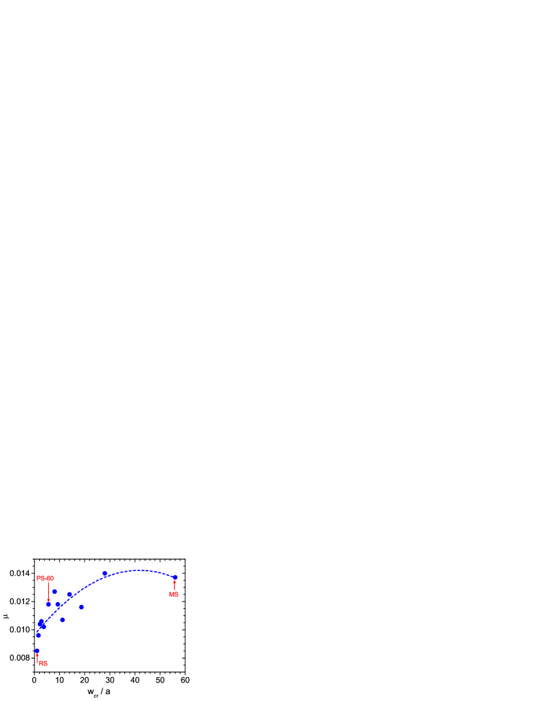
Thus, drag of the AF interface moments and increased magnitude due to polycrystallinity are the two factors acting in synergy to suppress the domain wall mobility in polycrystalline samples. A systematic decrease of wall mobility with decreasing grain size is shown in Fig. 8.
III.3 Angular dependence of and
In the present section, we study the changes introduced in the hysteresis behavior of core-shell nanowires, when the cooling field and the reversing field both lie at an angle with respect to the nanowire axis. In Fig. 9 we show the angular dependence of the hysteresis loop for samples with monocrystalline and polycrystalline shells.
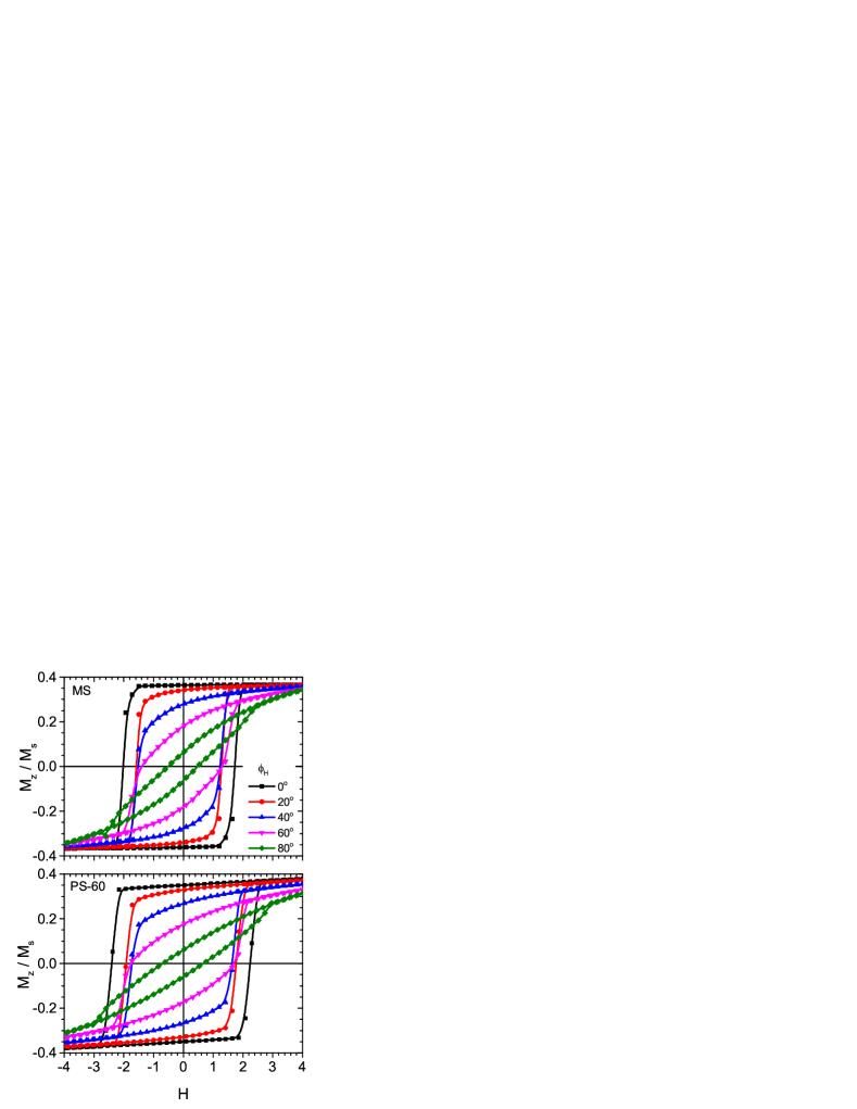
As the field angle relative to the nanowire axis increases, a gradual shrinking and tilting of the loop is observed, as both the crystallographic and shape anisotropies lie along the nanowire axis. Shell granularity does not change this trend. Analysis of the hysteresis loops at different field angles provides the angular dependence of the coercivity and EB shown in Fig. 10. A monotonous decrease of with field angle is seen for monocrystalline and granular samples. However, the polycrystalline and random samples exhibit higher coercivity values than the monocrystalline sample at all angles. This behavior is due to AF drag effect, discussed previously (see Fig. 4).
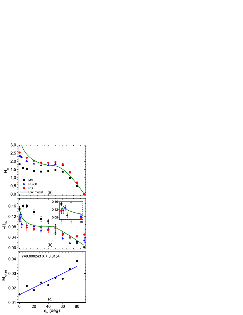
A more complex behavior is seen in Fig. 10b in the angular dependence of . In particular, the monocrystalline nanowire exhibits a weak increase of at small angles with a broad peak around . This peak is attributed to the competition between two distinct factors, namely, the susceptibility of the AF shell and the projection of the bias field on the applied field direction. First, we mention that the AF shell of the MS nanowire is a hard antiferromagnet with anisotropy along the z-axis. So, the susceptibility of the shell increases when the field angle changes from the parallel to the normal direction and consequently, the shell interface magnetization () increases too when the cooling field rotates with respect to the z-axis. Indeed, a linear fit , is seen in Fig. 10c. Second, for fixed shell interface magnetization, the bias field decreases as according to the Meiklejohn-Bean description of the EB effectNogués and Schuller (1999). Thus, an overall dependence is expected for the MS nanowire, which is characterized by an optimum field angle for maximum values. The optimum angle is within our model for the MS nanowire. When shell granularity is present, as in PS and RS nanowires, the shell becomes magnetically softer and the values drop. Furthermore, due to the random distribution of the easy axes of the shell grains, the susceptibility of the AF shell becomes isotropic and the broad peak of at vanishes. However, a sharp but weak increase of is seen for the polycrystalline sample for slightly off-axis directions. This behavior, despite being weak within our model is well understood within an effective SW model to be discussed next.
III.4 Effective Stoner Wohlfarth model
In this section, we fit our simulation results to an effective SW model. We define the SW model in dimensionless units, as follows:
| (2) |
where is the anisotropy of the FM assumed along the z-axis, is the applied field at an angle , the bias field at an angle and is an effective anisotropy that accounts for the coercivity enhancement due to drag of the AF interface momentsJiménez et al. (2009). We obtain the values of the dimensionless parameters in Eq. 2 from the simulation results (Fig. 10), as followsJiménez et al. (2009): and , where the superscript denotes values related to our Monte Carlo simulations. The anisotropy is not fitted to the coercivity valueJiménez et al. (2009), but is treated as an adjustable parameter. This is because the coherent rotation mechanism, inherent to the SW model, overestimates the coercivity for an applied field along the easy axis. The angle is also treated as an adjustable parameter. We perform numerical minimization of Eq. 2, leading for each value to one (reversible part) or two (irreversible part) extreme points that correspond to the equilibrium magnetization value(s). In Fig. 10a,b we compare the results of the SW model for the angular dependence of and with the Monte Carlo data.
We find that the Monte Carlo simulation data for the angular dependence of and can be satisfactorily described by a SW model with an effective off-axis unidirectional anisotropy making an angle with the nanowire axis. As previously, reported in the case of FM/Af bilayers, an effective off-axis anisotropy arises from the frustration of the AF interface moments due to interface roughness Jiménez et al. (2009). In the case of core-shell nanowires studied here, the source of magnetic frustration is the anisotropy disorder occurring at the core-shell interface due to shell granularity.
As a final remark, we discuss briefly recent experiments on electrodeposited Co/CoO nanowiresGandha et al. (2017), which showed giant exchange bias and an effective off-axis unidirectional anisotropy at a large angle () leading to an increase of the bias field by when the cooling field is applied at relative to the wire axis. Our simulations for Co/CoO nanowires, reproduce a similar trend, namely the appearance of an off-axis () anisotropy and a weak increase of the bias field () for a field applied at relative to the nanowire axis. Most importantly, the simulations point to the shell polycrystallinity as a source of generating effective off-axis anisotropy and optimum field directions for maximizing the EB effect in magnetic core-shell nanowires. However, the quantitative discrepancy between our simulations results and the experimental findingsGandha et al. (2017) we believe that is caused by the relative stronger bias effect in these samples, which most probably stems from atomic scale details of the interface structure leading to strong uncompensation, as for example, crystallographic orientation, interface roughness, alloying, etc, which are not considered in the present model.
IV Summary
We have studied the isothermal magnetic hysteresis of cylindrical Co/CoO nanowires with core-shell morphology using a classical spin model and Monte Carlo simulations. We have demonstrated that polycrystallinity of the CoO shell causes enhancement of coercivity and suppression of exchange-bias field relative to the monocrystalline shell. This behavior is mainly attributed to enhanced drag of the AF interface spins during reversal of the core spins. The same mechanism is responsible for reduction of domain wall mobility. Additionally, Co/CoO nanowires with monocrystalline shell, exhibit a weak () increase of their bias field when the reversing field is applied at a small angle () relative to the nanowire axis. On the other hand, shell granularity introduces an effective off-axis () unidirectional anisotropy due to frustration of the shell interface spins, leading to weak increase () of the bias field in an off-axis direction. Our results are in qualitative agreement with recent experimental observations in Co/CoO nanowiresGandha et al. (2017), and point to shell polycrystallinity as a source of generating off-axis unidirectional anisotropy in FM core - AF shell nanowires and exchange bias enhancement in off-axis directions.
Acknowledgments
DK acknowledges the hospitality in the Physics Department (University of Athens) during the course of this work and the financial support for dissemination of the work by the School of Pedagogical and Technological Education through project Strengthening of Research in ASPETE.
References
References
- Skomski (2003) R. Skomski, J. Phys. : Condens. Matter 15, R841 (2003).
- Fert and Piraux (1999) R. Fert and L. Piraux, J. Magn. Magn. Mater. 200, 338 (1999).
- Sellmeyer et al. (2001) D. J. Sellmeyer, M. Zheng, and R. Skomski, J. Phys. : Condens. Matter 13, R433 (2001).
- Bauer et al. (2004) L. A. Bauer, N. S. Birenbaum, and G. J. Meyer, J. Mater. Chem. 14, 517 (2004).
- Tartaj (2006) P. Tartaj, Curr.Nanosciece 2, 43 (2006).
- Parkin et al. (2008) S. S. S. Parkin, M. Hayashi, and L. Thomas, Science 320, 190 (2008).
- Thiaville and Nakatani (2006) A. Thiaville and Y. Nakatani, Topics Appl. Physics 101, 161 (2006).
- Bran et al. (2015) C. Bran, E. M. Palmero, Z. A. Liz, R. P. del Real, M. Spasova, M. Farle, and M. Vázquez, J. Phys. D: Appl. Phys. 48, 145304 (2015).
- Berganza et al. (2017) E. Berganza, M. Jaafar, C. Bran, J. A. Fernández-Roldán, O. Chubykalo-Fesenko, M. Vázquez, and A. Asenjo, Sci. Rep. 7, 11576 (2017).
- Palmero et al. (2015) E. Palmero, C. Bran, R. P. del Real, and M. Vázquez, Nanotechnology 26, 461001 (2015).
- Meiklejohn and Bean (1956) W. H. Meiklejohn and C. P. Bean, Phys. Rev. 102, 1413 (1956).
- Meiklejohn and Bean (1957) W. H. Meiklejohn and C. P. Bean, Phys. Rev. 105, 904 (1957).
- Nogués et al. (2005) J. Nogués, J. Sort, V. Langlais, V. Skumryev, S. Suriach, J. S. Muoz, and M. D. Bar, Phys. Rep. 422, 65 (2005).
- Iglesias et al. (2008) O. Iglesias, A. Labarta, and X. Batle, J. Nanosci. Nanotechnol. 8, 2761 (2008).
- Kools (1996) J. C. S. Kools, IEEE Trans. Magn. 32, 3165 (1996).
- Maurer et al. (2009) T. Maurer, F. Zighem, F. Ott, G. Chaboussant, and G. André, Phys. Rev. B 80, 064427 (2009).
- Tripathy et al. (2010) D. Tripathy, A. O. Adeyeye, K. Chakrabarti, and N. Singh, J. Appl. Phys. 107, 09D705 (2010).
- Gandha et al. (2017) K. Gandha, R. P. Chaudhary, J. Mohapatra, A. R. Koymen, and J. P. Liu, Physics Letters A 381, 2092 (2017).
- Buchter et al. (2015) A. Buchter, R. Wölbing, M. Wyss, O. F. Kieler, T. Weimann, J. Kohlmann, A. B. Zorin, D. Rüffer, F. Matteini, G. Tütüncüoglu, et al., Phys. Rev. B 92, 214432 (2015).
- Proenca et al. (2013) M. P. Proenca, J. Ventura, C. T. Sousa, M. Vazquez, and J. P. Araujo, Phys. Rev. B 87, 134404 (2013).
- Patsopoulos and Kechrakos (2017) A. Patsopoulos and D. Kechrakos, Nanotechnology 28, 285701 (2017).
- Chang et al. (2017) C.-. H.-. T. Chang, S.-C. Chen, J.-S. Tsay, and Y.-D. Yao, Appl. Surf. Science 405, 316 (2017).
- Newman and Barkema (1999) M. E. J. Newman and G. T. Barkema, Monte Carlo Methods in Statistical Physics (Oxford University Press, 1999).
- Dimitriadis et al. (2015) V. Dimitriadis, D. Kechrakos, O. Chubykalo-Fesenko, and V. Tsiantos, Phys. Rev. B 92, 064420 (2015).
- Nogués and Schuller (1999) J. Nogués and I. K. Schuller, J. Magn. Magn. Mater. 192, 203 (1999).
- Herzer (1990) G. Herzer, IEEE Trans. Magn. 26, 1397 (1990).
- Hinzke and Nowak (2000) D. Hinzke and U. Nowak, J. Magn. Magn. Mater. 221, 365 (2000).
- Thiaville et al. (2002) A. Thiaville, J. Garcia, and J. Miltat, J. Magn. Magn. Mater. 242-245, 1061 (2002).
- Jiménez et al. (2009) E. Jiménez, J. Camarero, J. Sort, J. Nogués, N. Mikuszeit, J. García-Martín, A. Hoffmann, B. Dieny, and R. Miranda, Phys. Rev. B 80, 014415 (2009).