Controlling steady-state second harmonic signal via linear and nonlinear Fano resonances
Abstract
Nonlinear signal even from a single molecule becomes visible at hot spots of plasmonic nanoparticles. In these structures, Fano resonances can control the nonlinear response in two ways. (i) A linear Fano resonance can enhance the hot spot field, resulting enhanced nonlinear signal. (ii) A nonlinear Fano resonance can enhance the nonlinear signal without enhancing the hot spot. In this study, we compare the enhancement of second harmonic signal at the steady-state obtained via these two methods. Since we are interested in the steady-state signal, we adapt a linear enhancement which works at the steady-state. This is different than the dark-hot resonances that appears in the transparency window due to enhanced plasmon lifetime.
1 Introduction
Metal nanoparticles (MNPs) trap incident radiation into nm-size hot spots as localized surface plasmon (LSP) oscillations. Intensity of the hot spot (near field) can be times of the one for the incident field (1, 2) or even further (3). This phenomenon enables several technical applications based on the enhancement of linear and nonlinear responses. For instance, a fluorescent molecule in the vicinity of the hot spot becomes detectable (4, 5), which would not be possible with a weak intensity incident field. Localization also strengthens the nonlinear properties of molecules positioned in the vicinity of the hot spots. Signal from a Raman-reporter molecule can be enhanced remarkably (6). Such a great increase in the signal results from the localization of both the incident and the produced (Raman) fields (7). In this way, surface enhanced Raman scattering (SERS) enables detection of Raman signal even from a single molecule. Similarly, nonlinear processes like second harmonic generation (SHG) (8, 9) and four wave-mixing (FWM) (10, 11) are also enhanced.
Enhanced hot spot field also enables the observation of Fano resonances (12, 13), analog of electromagnetically induced transparency (EIT) (14). In EIT, excited level is hybridized by coupling to a third one via a strong microwave field. Hybridization is weak such that the splitting in the excited state remains in the spectral width of the excited state. The two paths operate out of phase, one emits while the other one absorbs, and a transparency window appears. A transparency window, Fano resonance (FR), also appears in the plasmon response, when a quantum emitter (QE) is placed in the hot spot of MNP (1). In a FR, the weak hybridization is induced by the interaction of the QE with the own polarization of the plasmon near field. A FR can appear when the plasmon mode of MNP is coupled to a longer lifetime excitation. For instance, it was shown that FR can appear in all-plasmonic system when the excited LSP is coupled to a long living dark plasmon mode (15, 16).
FRs can control linear and nonlinear properties of MNPs (17, 18, 19, 20, 21). Typical lifetime of LSP oscillations is extremely short, i.e. seconds. A FR can increase the lifetime of plasmon excitation (22, 23, 24, 25). In the same incident field strength, a MNP with a FR can accumulate more intense field at the hot spot. These are called as dark-hot resonances (26). This enhancement in the plasmon lifetime enables the operation of spasers (27, 28), nano-lasers. Dark-hot resonances appear strongest when the incident field is resonant to the transparency window (26). Even though excitation reaches the transparency (zero) in the steady state, hot spot becomes more intense for some time due to enhanced plasmon lifetime. Dark-hot resonances are cleverly adapted in enhancing the SERS (29, 30, 31) and FWM (32) signals further. For instance, a double resonance system, where exciting and converted frequencies are tuned to two plasmon resonances (33), can yield a stronger SERS signal. Besides that, when exciting and converted frequencies are aligned with two FRs, then the signal can be enhanced several orders on the top of the double resonance scheme. One can conduct similar results also for SHG process.
In this manuscript, we study the control of steady-state of second harmonic signal via path interferences (i) in the linear and (ii) nonlinear responses. For enhancing the linear response (i), so the nonlinear one, we use path interference scheme different than the dark-hot resonances. The scheme we use, a novel scheme to our best knowledge, enhances the hot spot field intensity in the steady-state, which also leads to enhancement in the second harmonic field intensity. Next, we use a path interference scheme (6) which enhances only (ii) the nonlinear response without increasing the hot spot field intensity. This method can be useful when MNP-QE hybrid system is excited with a strong pulsed laser. For instance, experiments using a molecule type with very weak SHG response would necessitate a strong laser. This may heat the molecule too much in the presence of a dark-hot resonance or enhancement via method (i) we introduced here. In such a case, enhancing the second harmonic signal without increasing the hot spot field intensity could be very useful.
It is demonstrated that all plasmonic FRs can silence SHG. Here, we show that such a silencing (suppression) is also possible in the presence of a molecule resonant to the second harmonic signal. We use a Lorentzian dielectric function for molecule and demonstrate the suppression with the exact solution of 3D Maxwell equations. This was predicted by an analytical method (9) previously but not confirmed with 3D solutions.
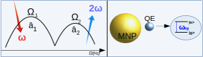
The manuscript is organised as follows. In Sec.2, we describe the mechanism for the SHG processes in plasmonic nano-materials. We derive effective Hamiltonian for a second harmonic converter MNP coupled with a QE. We derive the equations of motion for the plasmon modes and the QE. In Sec.3, we discuss two different enhancement schemes. In Sec.3.1, we choose the level spacing () of the QE such that it is coupled to the driven plasmon mode, in Figure 1. This enhances the steady-state intensity of the hot spot, so the second harmonic signal which is proportional to the square of the hot spot field. In Sec.3.2, we couple the QE to the mode in which second harmonic oscillations take place. This enhances the second harmonic signal without altering the hot spot field intensity of the driven mode. Sec.4 contains our conclusions.
2 Dynamics of the system
In this section, we derive the effective Hamiltonian for a plasmonic second harmonic converter coupled to a QE. Hamiltonian contains two possibilities; QE coupled to (i) driven mode and to the (ii) high energy plasmon mode into which second harmonic oscillations take place. We derive the equations of motion for each case. These equations are the basis on which we discuss how one can gain control over the nonlinear signal with and without modifying linear response.
2.1 Hamiltonian
SHG (frequency doubling) process in a plasmonic nano-material can be described as follows. When plasmonic structure is illuminated with a strong incident laser field () of frequency , the plasmon oscillations are excited in the mode. Combination of the two plasmon in the mode yield to create a single plasmon in the mode (35) oscillating as . Second harmonic conversion process takes place between plasmons (34, 18, 36) since the overlap integral, Eq.1 being, attains a large value. The Hamiltonian of this process can be written as
| (1) |
The integral in the parenthesis, , is the overlap integral. It (i) determines the strength of the SHG process, (ii) demonstrates us why second harmonic conversion takes place between plasmon of different frequencies and (iii) gives the selection rules for SHG process. Why SHG is not observed in the far-field for a centro-symmetric plasmonic nano-structure can be observed from this overlap integral (37). When a QE couples to one of the hot spots of the MNP, it strongly interacts with that mode. Small decay rate of QE creates a weak hybridization, in which two or more absorption/emission paths come into play. Depending on the level spacing () of the QE, it is possible to introduce different interference schemes.
The Hamiltonian of the system can be written as the sum of the energy of the plasmon oscillations (), quantum emitter () and the energy transferred by the pump source ()
| (2) | |||||
| (3) |
as well as the SHG process as defined in Eq.(1) and the interaction of the QE with the plasmon-polariton modes .
| (4) | |||||
| (5) |
Here the parameters and , in units of frequency, are the coupling strengths of the linear and second harmonic responses of the MNP to the QE respectively. is the overlap integral defined in Eq.(1) and () is the ground (excited) state of the QE.
2.2 Equations of motion
The equations of the motion of the system can be derived by using Heisenberg equations (e.g. ). In this work, we are not interested in the quantum optical features of the modes. We replace the operators and with complex numbers and (38) respectively and equations of the motion for the plasmon amplitudes and density matrix elements, respectively, can be obtained as
| (6a) | ||||
| (6b) | ||||
| (6c) | ||||
| (6d) | ||||
where and are the damping rates of plasmon modes and quantum emitter, respectively. The conservation of probability and population inversion with the off-diagonal decay rate of the QE accompanies Eqs.(6a-6d).
In the steady state, the two plasmon mode amplitudes and the diagonal density matrix elements can be written as
| (7) |
The off-diagonal density matrix element determines the electric polarization of the QE. Its steady-state oscillations take the form and when QE is coupled to mode and mode respectively. Although, we present our results with the numerical time evolutions of Eqs.(6a-6d) in Figure 2 and Figure 3, we study the steady-state carefully in order to gain understanding over different interference schemes.
3 Enhancement and suppression
In this section, we examine the second harmonic response of the plasmonic nanostructure coupled to a QE. The relative enhancement factor (EF) for each mode is defined in the presence and absence of a QE as
| (8) |
We aim to control the amplitudes of both linear and nonlinear fields. In order to do that, we use a basic model and obtain the steady-state amplitudes for the generated second harmonic plasmons. From a single equation we demonstrate the origin of enhancement and suppression. We compare two different cases for the level spacing of the QE close to the (i) linear and (ii) second harmonic frequency oscillations. We show that in either case enhancement and suppression of the SHG process is possible. In the first case both enhancement and suppression in the second harmonic field is proportional to square of the linear field. In the latter case, however, the enhancement can be obtained silently i.e without modifying hot spot field intensity of mode. Then, we compare the predictions of our model in suppression phenomena with 3-dimensional FDTD simulations. We confirm that suppression of the SHG process is observed in the predicted spectral position.
3.1 Coupling quantum emitter to mode
Illumination of MNPs with an electromagnetic field of frequency results in strong field enhancement in the vicinity of the MNPs. By placing QE into these regions, further enhancement in the hot spot field intensities, due to linear Fano resonances, can be obtained. In this part, we show that hot spot field intensity can be enhanced not only in the initial times, but also in the steady-state when a QE is coupled to driven mode of the MNP. We also demonstrate the cosequences of this process in the nonlinear response.
The enhancement and suppression of the second harmonic field intensity is possible by enhancing the linear response. When a QE is couple to mode, path interference effects take place for the linear field intensity. Since we are examining the coupling of QE to the driven mode, interaction strength between QE and second harmonic response can be neglected (e.g. ). The source term for off-diagonal density matrix element, however, can be considered as mode. Inserting and Eq.(7) into Eqs.(6a-6d), one can find steady state solution for and modes as
| (9) | |||||
| (10) |
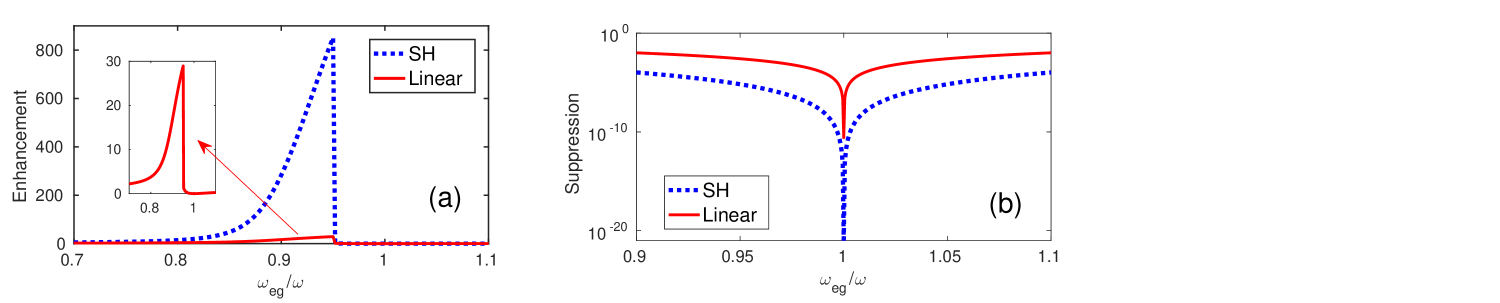
The enhancement of intensity can be obtained by minimizing the denominator of the Eq.(9). When oscillation frequency of the linear response, , is off-resonant with , the residual part of the first term can be eliminated by choosing appropriately level spaced () QE and/or tuning interaction strength () by adjusting separation between MNP and QE. That is, for the choice of the level spacing, , which cancels imaginary part of the first term, the hot spot field intensity can be enhanced about 30 times. Due to quadratic dependece on in Eq.(10), the enhancement in the second harmonic is approximately square of the linear mode, see Figure 2a.
When and is significant, the second term in the denominator of the Eq.(9) becomes . When we scale all the frequencies by the optical drive, , becomes very large. In this case, the second term dominates the denominator and results a very small which yields the observed transparency for linear field and hence for the nonlinear field. This is depicted in Figure 2b.
3.2 Coupling quantum emitter to mode
SHG processes can be enhanced and suppressed by constructive and destructive interferences of the frequency conversion paths. If the level spacing of QE is chosen closely to second harmonic frequency its interaction with the mode becomes stronger compared to mode as it is highly off-resonant from driven mode. In addition, the hot spots of each mode can emerge at different spatial positions. By placing QE at the hot spot of mode, coupling of QE to the driven mode becomes negligible (i.e. ). One can observe that steady-state solution for the QE is in the form with is a constant in time. Inserting this form into Eq.(6c) and using Eq.(7), the steady state amplitude for the plasmons in the mode can be obtained from Eqs.(6a-6d) as
| (11) |
Interpretation of why enhancement and suppression take place in second harmonic field can be done by examining the denominator of the Eq.(11). Here, we demonstrate how second harmonic field can be enhanced without any modification in the linear response, .
Similar to previous part, the enhancement of intensity can be obtained by minimizing the denominator of the Eq.(11). That is, for the choice of the level spacing, , which cancels imaginary part of the first term, second harmonic field intensity can be enhanced about 1500 times without changing linear hot spot field intensity, see Figure 3a. The enhancement factor in Figure 3a is obtained for the choice of and the interaction strength . For a high quality plasmonic nanostructure (39), this factor can be even larger.
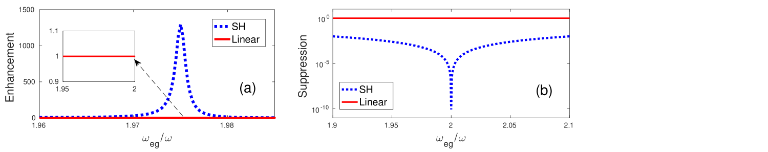
The denominator of the Eq.(11) also demonstrates us the possibility of a SHG suppression effect. We examine the denominator of the last term in the denominator of the Eq.(11). When a QE level spacing is chosen close to the second harmonic frequency , the last term becomes . Typical values for the decay rates of QEs are very small compared to all other frequencies. For example for quantum dots (40). With a coupling constant of sufficient strength, term dominates the denominator of the Eq.(11) and suppression of the second harmonic field emerges, see Figure 3b. Here, again we do not observe any change in the linear field intensity.
We underline that the results presented in Figure 2 and Figure 3 are the exact solutions of Eqs.(6a-6d) without any approximation.
We note an important point. For the system parameters we treat as a sample system, (i) enhancement of the linear response, i.e. , appears rather small, about 30 times. When we compare this with the (ii) nonlinear Fano resonance method, SHG enhancement from (ii) appears larger. However, this observation can change dramatically for using a sample system with different parameters. Enhancement via linear Fano resonances, in general, can be expected to be much larger than the nonlinear Fano resonances. Because SHG enhancement with linear Fano resonance is the square of the linear response, which can be more than two orders of magnitude in other systems.
3.3 Comparision of the suppression in 3D simulations
Suppression of the SHG with all-plasmonic Fano resonances was shown in Ref. (19). In a previous study (9), we anticipated the presence of the suppression effect also for a Fano resonance originating from a QE. The method we have used in this work (9) was a first order approximation for SHG. Here, we use self consistent Maxwell equations also for the SHG process and demonstrate the presence of the anticipated suppression effect with 3D-FDTD simulations.
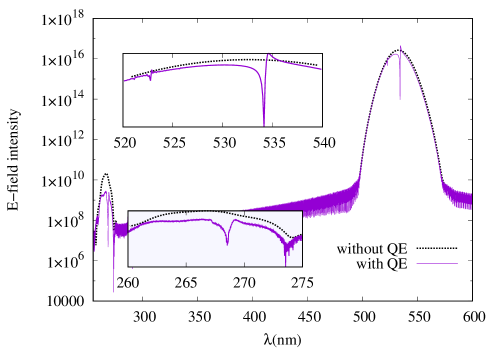
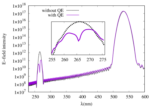
In Figure 4, we compare the predictions of our model for suppression effect with the 3D FDTD simulation in which Maxwells equations can be solved using conventional Yee cell algorithm (41). We use nanospheres for MNP and QE as in Figure 1. Radii of the gold nanoparticle and QE are 35 nm and 15 nm respectively. We use experimental data for the dielectric function of the gold nanoparticle (42) with nonlinearity. We place an auxilary QE in the vicinity of the MNP, which has a Lorentzian dielectric function. The Lorentzian peak is centred around 530 nm for Figure 4a and 265 nm for Figure 4b. Excitation wavelength is 530 nm with 30 THz bandwidth and amplitude of the source beam is set V/m to have a strong nonlinear response. In Figure 4a driven mode of MNP strongly interacts with QE having a sharp resonance at 530 nm, suppression emerges in both modes, see insets of Figure 4a. When a gold-MNP strongly interacts with QE having a sharp resonance at 265 nm, the suppression in the second harmonic response emerges without significant change in the linear response, see Figure 4b. We wanted to be confident about the origin of the dip at 265 nm in Figure 4. In order to remove the possibility that dip originates from the absorption induced by QE, we illuminated the sample by a pulse centered at 265 nm and checked if a linear resonance appears. Since we observed that Fano resonance, we became confident that dip does not originate from absorption.
4 Conclusions
We demonstrate that one can gain control over the steady-state second harmonic signal from a plasmonic nano-material via two kinds of Fano resonances. In the first method, with linear Fano resonance, one can increase the hot spot field intensity for the driven field, . This also increases the second harmonic signal, . We develop a method for enhancing the steady state linear response of a MNP. This is different than the dark-hot resonances which appear at the transparency window due to plasmon lifetime enhancement. In the second method, with nonlinear Fano resonance, one can gain control over the second harmonic signal without altering the hot spot field intensity for the driven mode. Using the exact solutions of Maxwell equations, we also show that second harmonic signal is suppressed when the QE is tuned to , as predicted (9). This phenomenon has also been observed in all-plasmonic Fano resonances (19, 43).
Acknowledgments
MG and MET acknowledges support from TUBITAK Grant No. 117F118.
References
- (1) Wu, X., Gray, S.K. and Pelton, M., 2010. Quantum-dot-induced transparency in a nanoscale plasmonic resonator, Optics express, 18(23), pp.23633-23645.
- (2) Stockman, M.I., 2011. Nanoplasmonics: past, present, and glimpse into future, Optics express, 19(22), pp.22029-22106.
- (3) Hoppener, C., Lapin, Z.J., Bharadwaj, P. and Novotny, L., Self-similar gold-nanoparticle antennas for a cascaded enhancement of the optical field, Physical Review Letters, 109, 017402 (2012).
- (4) Yuan, H., Khatua S., Zijlstra, P., Yorulmaz M. and Orrit, M., Thousand-fold Enhancement of Single-Molecule Fluorescence Near a Single Gold Nanorod, Angewandte Chemie International Edition, 52, 1217-1221 (2013)
- (5) Anger, P., Bharadwaj P. and Novotny, L., Enhancement and quenching of single-molecule fluorescence, Physical Review Letters, 96, 113002 (2006)
- (6) Postaci, S., Yildiz, B.C., Bek, A. and Tasgin, M.E., 2017. Silent enhancement of SERS with unmodified hot spots, arXiv preprint arXiv:1709.09230.
- (7) Ding S.Y., Yi J., Li J.F., Ren B.,Wu D.Y., Panneerselvam R., Tian Z.Q., Nanostructure based plasmon-enhanced Raman spectroscopy for surface analysis of materials, Nature Reviews Materials, 1, 16021 (2016)
- (8) Ren M.L., Liu S.Y., Wang B.L., Chen B.Q., Li J., Li Z.Y., Giant enhancement of second harmonic generation by engineering double plasmonic resonances at nanoscale, Optics Express, 22, 28653-28661 (2014)
- (9) Turkpence D., Akguc G.B., Bek A.,Taşgın M.E., Engineering nonlinear response of nanomaterials using Fano resonances, Journal of Optics, 16, 105009 (2014)
- (10) Poutrina E., Ciraci C., Gauthier D.J., Smith D.R., Enhancing four-wave-mixing processes by nanowire arrays coupled to a gold, Optics Express, 20, 11005-11013 (2012)
- (11) Singh S.K., Abak M.K., Taşgın M.E., Enhancement of four-wave mixing via interference of multiple plasmonic conversion paths, Physical Review B93, 035410 (2016).
- (12) Lukyanchuk, B., Zheludev, N.I., Maier, S.A., Halas, N.J., Nordlander, P., Giessen, H. and Chong, C.T., 2010. The Fano resonance in plasmonic nanostructures and metamaterials, Nature materials, 9(9), p.707.
- (13) Verellen, N., Sonnefraud, Y., Sobhani, H., Hao, F., Moshchalkov, V.V., Dorpe, P.V., Nordlander, P. and Maier, S.A., 2009. Fano resonances in individual coherent plasmonic nanocavities, Nano letters, 9(4), pp.1663-1667.
- (14) Scully, M.O. and Zubairy, M.S., Quantum optics., Cambridge university press (1997).
- (15) Tassin P., Zhang L., Koschny T.H., Economou E.N., Soukoulis C.M., Low-loss metamaterials based on classical electromagnetically induced transparency, Physical Review Letters, 102, 053901 (2009)
- (16) Liu N., Langguth L., Weiss T., Kastel J., Fleischhauer M., Pfau T., Giessen H., Plasmonic analogue of electromagnetically induced transparency at the Drude damping limit, Nature Materials,8 758–762 (2009)
- (17) Butet J., Bachelier G.,Russier-Antoine I., Bertorelle F., Mosset A., Lascoux N., Jonin C., Benichou E., and Brevet P.F., Nonlinear fano profiles in the optical second-harmonic generation from silver nanoparticles, Physical Review B 86, 075430 (2012).
- (18) Thyagarajan K., Butet J., and Martin O.J.F., Augmenting second harmonic generation using fano resonances in plasmonic systems, Nano letters 13, 1847-1851 (2013).
- (19) Berthelot J., Bachelier G., Mingxia Song, Padmnabh Rai, Gérard Colas Des Francs, Alain Dereux, and Alexandre Bouhelier, Silencing and enhancement of second-harmonic generation in optical gap antennas, Optics express 20, 10498-10508 (2012)
- (20) Walsh, G.F. and Negro, L.D., Enhanced second harmonic generation by photonic–plasmonic fano-type coupling in nanoplasmonic arrays, Nano letters 13, 3111-3117 (2013).
- (21) Paspalakis, E., Evangelou, S., Kosionis, S.G. and Terzis, A.F., Strongly modified four-wave mixing in a coupled semiconductor quantum dot-metal nanoparticle system, Journal of Applied Physics 115, 083106 (2014).
- (22) Sadeghi, S.M., Wing, W.J. and Gutha, R.R., Undamped ultrafast pulsation of plasmonic fields via coherent exciton-plasmon coupling, Nanotechnology, 26 (8),(2015).
- (23) ElKabbash M., Rashed A.R., Kucukoz B., Nguyen Q., Karatay A., Yaglioglu G., Ozbay E., Caglayan H., Strangi G., Ultrafast transient optical loss dynamics in exciton-plasmon nano-assemblies, Nanoscale, 9, 6558-6566 (2017).
- (24) Tasgin M.E., Metal nanoparticle plasmons operating within a quantum lifetime, Nanoscale 5 18 (2013):8616-8624
- (25) Yıldız Karakul, B.C., Enhancement of plasmonic nonlinear conversion and polarization lifetime via fano resonances, Middle East Technical University, (2017)
- (26) Stockman, M.I., Nanoscience: Dark-hot resonances, Nature 467, 541-542 (2010).
- (27) Stockman, M.I., The spaser as a nanoscale quantum generator and ultrafast amplifier, Journal of Optics 12, 024004 (2010).
- (28) Noginov, M.A., Zhu, G., Belgrave, A.M., Bakker, R., Shalaev, V.M., Narimanov, E.E., Stout, S., Herz, E., Suteewong, T. and Wiesner, U., Demonstration of a spaser-based nanolaser. Nature, 460 7259 (2009).
- (29) He J., Fan C., Ding P., Zhu S., Liang E., Near field engineering of Fano resonances in a plasmonic assembly for maximizing CARS enhancements, Scientific Reports, 6, 20777 (2016)
- (30) Ye J., Wen F., Sobhani H., Lassiter J.B., Van Dorpe P., Nordlander P., Halas N.J., Plasmonic nanoclusters: near field properties of the Fano resonance interrogated with SERS, Nano Letters, 12, 1660-1667 (2012)
- (31) Zhang Y., Zhen Y.R., Neumann O., Day J.K., Nordlander P., Halas N.J., Coherent anti-Stokes Raman scattering with single-molecule sensitivity using a plasmonic Fano resonance, Nature Communications, 5, 4424 (2014)
- (32) Zhang Y., Wen F., Zhen Y.R., Nordlander P., Halas N.J., Coherent Fano resonances in a plasmonic nanocluster enhance optical four-wave mixing, Proceedings of the National Academy of Sciences, 110, 9215-9219 (2013)
- (33) Chu Y., Banaee M.G., Crozier K.B., Double-resonance plasmon substrates for surface enhanced Raman scattering with enhancement at excitation and stokes frequencies, ACS Nano, 4, 2804-2810 (2010)
- (34) Grosse N.B., Heckmann J., Woggon U., Nonlinear plasmon-photon interaction resolved by k-space spectroscopy, Physical Review Letters, 108, 136802 (2012)
- (35) M. Finazzi and F. Ciccacci , Plasmon-photon interaction in metal nanoparticles: Second-quantization perturbative approach, Physical Review B86, 035428 (2012)
- (36) Wunderlich, S. and Peschel, U., Plasmonic enhancement of second harmonic generation on metal coated nanoparticles, Optics Express, 21(16),(2013).
- (37) Tasgin M.E., Salakhutdinov I., Kendziora D., Abak M.K., Turkpence D., Piantanida L., Fruk L., Lazzarino M., Bek A., Fluorescence excitation by enhanced plasmon upconversion under continuous wave illumination, Photonics and Nanostructures-Fundamentals and Applications, 21, 32–43 (2016)
- (38) Premaratne, Malin and Stockman, Mark I. Theory and technology of SPASERs, Advances in Optics and Photonics 9.1 (2017): 79-128.
- (39) Min B., Ostby E., Sorger V., Ulin-Avila E., Yang L., Zhang X., Vahala K.,High-Q surface-plasmon-polariton whispering-gallery microcavity, Nature, 457 (2009)
- (40) Kosionis, S.G., Terzis, A.F., Sadeghi, S.M. and Paspalakis, E., Optical response of a quantum dot-metal nanoparticle hybrid interacting with a weak probe field, Journal of Physics: Condensed Matter, 25 4 (2012).
- (41) Yee, K., 1966. Numerical solution of initial boundary value problems involving Maxwell’s equations in isotropic media, IEEE Transactions on antennas and propagation, 14(3), pp.302-307.
- (42) Johnson, P.B. and Christy, R.W , Optical Constants of Noble metals, Phys Rev B, 6, 4370, (1972)
- (43) Yıldız B.C., Taşgın M.E., Abak M.K., Coskun S., Unalan H.E., Bek A., Enhanced second harmonic generation from coupled asymmetric plasmonic metal nanostructures, Journal of Optics, 17, 125005 (2015).