Consolidating Multiple FemtoSecond Lasers in Coupled Curved Plasma Capillaries
Abstract
Consolidating multiple high-energy femtosecond scale lasers is expected to enable implementation of cutting edge research areas varying from wakefield particle accelerators to ultra-high intensity laser pulses for basic fresearch. The ability to guide while augmenting a short-pulse laser is crucial in future laser based TeV particle accelerators where the laser energy depletion is the major setback. We propose, analyze and experimentally demonstrate consolidating multiple femtosecond pulse lasers in coupled curved capillaries. We demonstrate a proof of principle scheme of coupled curved capillaries where two femtosecond laser pulses are combined. We found that the details of the coupling region and injection scheme are crucial to the pulse consolidations. Furthermore, our simulations show that high-intensity short pulse laser can be guided in a small curvature radius capillary. Incorporating these finding in a curved capillary laser coupler will be a significant step towards realization of meters long TeV laser based particle accelerators.
pacs:
52.38.-r,52.40.Db,41.75.JvHigh intesity short pulse lasers have opened new horizons in many research aspects of light-matter interactionLedingham and Galster (2010). Laser systems of up to several PW level were demonstrated and utilized in experiments. Research areas ranging from astrophysics-in-lab to TeV laser based particle accelerators are the main beneficiaries of the novel high intensity laser physics Borghesi (2014); Bulanov et al. (2015); Corde et al. (2013); Daido et al. (2012); Esarey et al. (2009). Nevertheless, generation of PW scale pusles from a single source turned out to be exceedingly complicated task that requires both specifically engineered expensive components as well as expertise, limiting the number of operating systems Danson et al. (2015). Medium scale energy lasers (100TW) have become the working tool in many university roomsize research labs. It is therefore expected that combining pulses from such systems can fill the gap and provide a much wider accessability to PW laser pulses. On a different aspect, guided laser pulse in a plasma channel that is created in a capillary was shown to accelerate electrons up to GeV energy levels Leemans et al. (2006); Kim et al. (2013); Leemans et al. (2014) utilizing laser wakefield acceleration scheme (LWFA). Comparing that to the kilometer-length conventional accelerators it is clear why the LWFA is considered to be a most promissing option for future high energy particle accelerators. The three main limitations of LWFA are laser beam diffraction, electron dephasing, and laser energy depletion Esarey et al. (2009). It has been demonstrated in the past by many groups that a hollow radial plasma density profile enables to extend the length along which the beam remains sufficiently focused to up to tens of centimeters Ehrlich et al. (1996); Zigler et al. (1996); Levin et al. (2006). Electron dephasing occurs when the electron bunch begins to slip ahead of the range in the wakefield where they are accelerated. We have also previously shown that tapering the plasma density along the direction of propagation can postpone electron dephasing Kaganovich et al. (1999, 2001). Energy depletion of the laser beam is commonly envisaged as being dealt with by concatenating several acceleration stages. Multi-staging is expected to avoid most of these problems, allowing to locally inject a different, undepleted laser pulse into the plasma channel which can be independently delayed to rephase the driver with the accelerating electrons. Multi-stage scheme has been recently proved Steinke et al. (2016) using plasma mirrors to inject the laser into preformed plasma channels and plasma lens to capture the laser generated electrons before sending them into the subsequent acceleration stages. This scheme sets a significant distances between the stages and has the drawback of a low coupling efficiency far below the suitable for future accelerators. A possibility of adding a second laser through a curved capillary was suggested several years ago Zigler (2016) and recently simulated Luo et al. (2018).
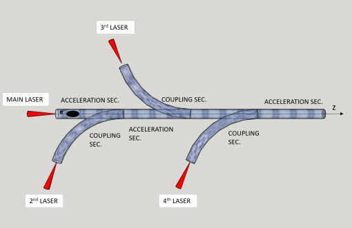
In this letter, we demonstrate a novel concept of concatenating consecutive acceleration stages. The proposed concept is based on a ”Fish-Bone” like structure (see Fig. 1 for a possible realization). The main laser accelerates an electron bunch by the LWFA scheme, till the laser energy depletion. Then, curved channels allow to add new properly timed laser pulses on the acceleration axis driving the wakes to further accelerate the bunch. With this scheme the overal length of a TeV accelerator can be reduced by at least an order of magnitude as the accelerator units are closely packed. Nevertheless, there are two major issues that must be addressed in order to implement this innovative scheme.
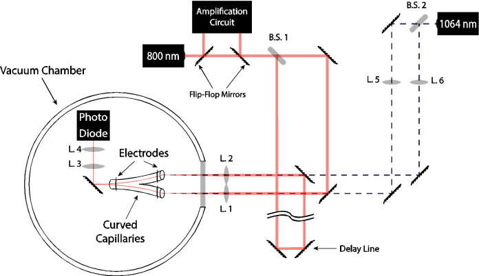
First, the coupling region of the two capillaries must be carefully designed so that the laser pulses will be properly joined while the electron bunch will not be broken. Secondly, the injecting cappilary should be curved to the smallest possible radius in order to shorten the injection area. Addressing the first and formost issue, we have conducted a proof of principle experiment by coupling two laser beams. The scheme implemented in this proof of principle is a ”Y” shaped plasma channel coupling region (see Fig. 2). Each branch comprises a curved capillary filled with a plasma of a radial density profile. The capillaries inner radii is 250m, and the radius of curvature is 100 cm. The capillaries Y-junction was manufactured by a 3D-printing system with spatial resolution of 12m Filippi and et al. (2018). The prining material was chosen to satisfy the experimental requirements of the system. In particular, the material was desinged to be hard in order to reduce over ablation and transparrent to facilitate light based diagnostics of the plasma channel. Accordingly, a based material were used.
The generation of the plasma channel is based on the laser trigger ablative technique Palchan et al. (2007). An alternative approach of gas driven capillaries is obviuosly possible as well. The electronic part of the discharge mechanism consists of a high-voltage source, a capacitor for storing the energy to be discharged and a resistor for limiting the charging current. The anode and cathode are two electrodes placed at either end of the capillary. The triggering is obtained by a 1064 nm laser of 10 ns pulses with 50 mJ per pulse. The triggering beam is splitted by a beam splitter to timely trigger each branch (simultaneously or with a predetermined time delay). Following the trigger, an avalanch ablative process is started and due to the discharge current a plasma is formed in the capillaries. For an electric discharge of 15 kV along the 5cm of the capillary, a plasma with an average density of cm-3 is formed with an approximately hollow RDP which is suitable for the laser guiding. This isn’t far from the optimal plasma density for LWFA of cm-3 which can be easily reached by reducing the capillary radius or increasing the current furnished by the circuit Kaganovich et al. (1999). The main beam to be guided, (red line in Fig. 2), originates from a 800 nm laser, which produces 5 nJ, 12.5 fs pulses, wihch can be amplified to a pulse of 5 mJ, 30 fs. This beam is split as well (B.S. 1) for the two capillaries, with one of the branches going through a delay line, after which they each reach a lens (L.1,2) and are focused into the capillaries. At the exit of the capillaries, an imaging system (L. 3,4) enables the intensity measurment of the transmitted light. The lifetime of the plasma channel (with its proper density parameters) is approximately 100ns. Accordingly the timing of the channel generation and the main laser pulse injection is a crucial parameter. Utilizing the laser triggering technique with a time jitter of about 20ns is essential to meet these strict timing requirement
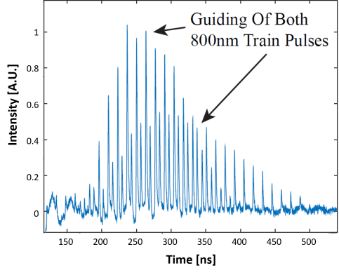
A clear experimental demonstration of consolidation of two laser pulses in the curved capillary Y junction is shown in Fig. 3. Two 800nm pulse trains are injected into the two separate entry points of the capillaries. Each pulse in the train contains 5nJ and is of 12.5fs duration. The pulse repetition rate is 76GHz and a 5ns time delay is introduced between the two branchews in order to distinguish one from the other. The output enerrgy is measured at the oputput of the combined capillary and is shown in the figure. It is clear that both pulses propagates through the junction with a considerable efficiency. Furthermore, the time duration of the guiding window which starts about 250ns after the trigger pulse, is clearly shown in Fig. 3.
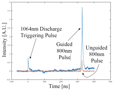
A demonstration of the guiding effect of a high power beam is given in Figure 4. The exit magnitude of the guided high intensity (0.1TW) pulse is 6 times stronger with the guiding effect compared to a non guiding conditions where the main pulse inefficiently drifts through the curved capillary by moltiple internal reflections.
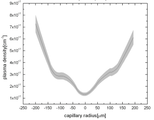
Having experimentally established the consolidation of two pulses in a curved capillary Y junction and the transmission of high intensity short pulse in a curved capillary we proceed to tackle the second issue, namely significantly reducing the curvature radius of each branch. Here we propose a numerical simulation study of possible parameters to reach the desired goal. The simulations are based on the TURBOWAVE code Gordon et al. (2000); Gordon (2007). Fig. 5 presents the measured plasma density in a capillary discharge. The inset shows the density profile used in the simulations.
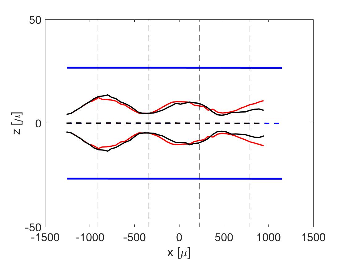
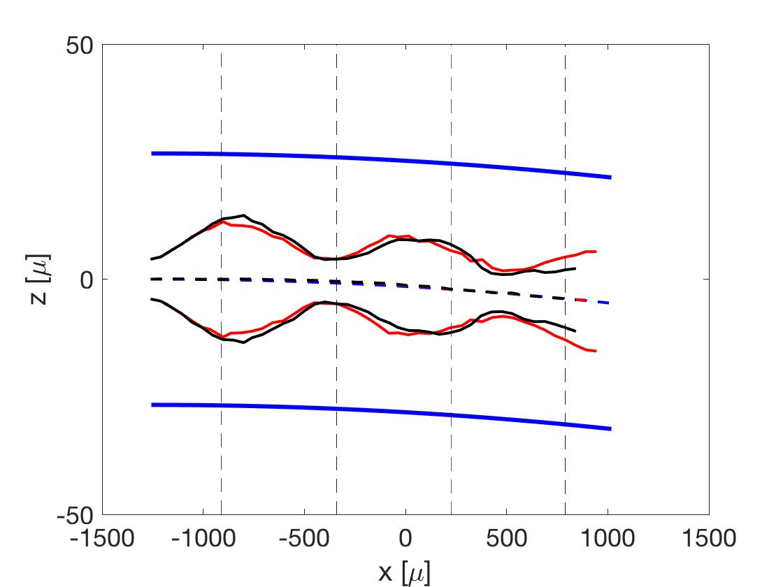
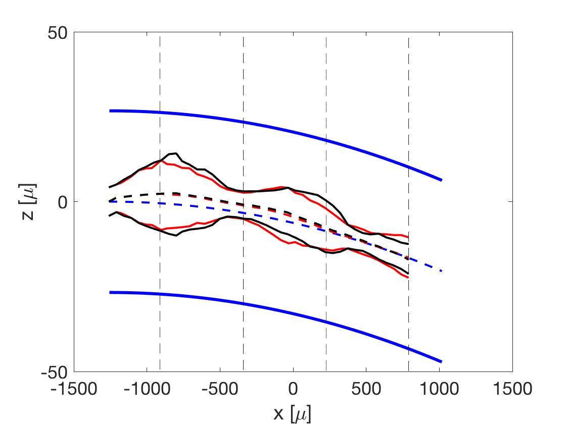
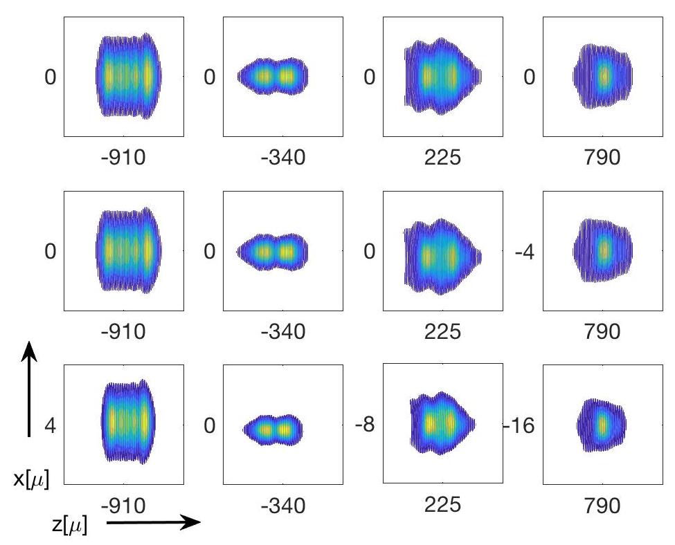
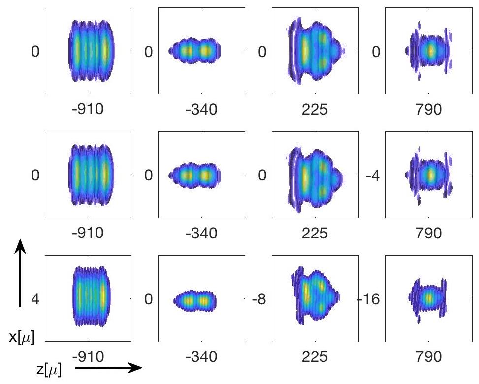
The envelope of a propagating high intensity short pulse lase in a plasma channel is shown in Fig. 6 for three values of curvature radius and two laser intensities. The left box in Fig. 6 is for a straight capillary, the middle for a curvature radius of 50cm and the right is for a 12.5cm curvature bent capillary. The axial length of the simulated capillary is 2.5mm. In all cases red line is for and black line for . The guiding of the pulse along the plasma channel is evident even for the 12.5cm curvature radius. Following the propagation of the laser pulse along the plasma channel we found that the tpulse changes its volume in both axial as well as transverse dimentions. Fig. 5 demonstrate this for two laser energies on the left and on the right. The three rows are for a straight capillary (top) 50cm curcature (middle) and 12.5cm curvature (bottom). The pulse is plotted in four axial positions (marked in broken lines in Fig. 4). Each figure represents a box of and the values of the center coordinates are specified. The pulse exhibits a complex behavior along its propagation with transversally and longitudinally change of shape, but it remains confined by the capillary density gradient.
In conclusion, we have proposed and experimentally demonstrated a method of concatenating subsequent acceleration stages in a LWFA accelerator. By creating an effective plasma waveguide within curved capillaries, we can couple the new, energetic, replenishing pulse with the main electron acceleration line. In our experiment, this was realized by guiding 800 nm pulses in two curved capillaries; simultaneously at low power and in one capillary at high power (0.2 TW). The guiding was exhibited by comparing the signal of the pulse when traveling through the preformed plasma with the signal measured when no plasma had been created. At low power, the guiding amplified the signal by as much as 800%, and at high power almost 600% was reached. Our numerical studies demonstrated that a high intensity short pulse laser can propagate in a plasma channel of small radius of curvature. This significant reduction of the curvature radius is expected to enable shorter capillary junctions.
Acknowledgements.
This project was partially supported by the BSF and ISF research programs.References
- Ledingham and Galster (2010) K. W. D. Ledingham and W. Galster, New Journal of Physics 12, 045005 (2010).
- Borghesi (2014) M. Borghesi, Nuclear Instruments and Methods in Physics Research Section A: Accelerators, Spectrometers, Detectors and Associated Equipment 740, 6 (2014), proceedings of the first European Advanced Accelerator Concepts Workshop 2013.
- Bulanov et al. (2015) S. V. Bulanov, T. Z. Esirkepov, M. Kando, J. Koga, K. Kondo, and G. Korn, Plasma Physics Reports 41, 1 (2015).
- Corde et al. (2013) S. Corde, K. Ta Phuoc, G. Lambert, R. Fitour, V. Malka, A. Rousse, A. Beck, and E. Lefebvre, Rev. Mod. Phys. 85, 1 (2013).
- Daido et al. (2012) H. Daido, M. Nishiuchi, and A. S. Pirozhkov, Reports on Progress in Physics 75, 056401 (2012).
- Esarey et al. (2009) E. Esarey, C. B. Schroeder, and W. P. Leemans, Rev. Mod. Phys. 81, 1229 (2009).
- Danson et al. (2015) C. Danson, D. Hillier, N. Hopps, and D. Neely, High Power Laser Science and Engineering 3, e3 (2015).
- Leemans et al. (2006) W. P. Leemans, B. Nagler, A. J. Gonsalves, C. Tóth, K. Nakamura, C. G. Geddes, E. Esarey, C. Schroeder, and S. Hooker, Nature physics 2, 696 (2006).
- Kim et al. (2013) H. T. Kim, K. H. Pae, H. J. Cha, I. J. Kim, T. J. Yu, J. H. Sung, S. K. Lee, T. M. Jeong, and J. Lee, Phys. Rev. Lett. 111, 165002 (2013).
- Leemans et al. (2014) W. P. Leemans, A. J. Gonsalves, H.-S. Mao, K. Nakamura, C. Benedetti, C. B. Schroeder, C. Tóth, J. Daniels, D. E. Mittelberger, S. S. Bulanov, J.-L. Vay, C. G. R. Geddes, and E. Esarey, Phys. Rev. Lett. 113, 245002 (2014).
- Ehrlich et al. (1996) Y. Ehrlich, C. Cohen, A. Zigler, J. Krall, P. Sprangle, and E. Esarey, Phys. Rev. Lett. 77, 4186 (1996).
- Zigler et al. (1996) A. Zigler, Y. Ehrlich, C. Cohen, J. Krall, and P. Sprangle, JOSA B 13, 68 (1996).
- Levin et al. (2006) M. Levin, A. Pukhov, A. Zigler, K. Sugiyama, K. Nakajima, R. Hubbard, A. Ting, D. Gordon, P. Sprangle, and D. Kaganovich, Physics of plasmas 13, 083108 (2006).
- Kaganovich et al. (1999) D. Kaganovich, P. Sasorov, C. Cohen, and A. Zigler, Applied physics letters 75, 772 (1999).
- Kaganovich et al. (2001) D. Kaganovich, A. Zigler, R. Hubbard, P. Sprangle, and A. Ting, Applied Physics Letters 78, 3175 (2001).
- Steinke et al. (2016) S. Steinke, J. van Tilborg, C. Benedetti, C. G. R. Geddes, C. B. Schroeder, J. Daniels, K. K. Swanson, A. J. Gonsalves, K. Nakamura, N. H. Matlis, B. H. Shaw, E. Esarey, and W. P. Leemans, Nature 530, 190 (2016).
- Zigler (2016) A. Zigler, “Multi staging lwfa in capillaries,” Invited Talk at NFN Frascati (2016).
- Luo et al. (2018) J. Luo, M. Chen, W. Y. Wu, S. M. Weng, Z. M. Sheng, C. B. Schroeder, D. A. Jaroszynski, E. Esarey, W. P. Leemans, W. B. Mori, and J. Zhang, Phys. Rev. Lett. 120, 154801 (2018).
- Filippi and et al. (2018) F. Filippi and et al., RSI Submitted (2018).
- Palchan et al. (2007) T. Palchan, D. Kaganovich, P. Sasorov, P. Sprangle, C. Ting, and A. Zigler, Applied physics letters 90, 061501 (2007).
- Gordon et al. (2000) D. F. Gordon, W. B. Mori, and T. M. Antonsen, IEEE Transactions on Plasma Science 28, 1135 (2000).
- Gordon (2007) D. F. Gordon, IEEE Transactions on Plasma Science 35, 1486 (2007).