Robust edge states induced by electron-phonon interaction in graphene nanoribbons
Abstract
The search of new means of generating and controlling topological states of matter is at the front of many joint efforts, including bandgap engineering by doping and light-induced topological states. Most of our understading, however, is based on a single particle picture. Topological states in systems including interaction effects, such as electron-electron and electron-phonon, remain less explored. By exploiting a non-perturbative and non-adiabatic picture, here we show how the interaction between electrons and a coherent phonon mode can lead to a bandgap hosting edge states of topological origin. Further numerical simulations witness the robustness of these states against different types of disorder. Our results contribute to the search of topological states, in this case in a minimal Fock space.
I Introduction
The search of topological states of matter is now reshaping condensed matter physics. Hasan and Kane (2010); Ortmann et al. (2015) The pioneering works in the 1980s Thouless et al. (1982); Haldane (1988) bloomed about 20 years later with the prediction Kane and Mele (2005); Bernevig et al. (2006) and discovery of topological insulators in two König et al. (2007) and three dimensions. Hsieh et al. (2008) This field is today more active than ever, with new trends and discoveries expanding its frontiers. This includes, for example, the search for gapless but topological phases such as Weyl semimetals, Yan and Felser (2017) topological states induced by time-dependent fields (the so-called Floquet topological insulators), Oka and Aoki (2009); Lindner et al. (2011); Sentef et al. (2015) time-dependent lattice distortions Iadecola et al. (2014) and, more recently, topological states in non-Hermitian systems. Shen et al. (2018); Martinez Alvarez et al. (2018) Today, topological states have a main role in the global search for means of achieving on-demand properties. Basov et al. (2017)
However, most of the current understanding of topological states remains at the level of a single-particle. The effect of interactions, both on topological phases predicted on the basis of a single-particle picture or as a mean of inducing new ones, stands out as a major problem. Previous studies along this direction have shown that electron-phonon interaction can either suppress Reijnders et al. (2014) or even induce Garate (2013); Saha and Garate (2014); Kim and Jhi (2015); Antonius and Louie (2016) non-trivial topological phases as the temperature increases. But the interaction between electrons and coherent phonons can also induce dressed states (even in the low-temperature limit), thereby requiring a careful analysis of the excitation spectrum of the composed system (electron and phonons). This type of interaction typically requires going beyond the adiabatic limit and has been predicted to lead to a phonon-induced bandgap opening in carbon nanotubes. Foa Torres and Roche (2006); Foa Torres et al. (2008) Experiments have also evidenced a breakdown of the Born-Oppenheimer approximation in graphene with the same type of high-symmetry optical phonons. Pisana et al. (2007) The recent observation of chiral phonons in 2D materials Zhu et al. (2018) also adds much interest in the context of possible ARPES experiments. Hübener et al. (2018) Furthermore, other authors have put forward the possibility of using optical means to control the electron-phonon interaction. Dutreix and Katsnelson (2017)
Here we examine a model for electron-phonon interaction in a quasi-one dimensional system and show that it may lead to robust topological edge states in a sample that otherwise lacked them. Specifically, we consider a graphene nanoribbon in the presence of a strong electron-phonon interaction with a single high-symmetry optical phonon mode. By exploiting a Fock space picture incorporating non-perturbative and non-adiabatic effects, Anda et al. (1994); Bonča and Trugman (1995) we find that at the center of the phonon induced bandgaps (located at half the phonon energy above the Dirac point) there are edge states of topological origin induced by the electron-phonon interaction. Furthermore, our numerical simulations show that these states remain robust to different types of disorder and ribbon geometries.
II Hamiltonian model and Fock space solution scheme
To investigate the effects of the electron-phonon (e-ph) interaction, we use the framework introduced in Refs. [Anda et al., 1994] and [Bonča and Trugman, 1995]. The purpose of this section is to write the system’s Hamiltonian in a basis for the electron-phonon Fock space corresponding to a single electron plus the excitations of the phonon mode. Since the description is coherent and as such the quantum phases are fully preserved, the e-ph interaction does not produce any phase randomization. This approach has been used for a variety of problems including vibration assisted tunneling in STM experiments, Mingo and Makoshi (2000) transport through molecules Ness and Fisher (1999); Emberly and Kirczenow (2000) and resonant tunneling in double barrier heterostructures. Foa Torres et al. (2001)
Let us consider a tight-binding description of graphene nanoribbons (GNRs) through the Hamiltonian
| (1) |
where the sum runs over nearest neighbor carbon atoms and represents the hopping amplitude connecting them. The fermion operator () creates (annihilates) an electron at site of the lattice. Carbon displacements from their respective equilibrium positions are incorporated as a renormalization of the bare hopping amplitude through Pereira et al. (2009) , where accounts for the distance between carbons and , is the equilibrium C-C distance, and is the rate of decay.
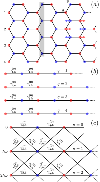
As depicted in Fig. 1(a), we consider a single phonon mode characterized by a rigid displacement between sublattices A and B, where sets the strength of the displacement and its direction. 111Throughout this work we will assume a longitudinal optical mode, such that . The positions of the carbon atoms thus depend on which sublattice they belong, i.e. , for , respectively. Assuming small displacements, i.e. , we linearize the hoppings as , where is the angle subtended by the C-C bond and the displacement direction. Now we impose quantization on the mechanical coordinate, such that the above hoppings introduce the electron-phonon interaction. The full Hamiltonian therefore reads
| (2) |
where () creates (annihilates) one phonon excitation of frequency , and sets the strength of the e-ph interaction. The pure electronic Hamiltonian is given by the C-C hoppings in equilibrium, and writes as in Eq. (1) but with the replacement . In Eq. (2) we also included the phonon Hamiltonian, given by
| (3) |
We work within a Fock space spanned by states, where describes a single electron state (usually referred to the site basis), while sets the number of phonon excitations in the lattice. In this basis, the Hamiltonian of Eq. (2) can be represented as the following matrix:
| (4) |
Here, and are electronic matrices representing the and hoppings in the hexagonal graphene lattice, and are the identity matrices in phonon and electron subspaces, respectively, while the remaining phonon matrices are defined as:
| (5) |
Expressed in the Fock space basis, the Hamiltonian in Eq. (4) can be visualized as the original one without interactions together with the replicas corresponding to different phonon excitations and the interactions between them. The presence of these excitations is accounted for by the additional energies . In this representation, the e-ph coupling enters through the last term, which enables the absorption and emission of a single phonon each time the electron ‘hops’ between two carbon atoms.
III Electron-phonon induced edge states
As introduced in the previous section, here we consider a fully quantized vibrational mode of frequency , and describe the vibrating nanoribbons through a Fock space spanned by the states , which accounts for both the electronic and vibrational degrees of freedom.
This might remind the reader of a similar picture used for time-periodic Hamiltonians: Floquet theory. Kohler et al. (2005) Indeed, there are several parallels stemming from a seeming isomorphism between the Floquet space and the Fock space, Shirley (1965) but a few crucial differences must be noticed: (i) Unlike for the case of time-dependent potentials, for the case of phonons, temperature plays a natural role in defining the phonon population. (ii) In Floquet theory, the replica index is unbound while in the case of phonons described here it is bounded from below (). (iii) The matrix elements for phonon emission and absorption change with the phonon population. Both descriptions (i.e. Fock space and Floquet space) match only when the system is in a highly excited state, a fact that is far from correct for optical phonons with typical energies exceeding at room temperature. Aside from these differences, inspired from what we learned from Floquet topological states, Oka and Aoki (2009); Lindner et al. (2011); Perez-Piskunow et al. (2014) one might then search for similar physics induced by the electron-phonon interaction.
Another issue one might notice is the role of time-reversal symmetry (TRS): While a gap in irradiated graphene requires circularly polarized light so as to break TRS, Oka and Aoki (2009); Calvo et al. (2011) 222We note the laser-induced bandgap opening has been experimentally observed through ARPES at the surface of a three-dimensional topological insulator Wang et al. (2013). the phonons considered here do not break such a symmetry (though they do open a bandgap Foa Torres and Roche (2006, 2007); Foa Torres et al. (2008) at in the bulk material). However, one needs also to point out that in this work we are restricting ourselves to a ribbon geometry (i.e. a quasi one-dimensional system) rather than a two-dimensional system. Interestingly, chiral phonons, Zhang and Niu (2015); Zhu et al. (2018) lying at the corners of the Brillouin zone, could be used in two-dimensional hexagonal lattices to break TRS (at least locally in the valleys). Carrying on with the Fock-Floquet analogy, one could expect in the latter case similar physics as that of irradiated graphene with circularly polarized light.
III.1 Vibration induced bandgaps
The proposed vibration of the lattice consists in a single mode characterized by a rigid displacement between the two sublattices. We will work in the case where the displacement direction coincides with the longitudinal direction of the ribbon, i.e. , motivated by the strong e-ph coupling observed in the optical mode in CNTs leading to a Peierls-like mechanism Dubay et al. (2002); Dubay and Kresse (2003); Connétable et al. (2005) and Kohn anomalies; Farhat et al. (2007) and also in graphene samples. Pisana et al. (2007)
To begin with, we consider a graphene nanoribbon with armchair edge geometry (ac-GNR). The reason of this particular choice rests in the possibility it offers to decompose the system into a series of decoupled eigenmodes. To do so, we start from the non-interacting case () and we use the basis transformation proposed in Ref. [Rocha et al., 2010]. This transformation takes the ac-GNR into a series of eigenmodes, each one consisting on a dimer chain with alternating hoppings and , with the mode number [see Fig. 1(b)]. In this sense, one can identify each eigenmode as an independent Su-Schrieffer-Heeger (SSH) model, Su et al. (1979) for which the topological properties are well-known. Fefferman et al. (2014); Li et al. (2014); Asbóth et al. (2016) Furthermore, the SSH model for time-dependent hoppings was also investigated in the context of Floquet topological states, both theoretically Gómez-León and Platero (2013); Asbóth et al. (2014); Dal Lago et al. (2015); Zhu et al. and experimentally. Cheng et al.
When including the e-ph interaction, we can extend this mode decomposition in the Fock space, such that for each eigenmode we obtain a series of dimer chains (or replicas of the non-interacting case), each one belonging to a different number of phonon excitations, see Fig. 1(c). This is easy to see regarding the structure of the Fock Hamiltonian in Eq. (4), where and commute with each other for this particular ribbon geometry and phonon mode. So, for a given mode , the intrachain hoppings alternate between and , as in the non-interacting case. The phonon energy in the -replica enters as a site energy along the whole chain, according to the second term in the r.h.s. of Eq. (4); and the interchain hoppings connecting the and replicas are given by and .
The degree of complexity imposed by the interaction clearly difficults the possibility of having analytic solutions for the system. However, the assumed weak coupling between the replicas () allows us to estimate the effects of the vibration on the electronic band structure by using perturbation theory around half the phonon energy. Other quantities like the local density of states (LDoS), eigenenergy spectrum and wavefunction amplitudes will be addressed numerically through standard techniques.
To begin with, we neglect the coupling between the different phonon replicas, such that the -dispersion relation at zeroth order can be written as:
| (6) |
This equation represents the band dispersion one would obtain for a dimer chain with unit cell length , but shifted in an integer number of , which accounts for the phonons energy. Among the infinite number of replicas, we will take as reference the lowest energy bands belonging to the zero-phonon subspace. This is justified for optical phonons with energies largely exceeding the thermal energy at room temperature (the stretching mode in graphene has a phonon energy of about meV, this is about times the thermal energy at K). Hence, the phonon population is zero for practical purposes. According to Eq. (6), the number of replicas crossing each other will depend on the relation between the phonon energy and the bandwidth associated with each replica, given by for .
For , the distance between bands belonging to different replicas is much larger than their widths and, therefore, they do not cross each other. In this limit, the perturbation on the zero-phonon replica due to replicas with a higher number of phonons becomes negligible: The electron lying in a lattice without phonons can never reach enough energy as to spontaneously emit a phonon.
The symmetry between the conduction () and valence bands with respect to for and ensures that the band crossing takes place at half the phonon energy, . This fact, together with the maximum allowed energy for the zero-phonon band, imposes the condition for the first band crossing between two different phonon replicas. In general, for smaller values of , the zero-phonon replica will cross with the phonon replica once the condition is fulfilled.

The eigenmode decomposition allows us to simplify the analysis around the band crossing processes. As in this particular geometry they are decoupled, the only relevant crossings are those with the same value of . We can think, then, in the crossing between and bands belonging to the eigenmode . To have such a crossing, it is necessary that the conduction band and the valence band overlap, which imposes the following range:
| (7) |
If such inequality can not be met, then the bands do not cross each other, and the zero-phonon replica gets virtually unperturbed. Conversely, if such inequality is fulfilled, the bands will cross at the -points determined by the condition . This equation has two solutions, , due to the symmetric dispersion of the bands in Eq. (6) around . When we include the e-ph interaction through , the crossing between the bands gets avoided, yielding a gap induced by the vibration. For these the group velocity goes to zero, meaning that a new backscattering process was introduced. From the point of view of the replica, an electron traveling in a static ribbon 333We here neglect the zero point motion of the lattice with energy may suffer a reflection, together with the emission of a phonon of energy . Alternatively, from the point of view of the replica, an electron traveling in a vibrating ribbon, such that the composite e-ph system has energy , may also be reflected, after absorption of the phonon excitation present in the lattice.
Supposing the limit case , we can take the cosine argument in as a continuous variable in the range . Under the perturbative regime, we estimate the bandgap size from a reduced Hamiltonian which only includes those bands which are expected to cross (see App. A). The size of the gap, as a function of , writes:
| (8) |
where and . In Fig. 2 we show this vibration induced bandgap for several values of the phonon frequency in the limit . To some extent, one can regard this limit as taking the nanoribbon into a two-dimensional graphene layer. Here, the set of eigenmodes becomes dense, meaning that there is always a specific -value in which the vibration induced gap necessarily closes. This is a consequence of the preserved TRS by the phonon mode. Going back to the finite system, the set of -values is no longer dense, and the overall gap will be given by the -mode closest to . This somewhat relaxes the need to break TRS as to open a gap in quasi one-dimensional systems.
We notice that Eq. (8) has physical meaning as long as the argument of the square root is positive. This sets the condition for those eigenmodes in which there is a band crossing, and it results to be for and for , in agreement with Eq. (7). On the other hand, the bandgap size depends linearly on , and there is also some dependence with the phonon frequency through the parameter. Interestingly, while for semiconducting GNRs the bandgap around the central region can only be closed by increasing , the vibration induced bandgap could be controlled, to some extent, through the modulation of the e-ph coupling. Dutreix and Katsnelson (2017) We can, in turn, determine the maximum value of the gap as a function of . This yields two regimes: (i) for , a frequency independent regime with maximum gap , and (ii) for , a frequency dependent regime where the maximum gap decreases and it closes in the limit .
III.2 Spectral properties and characterization of the edge states
Throughout the following analysis we will consider a high-frequency regime by choosing . 444For the chosen value , the band crossings occur for those eigenmodes fulfilling . For this value, the conduction band belonging to the zero-phonon replica only cross with the valence band of the one-phonon replica, since the condition can only be fullfilled by . Although the chosen largely exceeds the typical phonon energy of the optical mode, this high-frequency regime, together with the weak e-ph coupling assumption (), allows us to truncate the infinite Fock space in the first two phonon replicas, thereby simplifying the discussion of the vibration effects on the electronic properties of the ribbon. In particular, this ensures both the valence band () and the semiconducting gap () regions being unaffected by the vibration, at least in lowest order in the e-ph coupling. This allows us to establish a clear distinction between the well-known “native” edge-states Delplace et al. (2011) at , and the expected e-ph induced edge-states, located at . In any case, the same analysis can be carried out for meV, but keeping in mind that a competition between the native topology and the e-ph induced edge states may occur near the charge neutrality point. Dal Lago et al. (2015)
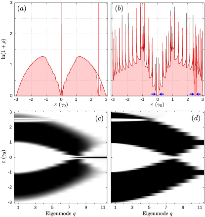
In Fig. 3(a) we show the LDoS weighted over the zero-phonon replica (red shaded area), evaluated at the lateral border of a semi-infinite ac-GNR of carbon atoms wide (). Except for some region around , the shape of the LDoS is qualitatively the same as that of the non-interacting case (solid black), with a central peak related with the native edge states. This is expected as the e-ph interaction only becomes effective in the band crossing region at . Here, we observe a similar behavior as in the region, i.e. a depletion in the LDoS with a pronounced peak rising in its center.
To infer whether the peak at survives far away from the border of the ribbon, we show in Fig. 3(b) the zero-phonon LDoS evaluated at the center of an infinite ac-GNR. The pronounced peaks at and are no longer visible, and instead we can observe bandgap openings around these energies (blue arrows). For this is the e-ph interaction induced bandgap, which was also predicted in vibrating CNTs. Foa Torres and Roche (2006, 2007); Foa Torres et al. (2008) As it is expressed in Eq. (8), the size of the vibration induced gap depends on the eigenmode we are looking at, which is observed in the LDoS maps of Figs. 3(c) and (d). For the chosen values and , the band crossings occur for those eigenmodes fulfilling . The minimum gap occurs for the mode with closest to , which in this case is . Here, the effective interchain coupling between the phonon replicas [c.f. Eq. (16)] is the smallest, and it increases for smaller modes.
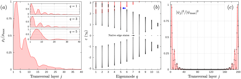
The absence of peaks in the bulk LDoS makes us suspect that, as in the case of the native edge states at , the peak at is also related with states localized at the ribbon’s border. Let us see, now, the behavior of the vibration induced peak as we move inside the ribbon. In Fig. 4(a) the zero-phonon LDoS evaluated at half the phonon energy is shown as a function of the transversal layer number [vertical lines of carbon atoms, see Fig. 1(a)]. The LDoS decays exponentially, such that for it becomes negligible. The way in which the peak decays is quite irregular, due to the superposition of the contributing tranversal modes (see inset plots in the figure).
To characterize the eigenenergy spectrum and the localized state wavefunctions we now consider a finite ac-GNR of carbon atoms long () and wide (). In Fig. 4(b) we show the eigenenergy spectrum resolved in eigenmodes. To visualize such a spectrum as a perturbation of that in the non-interacting case, we weight each eigenstate over the replica, i.e. the zero-phonon subspace. Given a -eigenstate belonging to the eigenmode , we can decompose it as the following superposition among the replicas according to:
| (9) |
and take its projection over the subspace, i.e.
| (10) |
Although the number of replicas is infinite, the fact that we work in a perturbative regime allows us to truncate the full Fock space in a few replicas. In our case where and , the subspace associated with those replicas with has negligible impact on the replica. In Fig. 4(b), the red dots reveal how the valence band belonging to the replica mixes with the conduction band of the replica (black dots) for . Around this value, we can observe bandgap openings for those modes with , together with the presence of two degenerate midgap states per eigenmode (blue arrow).
In Fig. 4(c) we show one of the two midgap states for . As we move towards the center of the ribbon, the probability density oscillate according with the weights this particular -mode has on the sites composing the transversal layer. As it happens with the LDoS peak, the wavefunction also shows an exponential decay along the longitudinal direction, with a typical ‘inverse gap’ localization length. However, as the ribbon in this example has a finite length, the wavefunction has weight in the two borders. We can think of this state as bonding or antibonding combination of two states, and , localized at the left and the right border of the ribbon, respectively. For a ribbon with a large number of transversal layers (as it happens here), the overlap can be neglected and one can consider and as linear combinations of the two degenerate midgap states.
III.3 Topological origin of the edge states
As discussed before, when decreasing the phonon energy from on we will observe band crossings between different phonon replicas which, in turn, generate bandgap openings as new backscattering processes are introduced. This can be regarded as a band inversion process: In the crossing region, the valence band from the replica happens to have less energy than that of the conduction band from the replica. This band inversion is characteristic in topological phase transitions, together with the formation of localized midgap states. This strongly motivates the calculation of the Zak phase to infer about the topological nature of the vibration induced localized states. Although there is an infinite number of bands due to the structure of the Fock space, we can again truncate this by taking only those bands belonging to the and replicas. The corresponding topological invariant can be calculated as the integral of the Berry connection Zak (1989)
| (11) |
with the Bloch states belonging to the -band and the integral taken over the first Brillouin zone. The bulk-boundary correspondence then allows us to characterize the existence of topological states with the Zak phase. Summing up for all the bands with energy below a given gap yields the cumulative phase (modulo ), which indicates the existence (with cumulative phase ) or absence (zero cumulative phase) of topological midgap states.
Although the Zak phase can be obtained analytically in the SSH model Asbóth et al. (2016) and graphene nanoribbons, Delplace et al. (2011) we here proceed with a numerical calculation of the invariant. Computationally speaking, the Zak phase involves the calculation of wavefunction amplitudes with some arbitrary gauge introduced by the diagonalization algorithm. In consequence, their possible outcomes, i.e. or , do not fully determine the band topology. However, one can infer its topology from the variation of with respect to a reference case in which such a phase is known. In the previous sections, we concluded that for very high phonon energies, given by the condition , there are no band crossings, and in consequence the zero-phonon replica remains unperturbed. This high-frequency limit represents our reference case, where the Zak phase is well known for all band replicas.
| 1 | 2 | 3 | 4 | 1 | 2 | 3 | 4 | |
| 1 | 0 | 0 | 0 | 0 | ||||
| 2 | 0 | 0 | 0 | 0 | ||||
| 3 | 0 | 0 | 0 | 0 | ||||
| 4 | 0 | 0 | 0 | 0 | ||||
| 5 | 0 | 0 | 0 | 0 | ||||
| 6 | 0 | 0 | 0 | 0 | 0 | 0 | ||
| 7 | 0 | 0 | 0 | 0 | 0 | 0 | ||
| 8 | 0 | 0 | ||||||
| 9 | 0 | 0 | ||||||
| 10 | ||||||||
| 11 | ||||||||
We show in Table 1 the Zak phases corresponding to the four bands belonging to replicas and for the phonon energies and . As can be seen from the table, in this example the role of the interaction is to open a gap between bands 2 and 3, and adding a factor to the band’s cumulative phase. For this implies that modes with host vibration induced topological states between bands 2 and 3, while modes with host native topological states in the gap between bands 1 and 2 (related with the zero-phonon replica) and between bands 3 and 4 (related with the phonon replica). For , the band crossing condition is fulfilled for . For these modes, the Zak phase for the lowest energy band (valence band of the replica) is equal to , which means that native edge states are present. However, more interesting is the case of the modes, where the topological invariant for the second lowest energy band is equal to zero (cumulative Zak phase of ), which implies that these modes host both native and vibrational induced topological states.
We therefore notice that the condition for the formation of interaction induced topological states is the band crossing, while the native states appear when the intracell hopping is smaller than the intercell hopping . Asbóth et al. (2016) As we shall see next, this difference in the formation of the native and interaction-induced topological states brings with it important consequences when evaluating the robustness of such states against changes in the ribbon geometry and the introduction of several types of disorder.
III.4 Ribbon geometries and robustness against disorder
So far we have been discussing the effects of the e-ph interaction on a particular ribbon geometry where the eigenmodes remain decoupled even in the presence of the vibration. It therefore becomes natural to ask whether the topological states survive in other geometries and, in turn, if they are robust against different types of disorder which might couple these eigenmodes. In this section we provide an answer to these questions by analysing the LDoS along the ribbon edges for different geometries and by incorporating either vacancy or impurity disorder.
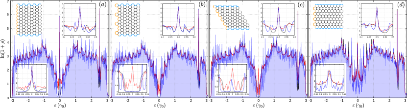
In Fig. 5 we show the LDoS evaluated around the edge region for different GNRs geometries. As in Fig. 3, we plot the quantity as to compensate the peaks height from the rest of the data. In these examples we considered randomly-generated vacancy disorder of over the complete sample. In all panels, we show the zero-phonon LDoS without disorder (solid black), a single disorder realization (shaded blue area), and an ensamble average over realizations (red line). The insets in each panel show zoom regions around (bottom inset) and (top inset) to help visualization, while the schemes describe the type of ribbon geometry, characterized by longitudinal (cyan) and transversal (orange) borders. In all cases we used to ensure a ribbon length much larger than the localization lengths of all edge states.
Comparing the panels in Fig. 5 we first notice that, in absence of vacancy disorder, the LDoS peak in can be present or not depending on the ribbon geometry. This is illustrated by the black lines in the figure (see bottom inset in each panel), where panels (b) and (c) show no peak at this energy, while in panels (a) and (d) such a peak is certainly visible. The peak in , on the other hand, is present in all panels. This important result allows for a clear distinction between the and the edge states. While the native states may appear or not depending on the particular ribbon geometry, the presence of topological states induced by the e-ph interaction is ensured by the crossing of conduction and valence bands belonging to different phonon replicas. For this reason we believe the native states are rather marginal: Although they admit a topological characterization through the Zak phase, their emergence is strictly determined by the ribbon’s geometry.
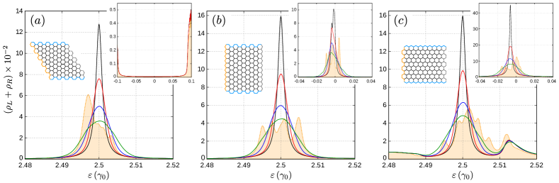
When we include a concentration of vacancies along the full sample, the main structure of the LDoS holds (blue lines), though it obviously displays a noisy pattern around the LDoS without disorder (black lines). Such a perturbative behavior can be tested by taking an ensamble average over several ribbon samples with the same vacancy concentration. The red lines show the LDoS averaged over realizations, and superimpose the LDoS without disorder along almost the entire spectrum. However, looking closer at in Figs. 5(b) and (c) (see bottom insets) we notice that, in average, the zero energy peak returns when vacancy disorder is included. The fact that the average LDoS (red) in Fig. 5(b) shows a peak at while the trial LDoS for a single realization (blue) shows no peak, and that this peak is present in both cases in Fig. 5(c) indicates that this is an intermittent effect: In those cases where the LDoS shows no central peak without disorder, when including disorder this peak may appear for some vacancy configurations. In fact, these peaks have nothing to do with the native edge states appearing in Figs. 5(a) and (d), but these are related to localized states that surround the vacancies in the sample. Pereira et al. (2006) Thus depending on the presence (or absence) of vacancies nearby the region where the LDoS is being evaluated one can see (or not) a peak in the LDoS. In the considered examples of Fig. 5(b) and (c), the region where the LDoS was evaluated involves 100 carbon atoms, and since the vacancy concentration is , one expects 0.5 vacancies in this region, so the chances of observing a peak in this region are one in two. Obviously, since the chances to have one or more localized states due to the presence of vacancies within the evaluation region grow with the vacancy concentration, we expect a simple relation between this quantity and the average height of the central peak. Having understood the role of disorder in the central peak of Figs. 5(b) and (c), we now observe that the shape and intensity of the central peak in Figs. 5(a) and (d) change little when including disorder, meaning that the native states, if present, are robust against moderate vacancy disorder. For the e-ph induced topological states we can arrive to the same conclusion, as the peaks in are all the same, regardless of the vacancy disorder.
We now investigate the role of impurity disorder on the ribbon’s LDoS. This is modeled through a random variation of the on-site energies within the range . This means that the pure electronic Hamiltonian in Eq. (2) is replaced by
| (12) |
with the random on-site energy. In Fig. 6 we show the LDoS around the e-ph band crossing point, centered at , together with the LDoS around the Dirac point at (insets). In these examples we evaluate the zero-phonon replica LDoS over 40 transversal layers of carbon atoms for both left and right borders, considered as mirror images each other. This was done for three ribbon geometries (see schemes in each panel), and we used (red), (blue), and (green). In these examples we calculated the average LDoS over 250 disorder realizations. Black lines exhibit the case without disorder (), while dotted orange lines (shaded area) illustrate the case of a single disorder realization for .
For the shown ribbon geometries, we can see that the e-ph induced LDoS peak at (dotted orange) now splits out into several peaks lying within the bandgap region. To understand why this type of disorder produces such an effect, first notice that the LDoS peak at without disorder (black lines) can be decomposed into several peaks, each one belonging to a topological edge state. The position of these peaks depends on the average of the on-site energies around the region where the probability density is finite. If we imagine the impurity disorder [first term in Eq. (12)] as a perturbation, and represents the wavefunction amplitude of the (unperturbed) e-ph induced topological state at position , then the energy (and thus the peak position in the LDoS) will depend on the on-site energies as:
| (13) |
which can be interpreted as the original position (i.e. without disorder), plus the -state weighted average of the on-site energies. As for the considered ribbon sizes the topological edge states have finite weight over a small number of sites, the last term in the above equation may not vanish in general. In fact, this quantity tends to increase with the degree of disorder . This is reflected as a broadening of the averaged LDoS peaks (solid red, blue, and green) when increases. Importantly, the area below the LDoS peak remains always constant, meaning that the number of topological states in the sample is independent of disorder. Of course, though does not change the number of topological states, for larger values these states may be located in energy regions outside the overall gap, thus difficulting a clear separation between localized and extended states.
The same disorder-induced peak broadending can be observed in the central region around (see insets), but it is important to notice that, as in the vacancy disorder case, the native states can be present or not depending on the ribbon geometry. Additionally, due to the zoom factor, one can observe that the average peaks are not perfectly centered at , but slightly shifted to the left. This is not related to disorder (the black line peaks are also shifted) but a second order effect in the coupling between the zero- and one-phonon replica bands.
IV Summary and final remarks.
In summary, we have shown that novel and robust states of topological origin form as a consequence of the electron-phonon interaction in graphene nanoribbons. This study, based on a specific model for the electron-phonon interaction given by a stretching mode in graphene nanoribbons, serves as a proof of concept. The topological states form at the center of a bandgap (induced by the same interaction) located at half the phonon energy above the charge neutrality point. This was confirmed in several ribbon geometries and for vacancy and impurity disorder configurations. While both the native and the e-ph induced states were characterized through the Zak phase, and shown to be robust against disorder, the native states only appear in some specific ribbon geometries. Conversely, for a non-negligible e-ph interaction, the presence of the vibration induced topological states is guaranteed as long as the phonon energy does not exceed the typical band width, i.e. . Such a condition provides the required band inversion between the first two phonon replicas.
Interestingly, this physics happens in our case even when the phonons do not break time-reversal symmetry, similar to a driven one-dimensional topological insulator. Dal Lago et al. (2015) In two dimensional systems, however, the e-ph induced bandgap finally closes for some particular mode (see discussion on the limit around Fig. 2) and one should break TRS to restore the gap (as it is required for light to induce Floquet topological states in the same material). In this sense, the recent observation of chiral phonons in two-dimensional materials Zhu et al. (2018) may open a promising way for studying electron-phonon induced topological phase transitions.
Acknowlegdments.– This work was supported by Consejo Nacional de Investigaciones Científicas y Técnicas (CONICET), Secretaría de Ciencia y Tecnología – Universidad Nacional de Córdoba (SECYT–UNC). HLC and JSL are members of CONICET. LEFFT acknowledges funding from Program “Instalación Académica” 2016 of the Faculty of Physical and Mathematical Sciences of the University of Chile and FondeCyT (Chile) under project number 1170917.
Appendix A Vibration induced bandgaps
Let us think of two replicas (zero- and one-phonon) of a dimer chain for a particular eigenmode (see Fig. 1). Each dimer chain develops a valence and a conduction band, and the energy difference between the two replicas is . Let us suppose that is small enough such that the conduction band and the valence band cross. If denotes the Bloch quasimomentum, there are two -values () where the band crossing occurs. If we focus on one of these points, say , we have two -states at the same energy, each one belonging to one of the two replicas. This degeneration gets removed by the electron-phonon interaction, which in our case corresponds to the coupling between the replicas, and yields the bandgap opening. In this appendix we estimate the gap size produced by the e-ph interaction.
When using the eigenmode decomposition, the hopping term between sites depends on the mode we are looking at, with a factor , and . We take the cosine argument as a continuous variable , within the range , and we simplify this analysis by truncating the full Fock space so we only keep the and replicas. Considering the bulk situation (i.e. an infite long dimer chain) we can use Bloch theorem and obtain the following Hamiltonian:
| (14) |
where
| (15) |
with the unit cell length, and the bar standing for complex conjugation. Since we are only interested in the conduction and valence bands, we can reduce even more this Hamiltonian. To do so, we first diagonalize the block matrices in the diagonal. As they commute each other, we can diagonalize the block, and obtain the energies . Similarly, for the block we obtain . The next step is to write the Bloch Hamiltonian in this new basis, such that it allows the proper truncation
| (16) |
where . This Hamiltonian has the following eigenvalues
| (17) |
With these expressions, we found the new eigenenergies for close to the band crossing point. We can, in turn, particularize to the point in which this band crossing occurs and obtain an expression for the size of the gap . Recalling that the band crossing takes place at , we take equal to this energy, and using the definitions for given in Eq. (15), we obtain
| (18) |
By finding the -value for which is satisfied, and defining the adimensional parameter , we obtain that the size of the e-ph interaction induced bandgap is given by
| (19) |
where . The size of the gap will depend, therefore, on this parameter and the particular eigenmode (through the -variable) we are looking at. The square root argument defines the band crossing regimes, as this quantity needs to be always positive. This yields the condition
| (20) |
which is equivalent to Eq. (7) of the main text.
References
- Hasan and Kane (2010) M. Z. Hasan and C. L. Kane, “Topological insulators,” Rev. Mod. Phys. 82, 3045 (2010).
- Ortmann et al. (2015) F. Ortmann, S. Roche, and S. O. Valenzuela, eds., Topological Insulators: Fundamentals and Perspectives (Wiley, 2015).
- Thouless et al. (1982) D. J. Thouless, M. Kohmoto, M. P. Nightingale, and M. den Nijs, “Quantized Hall conductance in a two-dimensional periodic potential,” Phys. Rev. Lett. 49, 405 (1982).
- Haldane (1988) F. D. M. Haldane, “Model for a quantum Hall effect without Landau levels: Condensed-matter realization of the “parity anomaly”,” Phys. Rev. Lett. 61, 2015 (1988).
- Kane and Mele (2005) C. L. Kane and E. J. Mele, “Quantum spin Hall effect in graphene,” Phys. Rev. Lett. 95, 226801 (2005).
- Bernevig et al. (2006) B. A. Bernevig, T. L. Hughes, and S.-C. Zhang, “Quantum spin Hall effect and topological phase transition in HgTe quantum wells,” Science 314, 1757 (2006).
- König et al. (2007) M. König, S. Wiedmann, C. Brüne, A. Roth, H. Buhmann, L. W. Molenkamp, X.-L. Qi, and S.-C. Zhang, “Quantum spin Hall insulator state in HgTe quantum wells,” Science 318, 766 (2007).
- Hsieh et al. (2008) D. Hsieh, D. Qian, L. Wray, Y. Xia, Y. S. Hor, R. J. Cava, and M. Z. Hasan, “A topological Dirac insulator in a quantum spin Hall phase,” Nature 452, 970 (2008).
- Yan and Felser (2017) B. Yan and C. Felser, “Topological materials: Weyl semimetals,” Annu. Rev. Condens. Matter Phys. 8, 337 (2017).
- Oka and Aoki (2009) T. Oka and H. Aoki, “Photovoltaic Hall effect in graphene,” Phys. Rev. B 79, 081406 (2009).
- Lindner et al. (2011) N. H. Lindner, G. Refael, and V. Galitski, “Floquet topological insulator in semiconductor quantum wells,” Nat. Phys. 7, 490 (2011).
- Sentef et al. (2015) M. A. Sentef, M. Claassen, A. F. Kemper, B. Moritz, T. Oka, J. K. Freericks, and T. P. Devereaux, “Theory of Floquet band formation and local pseudospin textures in pump-probe photoemission of graphene,” Nat. Commun. 6, 7047 (2015).
- Iadecola et al. (2014) T. Iadecola, T. Neupert, and C. Chamon, “Topological gaps without masses in driven graphene-like systems,” Phys. Rev. B 89, 115425 (2014).
- Shen et al. (2018) H. Shen, B. Zhen, and L. Fu, “Topological band theory for non-Hermitian Hamiltonians,” Phys. Rev. Lett. 120, 146402 (2018).
- Martinez Alvarez et al. (2018) V. M. Martinez Alvarez, J. E. Barrios Vargas, and L. E. F. Foa Torres, “Non-Hermitian robust edge states in one dimension: Anomalous localization and eigenspace condensation at exceptional points,” Phys. Rev. B 97, 121401 (2018).
- Basov et al. (2017) D. N. Basov, R. D. Averitt, and D. Hsieh, “Towards properties on demand in quantum materials,” Nat. Mater. 16, 1077 (2017).
- Reijnders et al. (2014) A. A. Reijnders, Y. Tian, L. J. Sandilands, G. Pohl, I. D. Kivlichan, S. Y. F. Zhao, S. Jia, M. E. Charles, R. J. Cava, N. Alidoust, S. Xu, M. Neupane, M. Z. Hasan, X. Wang, S. W. Cheong, and K. S. Burch, “Optical evidence of surface state suppression in Bi-based topological insulators,” Phys. Rev. B 89, 075138 (2014).
- Garate (2013) I. Garate, “Phonon-induced topological transitions and crossovers in Dirac materials,” Phys. Rev. Lett. 110, 046402 (2013).
- Saha and Garate (2014) K. Saha and I. Garate, “Phonon-induced topological insulation,” Phys. Rev. B 89, 205103 (2014).
- Kim and Jhi (2015) J. Kim and S.-H. Jhi, “Topological phase transitions in group IV-VI semiconductors by phonons,” Phys. Rev. B 92, 125142 (2015).
- Antonius and Louie (2016) G. Antonius and S. G. Louie, “Temperature-induced topological phase transitions: Promoted versus suppressed nontrivial topology,” Phys. Rev. Lett. 117, 246401 (2016).
- Foa Torres and Roche (2006) L. E. F. Foa Torres and S. Roche, “Inelastic quantum transport and Peierls-like mechanism in carbon nanotubes,” Phys. Rev. Lett. 97, 076804 (2006).
- Foa Torres et al. (2008) L. E. F. Foa Torres, R. Avriller, and S. Roche, “Nonequilibrium energy gaps in carbon nanotubes: Role of phonon symmetries,” Phys. Rev. B 78, 035412 (2008).
- Pisana et al. (2007) S. Pisana, M. Lazzeri, C. Casiraghi, K. S. Novoselov, A. K. Geim, A. C. Ferrari, and F. Mauri, “Breakdown of the adiabatic Born-Oppenheimer approximation in graphene,” Nat. Mater. 6, 198 (2007).
- Zhu et al. (2018) H. Zhu, J. Yi, M.-Y. Li, J. Xiao, L. Zhang, C.-W. Yang, R. A. Kaindl, L.-J. Li, Y. Wang, and X. Zhang, “Observation of chiral phonons,” Science 359, 579 (2018).
- Hübener et al. (2018) H. Hübener, U. De Giovannini, and A. Rubio, “Phonon driven Floquet matter,” Nano Lett. 18, 1535 (2018).
- Dutreix and Katsnelson (2017) C. Dutreix and M. I. Katsnelson, “Dynamical control of electron-phonon interactions with high-frequency light,” Phys. Rev. B 95, 024306 (2017).
- Anda et al. (1994) E. V. Anda, S. S. Makler, H. M. Pastawski, and R. G. Barrera, “Electron-phonon effects on transport in mesoscopic heterostructures,” Braz. J. Phys. 24, 330 (1994).
- Bonča and Trugman (1995) J. Bonča and S. A. Trugman, “Effect of inelastic processes on tunneling,” Phys. Rev. Lett. 75, 2566 (1995).
- Mingo and Makoshi (2000) N. Mingo and K. Makoshi, “Calculation of the inelastic scanning tunneling image of acetylene on Cu(100),” Phys. Rev. Lett. 84, 3694 (2000).
- Ness and Fisher (1999) H. Ness and A. J. Fisher, “Quantum inelastic conductance through molecular wires,” Phys. Rev. Lett. 83, 452 (1999).
- Emberly and Kirczenow (2000) E. G. Emberly and G. Kirczenow, “Landauer theory, inelastic scattering, and electron transport in molecular wires,” Phys. Rev. B 61, 5740 (2000).
- Foa Torres et al. (2001) L. E. F. Foa Torres, H. M. Pastawski, and S. S. Makler, “Tuning a resonance in Fock space: Optimization of phonon emission in a resonant-tunneling device,” Phys. Rev. B 64, 193304 (2001).
- Pereira et al. (2009) V. M. Pereira, A. H. Castro Neto, and N. M. R. Peres, “Tight-binding approach to uniaxial strain in graphene,” Phys. Rev. B 80, 045401 (2009).
- Note (1) Throughout this work we will assume a longitudinal optical mode, such that .
- Kohler et al. (2005) S. Kohler, J. Lehmann, and P. Hänggi, “Driven quantum transport on the nanoscale,” Phys. Rep. 406, 379 (2005).
- Shirley (1965) J. H. Shirley, “Solution of the Schrödinger equation with a Hamiltonian periodic in time,” Phys. Rev. 138, B979 (1965).
- Perez-Piskunow et al. (2014) P. M. Perez-Piskunow, G. Usaj, C. A. Balseiro, and L. E. F. Foa Torres, “Floquet chiral edge states in graphene,” Phys. Rev. B 89, 121401(R) (2014).
- Calvo et al. (2011) H. L. Calvo, H. M. Pastawski, S. Roche, and L. E. F. Foa Torres, “Tuning laser-induced band gaps in graphene,” Appl. Phys. Lett. 98, 232103 (2011).
- Note (2) We note the laser-induced bandgap opening has been experimentally observed through ARPES at the surface of a three-dimensional topological insulator Wang et al. (2013).
- Foa Torres and Roche (2007) L. E. F. Foa Torres and S. Roche, “Electron-phonon induced conductance gaps in carbon nanotubes,” Appl. Phys. A 86, 283 (2007).
- Zhang and Niu (2015) L. Zhang and Q. Niu, “Chiral phonons at high-symmetry points in monolayer hexagonal lattices,” Phys. Rev. Lett. 115, 115502 (2015).
- Dubay et al. (2002) O. Dubay, G. Kresse, and H. Kuzmany, “Phonon softening in metallic nanotubes by a Peierls-like mechanism,” Phys. Rev. Lett. 88, 235506 (2002).
- Dubay and Kresse (2003) O. Dubay and G. Kresse, “Accurate density functional calculations for the phonon dispersion relations of graphite layer and carbon nanotubes,” Phys. Rev. B 67, 035401 (2003).
- Connétable et al. (2005) D. Connétable, G.-M. Rignanese, J.-C. Charlier, and X. Blase, “Room temperature Peierls distortion in small diameter nanotubes,” Phys. Rev. Lett. 94, 015503 (2005).
- Farhat et al. (2007) H. Farhat, H. Son, G. G. Samsonidze, S. Reich, M. S. Dresselhaus, and J. Kong, “Phonon softening in individual metallic carbon nanotubes due to the Kohn anomaly,” Phys. Rev. Lett. 99, 145506 (2007).
- Rocha et al. (2010) C. G. Rocha, L. E. F. Foa Torres, and G. Cuniberti, “ac transport in graphene-based Fabry-Pérot devices,” Phys. Rev. B 81, 115435 (2010).
- Su et al. (1979) W. P. Su, J. R. Schrieffer, and A. J. Heeger, “Solitons in polyacetylene,” Phys. Rev. Lett. 42, 1698 (1979).
- Fefferman et al. (2014) C. L. Fefferman, J. P. Lee-Thorp, and M. I. Weinstein, “Topologically protected states in one-dimensional continuous systems and Dirac points,” Proc. Natl. Acad. Sci. U. S. A. 111, 8759 (2014).
- Li et al. (2014) L. Li, Z. Xu, and S. Chen, “Topological phases of generalized Su-Schrieffer-Heeger models,” Phys. Rev. B 89, 085111 (2014).
- Asbóth et al. (2016) J. K. Asbóth, L. Oroszlány, and A. Pályi, A Short Course on Topological Insulators (Springer, 2016).
- Gómez-León and Platero (2013) A. Gómez-León and G. Platero, “Floquet-Bloch theory and topology in periodically driven lattices,” Phys. Rev. Lett. 110, 200403 (2013).
- Asbóth et al. (2014) J. K. Asbóth, B. Tarasinski, and P. Delplace, “Chiral symmetry and bulk-boundary correspondence in periodically driven one-dimensional systems,” Phys. Rev. B 90, 125143 (2014).
- Dal Lago et al. (2015) V. Dal Lago, M. Atala, and L. E. F. Foa Torres, “Floquet topological transitions in a driven one-dimensional topological insulator,” Phys. Rev. A 92, 023624 (2015).
- (55) B. Zhu, H. Zhong, Y. Ke, X. Qin, A. A. Sukhorukov, Y. S. Kivshar, and C. Lee, “Topological Floquet edge states in periodically curved waveguides,” arXiv:1804.03772 [physics.optics] .
- (56) Q. Cheng, Y. Pan, H. Wang, C. Zhang, D. Yu, A. Gover, H. Zhang, T. Li, L. Zhou, and S. Zhu, “Observation of anomalous modes in photonic Floquet engineering,” arXiv:1804.05134 [quant-ph] .
- Note (3) We here neglect the zero point motion of the lattice.
- Note (4) For the chosen value , the band crossings occur for those eigenmodes fulfilling .
- Delplace et al. (2011) P. Delplace, D. Ullmo, and G. Montambaux, “Zak phase and the existence of edge states in graphene,” Phys. Rev. B 84, 195452 (2011).
- Zak (1989) J. Zak, “Berry’s phase for energy bands in solids,” Phys. Rev. Lett. 62, 2747 (1989).
- Pereira et al. (2006) V. M. Pereira, F. Guinea, J. M. B. Lopes dos Santos, N. M. R. Peres, and A. H. Castro Neto, “Disorder induced localized states in graphene,” Phys. Rev. Lett. 96, 036801 (2006).
- Wang et al. (2013) Y. H. Wang, H. Steinberg, P. Jarillo-Herrero, and N. Gedik, “Observation of Floquet-Bloch states on the surface of a topological insulator,” Science 342, 453 (2013).