Intrinsic energy spread and bunch length growth in plasma-based accelerators due to betatron motion
Abstract
Plasma-based accelerators (PBAs), having demonstrated the production of GeV electron beams in only centimetre scales, offer a path towards a new generation of highly compact and cost-effective particle accelerators. However, achieving the required beam quality, particularly on the energy spread for applications such as free-electron lasers, remains a challenge. Here we investigate fundamental sources of energy spread and bunch length in PBAs which arise from the betatron motion of beam electrons. We present an analytical theory, validated against particle-in-cell simulations, which accurately describes these phenomena. Significant impact on the beam quality is predicted for certain configurations, explaining previously observed limitations on the achievable bunch length and energy spread. Guidelines for mitigating these contributions towards high-quality beams are deduced.
Introduction
In plasma-based accelerators (PBAs), an intense laser pulse [1] or high-energy charged particle beam [2] drives a plasma wake sustaining accelerating fields orders of magnitude higher than those achievable with conventional radiofrequency technology [3], offering a path towards highly compact and cost-effective accelerators. Having reached GeV energies in only centimeter scales [4, 5, 6, 7, 8], femtosecond-long electron bunches with kiloampere current [9, 10] and micron-level emittance [11, 12], PBAs are becoming increasingly attractive for applications such as free-electron lasers (FELs) [13] or future linear colliders [14], which would strongly benefit from reduced size and cost. In particular, there is also a special interest in the production of sub-femtosecond bunches [15, 16, 17] to generate short X-ray pulses for ultrafast science [18].
However, despite these major advances, achieving an energy spread below the percent level has remained an issue. This is a problem not only for applications such as FELs, which require a relative energy spread [19], but also for the beam transport after the plasma, which could cause a dramatic emittance growth [20] and further reduce the beam quality, limiting any kind of multi-stage acceleration. Although the impact on the emittance can be mitigated by tailored plasma-to-vacuum transitions [21] or the use of active plasma lenses instead of conventional quadrupoles [22], improving the beam parameters in the plasma is essential for demanding applications. Major efforts have therefore been dedicated towards this objective, including the development of controlled injection techniques [23, 24, 25, 26, 27] as well as concepts for mitigating the correlated energy spread arising from the steep slope of the accelerating fields. These include beam loading the wake [28, 29, 30], either by the accelerated bunch itself [31] or the injection of a secondary one[32], the use of modulated [33] or tailored [34] plasma profiles, the insertion of a magnetic chicane in a multistage PBA [35], or taking advantage of the beam-induced wakefields [36, 37, 38, 39, 40].
Here we describe additional sources of energy spread in PBAs which should also be mitigated, as well as limitations on the minimum achievable bunch length. In particular, we show that the transverse oscillations of beam electrons (known as betatron motion), induced by the strong focusing fields in the plasma wake, can be a significant source of uncorrelated (or slice) energy spread as well as increased bunch length due to path length differences between particles with different oscillation amplitude. Although these effects were already known [41, 42], no model exists to date for their impact on the beam parameters. We present here a novel analytical theory, validated against numerical simulations with the particle-in-cell (PIC) codes OSIRIS [43] and HiPACE [44], which accurately describes these phenomena in the assumption of relativistic electrons in a non-evolving wake. This model allows us to understand previously observed limitations, such as a finite energy spread even when the initial bunch length approaches zero [45], and define guidelines for minimizing the impact of these phenomena for high-quality electron beams.
Results
Development of a single-particle model
As a first step, a single-particle model capable of describing the coupling of the transverse oscillations into the longitudinal motion is needed. Then, from this model, statistical averages over a particle beam can be analytically obtained in order to determine the impact of this coupling on parameters such as the energy spread and bunch length.
For a relativistic particle moving close to the speed of light , the longitudinal component of its velocity , where is the magnitude of the particle velocity , is limited by and can be decreased due to motion in the transverse planes, i.e, if . Thus, in the speed-of-light frame , where is the longitudinal coordinate in the laboratory frame and is the time, a particle performing betatron oscillations will experience a slippage towards the back which, at a time , will be given by , where is its initial position and is its longitudinal velocity in the speed of light frame.
Determining the particle slippage thus requires obtaining an expression for , which, in turn, depends on the evolution of the transverse components and . In order to find these expressions, the equations of motion of a relativistic electron in a plasma wakefield have to be solved. These are given by , where is the particle momentum, is the electron mass, is the relativistic Lorentz factor of the particle, is the elementary charge and is the wakefield. In this expression, and (for ) are the different components of the electric and magnetic fields. Analytical expressions of the wakefields can be found for the linear regime [46, 47], and several models have been developed for non-linear wakes in the blowout regime [48, 49]. In what follows, the wakefield gradients around the particle, , and , will be assumed constant and for . This is especially well-suited for the blowout regime, where the driver expels all plasma electrons and leaves behind an ion cavity with uniform focusing fields and an approximately constant in a wide range of the accelerating phase. The plasma frequency is defined as , where is the vacuum permittivity and is the unperturbed plasma density. For linear wakes, although these gradients are not uniform, this model can be applied for regions sufficiently close to the propagation axis, where and can be regarded as constant, and if , so that the longitudinal change in , and can be neglected.
Under these conditions, the equations of motion for a beam electron in a non-evolving wake with a phase velocity given by the propagation velocity of the driver, can be written as
| (1) | ||||
| (2) |
where , is the betatron frequency and . Since is assumed constant, then , with . Using this expression in Eq. (1) yields , where , with , is the energy evolution assuming constant acceleration and accounts for the contribution of slippage and dephasing with respect to the wake [50]. If , then can be assumed in order to solve Eq. (2), for which analytical solutions can be found if is a slowly varying function [51], i.e, if . This yields the following expressions:
| (3) | ||||
| (4) |
where is the relative energy evolution, is the initial oscillation amplitude in the plane and is the initial phase. The values , and correspond to the initial transverse position, velocity and betatron frequency. The phase advance is given by
| (5) |
Analogous expressions can be found for the plane and are not included here for simplicity.
The solutions to the transverse electron motion can now be used to obtain the longitudinal slippage, , by considering and for a relativistic electron. Since the time scale of the oscillation amplitude damping, , in Eq. (4) is much longer than the betatron period, the time-average of this expression can be used for the electron transverse velocity. This results in the expression
| (6) |
where and the focusing gradient is assumed to be the same in both planes, i.e . The two terms in Eq. (6) account, respectively, for the slippage due to and the slippage caused by betatron motion. Most of occurs initially (at lower energies) and reaches a limit as given by
| (7) |
Using Eq. (6) it is now possible to calculate and finally obtain , which takes into account the influence of the particle slippage on its energy. This yields
| (8) |
where the third term is a correction to the linear energy gain, which is modified due to slippage, and the fourth one accounts for the influence of dephasing with the wake when in laser-driven cases. The following terms are higher order corrections which account, respectively, for slippage due to and slippage due to betatron motion.
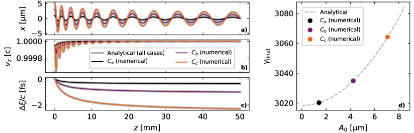
Eqs. (3), (4), (6) and (8) allow for a complete description of the single-particle evolution within the wakefields. In order to test their validity, they have been compared with numerical solutions of Eqs. (1) and (2). Three test cases corresponding to single electrons with different initial transverse offsets are shown in Fig. 1. The electrons in these three cases (, and ) have, respectively, and . They are injected with and propagate 5 cm within a plasma stage with assuming a blowout with , and . The wake velocity is directly determined from the group velocity of a laser driver as if etching effects[52] are neglected, where , assuming a wavelength . The agreement between numerical and analytical solutions is excellent, showing that this single-particle model accurately describes the coupling between longitudinal and transverse dynamics. From these test cases it can also be seen that betatron oscillations with micron-level amplitude can lead to femtosecond-level slippage and energy differences on the percent range.
When considering a particle bunch, these differences in slippage and energy gain between single particles will have an impact on parameters such as the bunch length and energy spread. One immediate consequence will be an increase of the bunch length, which will in turn also lead to increased correlated energy spread if . Another implication, more critical for FEL applications, will be an intra-bunch slice mixing which will lead to a growth of the slice energy spread.
Impact on slice energy spread
In order to obtain an expression for the induced slice energy spread, Eqs. (6) and (8) can be used to calculate the energy difference between two beam particles, and , with the same but different oscillation amplitude, and , which at some time are in the same infinitesimally long beam slice at due to the experienced slippage. If and are constant along the bunch, then for , where is measured at . This allows the particle energy evolution, , to be written in terms of the fields at the current slice. Additionally, if , then can be assumed for the higher order terms in while maintaining the full expression in the leading linear term. This also means that , which, added to the previous considerations, leads to
| (9) |
where . The correlation (if ) within a beam slice arises because, due to slippage, particles with a higher originally come from positions ahead of their current slice. Since , the accelerating fields they have experienced as they slip towards the back are smaller than at their current position, thus leading to a lower net energy gain. Eq. (9) therefore shows that although a positive correlation exists for particles starting at the same slice, as given by Eq. (8), this correlation is actually negative when looking at particles which have ended in the same slice due to slippage. The induced relative slice energy spread due to this effect can be found from the standard deviation of if the mean slice energy is assumed to evolve as , from what it is found that
| (10) |
where , is the standard deviation of for the particles within the slice and is taken at the slice position. For an on-axis Gaussian bunch with zero average transverse momentum ( and ), it can be obtained that , where . The variables , and are, respectively, the beam’s normalized emittance [53], beta function and rms size in both transverse planes, while , with , is the matched beta function [54] defined by the focusing fields within the plasma. For a cylindrically symmetric bunch, i.e, if and , a "mismatch factor" can be defined, where , such that , which leads to the last expression in Eq. (10). For a matched beam () the mismatch factor is , which also corresponds to its minimum value. The impact of betatron slippage on the slice energy spread will therefore be stronger on mismatched beams.
Analyzing Eq. (10) it can be seen that the induced slice energy spread has a fast initial growth until it reaches a maximum when the bunch energy has increased by a factor 9, i.e, when . For higher energies, the slice energy spread slowly decreases proportional to . This behaviour arises from , whose growth rate is initially faster than but gradually slows down due to the reduced slippage at higher energies.
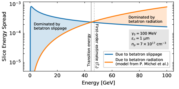
This source of energy spread will act in addition to that due to betatron radiation (BR) [55, 56], which has also been shown to induce a correlation and generate a slice energy spread given by [57] , where and is the classical electron radius. As both effects are induced by the same underlying cause (the betatron motion of particles), it is of interest to compare and determine their relative relevance. This can be done by obtaining the intersection points of Eq. (10) with the BR expression, for which perturbation theory is needed. This method yields that the slippage-induced energy spread will initially dominate over BR if the ratio , where is the coefficient in Eq. (10). When this is the case, a transition into a BR-dominated regime occurs at an energy which, to first order, can be obtained as . An illustration of both regimes can be seen in Fig. 2 for a particular set of parameters. As a general rule, although this will vary from case to case, the energy spread due to slippage will typically dominate over BR up to energies on the order of GeV. This is the energy range in which FELs operate, implying that betatron slippage is the source of slice energy spread that should be minimized for these applications.
An effective way for mitigating the slippage-induced energy spread would be to beam-load the wake such that , thus suppressing the energy spread growth as given by Eq. 10. However, since this condition is difficult to achieve, especially along the whole bunch, other strategies can be derived from this equation. Regarding the accelerating structures, possible strategies include reducing plasma density, since the ratio , or using hollow plasma channels [58], so that . In regards to the accelerated beam, minimizing the emittance, increasing the initial energy and fulfilling matching conditions () would be beneficial, with these two last points being especially relevant for externally injected beams.
Minimizing this slice energy spread is especially important for PBAs based on chirp compensation schemes [32, 33, 35]. This is because although the average experienced by the beam after acceleration might be 0, its value at any point of the accelerator is not, thus giving rise to the development of a slice energy spread which will remain in the de-chirped beam. It is possible, however, that the alternation between positive and negative in these schemes might partially mitigate the correlation from Eq. (9) and thus the slice energy spread, although never remove it completely. As an additional remark, it should also be noted that this correlation between oscillation amplitude and energy caused by betatron slippage has been proposed as a way of performing beam conditioning for FELs [59] by means of a magnetic chicane [60]. Thus, it might also be beneficial in some cases.
Impact on bunch length and total energy spread of ultra-short bunches
In addition to its impact on the slice energy spread, another immediate consequence of the betatron-induced slippage will be a growth of the bunch length. This is especially relevant for ultra-short bunches where the slippage experienced by the particles is comparable to or bigger than the initial bunch length . The contribution of the single-particle slippage to can be directly obtained from the standard deviation of Eq. (6) by assuming an initially monoenergetic bunch with . The bunch lengthening is then found to be
| (11) |
where . The last expression on the right is again obtained for the case of a cylindrically-symmetric Gaussian bunch. The bunch length evolution, when taking into account the impact of slippage, is thus given by for initially Gaussian bunches. When this is the case, this expression therefore establishes a limitation on the minimum bunch length achievable in a PBA. This could have a strong impact on the production of high-energy, sub-femtosecond bunches, because although certain techniques to inject such ultra-short bunches into the plasma wake have been proposed[15, 16, 17, 31], their sub-femtosecond duration could be lost when further accelerating them. Possible ways of mitigating this lengthening can be found by looking at Eq. (11), which yields the same conditions on the beam emittance, matching and initial energy found for Eq. (10). In this case, however, no benefits from beam-loading or reduced plasma density are expected because does not play a role in the lengthening and the ratio does not depend on the plasma density. Another remark that can be extracted from Eq. (11) is that, as expected from Eq. (7), the lengthening has a finite upper limit when given by .
As a consequence of the bunch lengthening, in cases where , the correlated energy spread of the bunch will also increase. This explains previously observed limitations, where convergence to a finite energy spread was found as [45]. This limit on the minimum energy spread as the initial bunch length is reduced can be calculated for an initially monoenergetic beam with from the standard deviation of Eq. (8). This leads to
| (12) |
which, in the same way as Eq. (11), also tends to a finite value as . The last expression on the right corresponds again to the case of a cylindrically-symmetric Gaussian bunch.
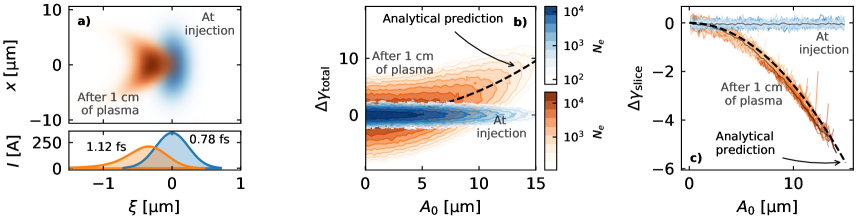
An illustrative example of the phenomena described in this section can be seen in Fig. 3, where an externally injected witness beam is shown at the entry and after 1 cm of plasma, as obtained from an OSIRIS 2D simulation. The induced lengthening as well as the development of a quadratic correlation between energy and oscillation amplitude can be clearly seen. As predicted by Eqs. (8) and (9), this correlation is positive for the overall bunch (Fig. 3b) but negative on the slice level (Fig. 3c).
Validation against 3D PIC simulations
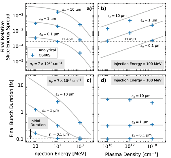
In order to validate and illustrate the significance of the expressions for the slice energy spread and bunch lengthening, a series of 3D simulations with the PIC codes OSIRIS and HiPACE have been performed. The studied cases consisted on a beam-driven plasma stage providing a 1 GeV net energy gain to an externally injected witness beam, as it would be interesting for FEL applications or multi-staged acceleration. In the OSIRIS simulations, the impact of the slippage effects has been tested for different witness beam parameters and plasma densities, and in all cases beam loading effects could always be neglected. On the contrary, the HiPACE simulations where performed to study the possible mitigating effects of beam loading for a fixed set of plasma and beam parameters, where only the total beam charge was varied. Although only beam-driven cases have been simulated, similar results may apply for a laser driver as long as dephasing effects in the mean beam energy can be neglected, as they are not included in Eqs. (10) to (12).
In all simulated cases, a Gaussian driver with an energy of 1 GeV and a spread has been considered. Its dimensions and charge have been defined in terms of the plasma density so that the generated blowout can be scaled with . For the baseline case in which , as used in previous experiments [6], this means a transverse size , a length , a normalized emittance and a peak electron density for a total charge pC and a peak current . The plasma target has a flat-top longitudinal profile and is transversely uniform.
For the studies made with OSIRIS, a Gaussian witness beam is injected on-axis at , where is the driver centre. Different emittance values () as well as injection energies between 10 MeV and 1 GeV have been tested. The transverse size is matched to the focusing fields so that . With regards to the bunch charge and duration, two different sets of parameters have been considered: with 1 pC for the studies on the slice energy spread, as it could be obtained in the SINBAD facility at DESY [61, 62], while a shorter bunch with with 0.1 pC was used for the bunch lengthening studies. This shorter bunch duration was chosen to better highlight the impact of lengthening due to slippage on sub-femtosecond bunches. The peak current in both cases is too low to significantly modify along the bunch, therefore allowing beam loading effects to be neglected. The slice energy spread in all tested beams is dominated by slippage, as and . Also, in order to isolate the plasma stage as the only source of energy spread, a zero longitudinal momentum spread at injection has been considered.
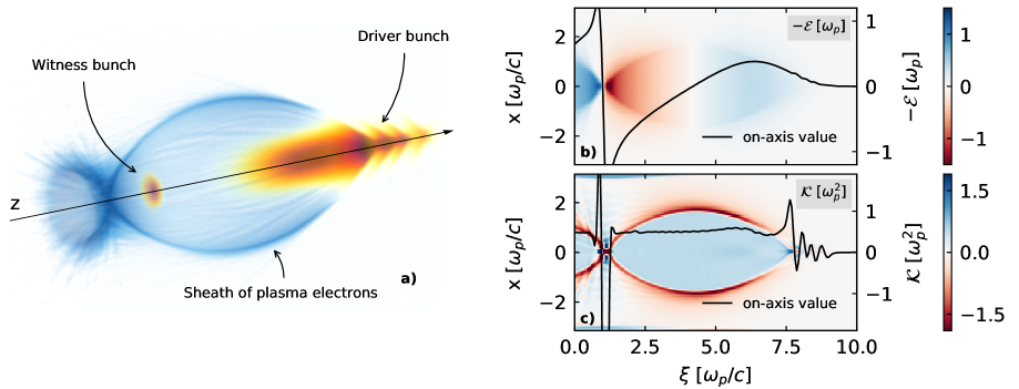
In order to compare the simulation results with the analytical theory, the field values in Eqs. (10) and (11) need to be provided. While these could be estimated from analytical models [49, 63], they were measured directly at from a single simulation with no witness beam, obtaining , and . This allows for a more accurate validation of the model. A view of the plasma wakefields in one of the OSIRIS simulations is shown in Fig. 4. As assumed by the analytical model, a constant within the blowout and a transversely homogeneous with uniform along the witness bunch can be seen.
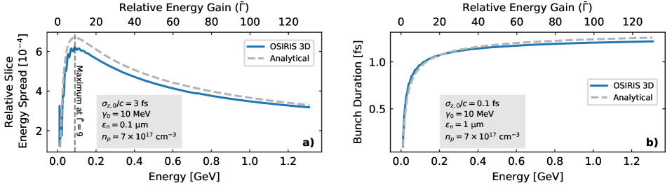
The final simulation results, displayed in Fig. 5, show a strong dependence of the generated slice energy spread on the plasma density and initial beam parameters, reaching values in excess of (or 1%) for certain configurations, way above FEL requirements. Similarly, the increase in bunch length can be on the femtosecond level for typical emittance and energy values, showcasing the difficulty of achieving GeV-class, sub-femtosecond bunches. No variation of the bunch length with the plasma density is observed, as expected from Eq. (11). The analytical model shows excellent agreement with the simulations over several orders of magnitude, with expected discrepancies in some of the higher emittance cases. The differences in Fig. 5(b) arise from the large slippage experienced by particles with higher oscillation amplitude, which causes the transverse distribution of many beam slices to be a truncated Gaussian and thus leads to a smaller energy spread than predicted. The discrepancies in Figs. 5(c) and (d) arise from the longitudinal energy correlation, neglected by Eq. (11), which induces a slight longitudinal bunch compression due to velocity differences between head and tail. In addition to the final slice energy spread and bunch length values, the analytical model also accurately predicts the evolution of these parameters during propagation within the PBA, as shown in Fig. 6. The discrepancies in the energy spread evolution in Fig. 6(a) arise from the initial dephasing between the bunch and plasma wakefield due to the low initial energy (10 MeV), which leads to an experienced accelerating field and, thus, a lower energy spread than predicted by Eq. (10). Furthermore, the initial oscillations on the slice energy spread at the beginning of the simulation correspond to the betatron oscillations of the witness beam, which lead to an oscillation in , as seen previously in Fig. 1(b). When the of the beam particles is minimum (maximum), more (less) slippage occurs and the energy spread growth is faster (slower). This also leads to small oscillations on the bunch length, as seen in Fig. 6(b). The impact of the oscillations on the particle slippage had to be neglected in the theoretical model in order to obtain the analytical expression in Eq. (6). Thus, this effect is not reproduced by the analytical curves shown in Fig. 6.
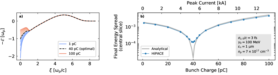
In order to explore the potential of beam loading for mitigating the generated slice energy spread, an additional set of simulations was performed with HiPACE. The same driver parameters as in the OSIRIS simulations and a plasma density of were used. The witness beam parameters were fixed to an initial energy of 100 MeV, and , while its total charge was varied from 1 to 100 pC. The final energy spread of the central bunch slice after a 1 GeV energy gain is shown in Fig. 7 for the different bunch charges. Only the central slice energy spread is displayed in this case because the effect of beam loading on varies along the bunch. The analytical points were calculated from the average value during acceleration of the fields at the center of the bunch.
The results show again good agreement between theory and simulations, and that beam loading can significantly reduce the development of slice energy spread (up to a factor of in this case). For the particular set of parameters under consideration, the energy spread minimum is achieved for a total bunch charge of 40 pC (corresponding to a peak current of kA) and grows again for higher charges because beam loading overcompensates , which becomes positive. Peak currents in this range of parameters have been experimentally demonstrated [9, 10] and, if optimized, could therefore provide an effective way of mitigating the slice energy spread growth. Discrepancies between the analytical curve and the simulations appear, however, around the energy spread minimum. This is because, in theory, the slice energy spread due to slippage could be completely suppressed for an ideally beam-loaded case in which along the whole bunch. This, however, requires an optimized trapezoidal current profile [30] , while the bunch in the simulated case is Gaussian and therefore does not experience a uniform . Thus, even if at the center, a certain energy spread will develop in the central slice due to the slippage of particles originally coming from slices ahead, where . In addition, other effects apart from particle slippage can lead to increased slice energy spread in beam-loaded cases, such as transverse variations of the accelerating fields in the linear and weakly non-linear regimes [66].
Discussion
The presented analytical model and simulation results show that the impact of the betatron-induced slippage could be very significant on beam parameters such as the slice energy spread (up to ) and bunch length (growth on the femtosecond range). These effects should therefore be minimized, and guidelines for their mitigation can be derived from the analytical expressions together with the simulated cases. These show that an effective method of suppressing the slippage-induced slice energy spread growth is the use of beam loading (so that ), while another possible solution would be performing the acceleration in hollow plasma channels (). Otherwise, in order not to rely on these two options, the simulations show that for achieving a slice energy spread , as typically required by FELs, a plasma density , a normalized emittance as well as an initial energy become necessary. The same considerations apply regarding the production of sub-femtosecond bunches, although beam loading or lower plasma densities do not provide any benefit in this case. For applications requiring multiple accelerating stages, such as plasma-based particle colliders, these results imply that the slice energy spread due to slippage would mostly be generated in the first accelerating stage, decreasing at higher energies and eventually being dominated by the emission of betatron radiation.
Methods
3D Particle-in-Cell simulations with OSIRIS
The 3D PIC in simulations corresponding to the results shown in Figs. 4, 5 and 6 where carried out with the OSIRIS code [43] using a standard finite differences field solver [67]. Due to the long propagation distance within the plasma, a co-moving simulation box was considered. The simulation grid on the cases shown in Figs. 5 and 6 consisted on cells and had dimensions of in units of . In the graphs shown in Fig. 4 used for visualizing the fields, the simulation grid was slightly longer, with cells and dimensions of in units of . This was done in order to show the tail of the wakefields, which was otherwise cut off. The time step in all cases was chosen to fulfil the stability criterion [67]. The number of particles per cell was 16 for the beam driver, 1 for the plasma and between 64 and 4096 for the witness beam, depending on the case, in order to have a meaningful total number of particles. The initialization of the electron beams was done using the n_accelerate method in OSIRIS, which progressively increases the longitudinal particle momentum over the specified number of time steps in order to obtain almost self-consistent electromagnetic fields before the beam enters the plasma.
3D Particle-in-Cell simulations with HiPACE
The 3D PIC in simulations corresponding to the results shown in Fig. 7 where carried out with the HiPACE code [44], which is based on the quasi-static approximation. The simulation grid consisted on cells and had dimensions of in units of . A constant time step size of 5 was used. The number of particles per cell was 16 for the beam driver, 3 for the plasma and 512 for the witness beam in order to have a meaningful total number of particles. The initialization of the particle species in HiPACE is performed by computing the self-consistent fields in each time step by means of fast Poisson solvers.
2D Particle-in-Cell simulation with OSIRIS
The data displayed in Fig. 3 showcasing the bunch lengthening and energy spread development comes from a single 2D simulation with OSIRIS of a laser-driven PBA. This simulation considered a plasma density , a Gaussian laser pulse with a peak power of 1.5 PW and a total energy of 25 J, a peak normalized vector potential , a wavelength nm, a spot size and a FWHM duration . The witness bunch has a Gaussian profile based on achievable parameters by the ARES linac at SINBAD [61, 62], featuring a total charge of 0.7 pC, an initial energy of 100 MeV, a duration , a transverse size with and , an emittance and and an energy spread . This simulation was also performed with a standard finite differences field solver [67] considering a co-moving simulation box with cells and dimensions of in units of . The time step was chosen to fulfil the stability criterion [67]. The number of particles per cell was 8 for the plasma and 64 for the witness beam. The initialization method of the witness beam is the same as in the 3D case described above.
Numerical solution of the single-particle equations of motion
As shown in Fig. 1, the equations of motion for a single particle (Eqs. (1) and (2)) were solved numerically to compare against the analytical expressions. These equations were solved with a Runge-Kutta method of order 4 with a time step of 0.01 fs. The fields experienced by the particles take into account dephasing effects assuming a laser driver with nm.
Calculation of the slice energy spread
Due to the limited amount of particles in a PIC simulation, calculating for an infinitesimally short slice as in Eq. (10) is not possible. However, this quantity can be estimated for a finite slice in which the longitudinal energy correlation is removed. The uncorrelated energy distribution can then be obtained as , where is the slope of the correlation. Additionally, since might change along the bunch, the bunches are divided into slices in which is calculated. From there, for the cases shown in Figs. 5 and 6, the slice energy spread of the whole bunch is obtained as the weighted average of the value on each slice. This process is repeated by increasing the number of slices until convergence to a value is reached while still having a significant amount of particles per slice. For the cases to study the effect of beam loading shown in Fig. 7, the value of the slice energy spread only given for the central slice and not as an average.
Data availability
All data displayed in the included figures is available at https://bib-pubdb1.desy.de/record/415560/. Further data supporting this study is available from the corresponding author upon reasonable request.
References
- [1] Tajima, T. & Dawson, J. M. Laser electron accelerator. \JournalTitlePhys. Rev. Lett. 43, 267–270, DOI: 10.1103/PhysRevLett.43.267 (1979).
- [2] Chen, P., Dawson, J. M., Huff, R. W. & Katsouleas, T. Acceleration of electrons by the interaction of a bunched electron beam with a plasma. \JournalTitlePhys. Rev. Lett. 54, 693–696, DOI: 10.1103/PhysRevLett.54.693 (1985).
- [3] Faure, J. et al. Controlled injection and acceleration of electrons in plasma wakefields by colliding laser pulses. \JournalTitleNature (London) 444, 737, DOI: 10.1038/nature05393 (2006).
- [4] Leemans, W. P. et al. Gev electron beams from a centimetre-scale accelerator. \JournalTitleNat. Phys. 2, 696–699 (2006).
- [5] Wang, X. et al. Quasi-monoenergetic laser-plasma acceleration of electrons to 2 gev. \JournalTitleNat. Comm. 4, 1988 (2013).
- [6] Leemans, W. et al. Multi-gev electron beams from capillary-discharge-guided subpetawatt laser pulses in the self-trapping regime. \JournalTitlePhys. Rev. Lett. 113, 245002 (2014).
- [7] Mirzaie, M. et al. Demonstration of self-truncated ionization injection for gev electron beams. \JournalTitleSci. Rep. 5, 14659 (2015).
- [8] Gonsalves, A. J. et al. Petawatt laser guiding and electron beam acceleration to 8 gev in a laser-heated capillary discharge waveguide. \JournalTitlePhys. Rev. Lett. 122, 084801, DOI: 10.1103/PhysRevLett.122.084801 (2019).
- [9] Lundh, O. et al. Few femtosecond, few kiloampere electron bunch produced by a laser–plasma accelerator. \JournalTitleNat. Phys. 7, 219 (2011).
- [10] Couperus, J. et al. Demonstration of a beam loaded nanocoulomb-class laser wakefield accelerator. \JournalTitleNat. Comm. 8, 487 (2017).
- [11] Fritzler, S. et al. Emittance measurements of a laser-wakefield-accelerated electron beam. \JournalTitlePhys. Rev. Lett. 92, 165006 (2004).
- [12] Brunetti, E. et al. Low emittance, high brilliance relativistic electron beams from a laser-plasma accelerator. \JournalTitlePhys. Rev. Lett. 105, 215007 (2010).
- [13] Madey, J. M. Stimulated emission of bremsstrahlung in a periodic magnetic field. \JournalTitleJ. Appl. Phys. 42, 1906–1913 (1971).
- [14] Leemans, W. & Esarey, E. Laser-driven plasma-wave electron accelerators. \JournalTitlePhys. Today 62, 44–49, DOI: 10.1063/1.3099645 (2009).
- [15] Li, F. Y. et al. Dense attosecond electron sheets from laser wakefields using an up-ramp density transition. \JournalTitlePhys. Rev. Lett. 110, 135002 (2013).
- [16] Weikum, M., Li, F., Assmann, R., Sheng, Z. & Jaroszynski, D. Generation of attosecond electron bunches in a laser-plasma accelerator using a plasma density upramp. \JournalTitleNucl. Instr. Meth. Phys. Res., Sect. A 829, 33 – 36, DOI: https://doi.org/10.1016/j.nima.2016.01.003 (2016).
- [17] Tooley, M. P. et al. Towards attosecond high-energy electron bunches: Controlling self-injection in laser-wakefield accelerators through plasma-density modulation. \JournalTitlePhys. Rev. Lett. 119, 044801, DOI: 10.1103/PhysRevLett.119.044801 (2017).
- [18] Zewail, A. H. Femtochemistry: Atomic-scale dynamics of the chemical bond. \JournalTitleJ. Phys. Chem. A 104, 5660–5694, DOI: 10.1021/jp001460h (2000).
- [19] Corde, S. et al. Femtosecond x rays from laser plasma accelerators. \JournalTitleRev. Mod. Phys 85, 1 (2013).
- [20] Migliorati, M. et al. Intrinsic normalized emittance growth in laser-driven electron accelerators. \JournalTitlePhys. Rev. ST Accel. Beams 16, 011302, DOI: 10.1103/PhysRevSTAB.16.011302 (2013).
- [21] Dornmair, I., Floettmann, K. & Maier, A. R. Emittance conservation by tailored focusing profiles in a plasma accelerator. \JournalTitlePhys. Rev. ST Accel. Beams 18, 041302, DOI: 10.1103/PhysRevSTAB.18.041302 (2015).
- [22] van Tilborg, J. et al. Active plasma lensing for relativistic laser-plasma-accelerated electron beams. \JournalTitlePhys. Rev. Lett. 115, 184802, DOI: 10.1103/PhysRevLett.115.184802 (2015).
- [23] Esarey, E., Hubbard, R. F., Leemans, W. P., Ting, A. & Sprangle, P. Electron injection into plasma wakefields by colliding laser pulses. \JournalTitlePhys. Rev. Lett. 79, 2682–2685, DOI: 10.1103/PhysRevLett.79.2682 (1997).
- [24] Oz, E. et al. Ionization-induced electron trapping in ultrarelativistic plasma wakes. \JournalTitlePhys. Rev. Lett. 98, 084801, DOI: 10.1103/PhysRevLett.98.084801 (2007).
- [25] Schmid, K. et al. Density-transition based electron injector for laser driven wakefield accelerators. \JournalTitlePhys. Rev. ST Accel. Beams 13, 091301, DOI: 10.1103/PhysRevSTAB.13.091301 (2010).
- [26] Martinez de la Ossa, A., Grebenyuk, J., Mehrling, T., Schaper, L. & Osterhoff, J. High-quality electron beams from beam-driven plasma accelerators by wakefield-induced ionization injection. \JournalTitlePhys. Rev. Lett. 111, 245003, DOI: 10.1103/PhysRevLett.111.245003 (2013).
- [27] Hidding, B. et al. Ultracold electron bunch generation via plasma photocathode emission and acceleration in a beam-driven plasma blowout. \JournalTitlePhys. Rev. Lett. 108, 035001, DOI: 10.1103/PhysRevLett.108.035001 (2012).
- [28] Katsouleas, T. C., Wilks, S., Chen, P., Dawson, J. M. & Su, J. J. Beam Loading in Plasma Accelerators. \JournalTitlePart. Accel. 22, 81–99 (1987).
- [29] Lotov, K. V. Efficient operating mode of the plasma wakefield accelerator. \JournalTitlePhysics of Plasmas 12, 053105, DOI: 10.1063/1.1889444 (2005).
- [30] Tzoufras, M. et al. Beam loading in the nonlinear regime of plasma-based acceleration. \JournalTitlePhys. Rev. Lett. 101, 145002 (2008).
- [31] Martinez de la Ossa, A., Mehrling, T. J., Schaper, L., Streeter, M. J. V. & Osterhoff, J. Wakefield-induced ionization injection in beam-driven plasma accelerators. \JournalTitlePhysics of Plasmas 22, 093107, DOI: 10.1063/1.4929921 (2015). https://doi.org/10.1063/1.4929921.
- [32] Manahan, G. et al. Single-stage plasma-based correlated energy spread compensation for ultrahigh 6d brightness electron beams. \JournalTitleNat. Comm. 8 (2017).
- [33] Brinkmann, R. et al. Chirp mitigation of plasma-accelerated beams by a modulated plasma density. \JournalTitlePhys. Rev. Lett. 118, 214801 (2017).
- [34] Döpp, A. et al. Energy-chirp compensation in a laser wakefield accelerator. \JournalTitlePhys. Rev. Lett. 121, 074802, DOI: 10.1103/PhysRevLett.121.074802 (2018).
- [35] Ferran Pousa, A., Martinez de la Ossa, A., Brinkmann, R. & Assmann, R. W. Compact multistage plasma-based accelerator design for correlated energy spread compensation. \JournalTitlePhys. Rev. Lett. 123, 054801, DOI: 10.1103/PhysRevLett.123.054801 (2019).
- [36] Bane, K. & Stupakov, G. Corrugated pipe as a beam dechirper. \JournalTitleNucl. Instr. Meth. Phys. Res., Sect. A 690, 106 – 110 (2012).
- [37] Antipov, S. et al. Experimental demonstration of energy-chirp compensation by a tunable dielectric-based structure. \JournalTitlePhys. Rev. Lett. 112, 114801, DOI: 10.1103/PhysRevLett.112.114801 (2014).
- [38] D’Arcy, R. et al. Tunable plasma-based energy dechirper. \JournalTitlePhys. Rev. Lett. 122, 034801, DOI: 10.1103/PhysRevLett.122.034801 (2019).
- [39] Shpakov, V. et al. Longitudinal phase-space manipulation with beam-driven plasma wakefields. \JournalTitlePhys. Rev. Lett. 122, 114801 (2019).
- [40] Wu, Y. P. et al. Phase space dynamics of a plasma wakefield dechirper for energy spread reduction. \JournalTitlePhys. Rev. Lett. 122, 204804, DOI: 10.1103/PhysRevLett.122.204804 (2019).
- [41] Reitsma, A. & Jaroszynski, D. Coupling of longitudinal and transverse motion of accelerated electrons in laser wakefield acceleration. \JournalTitleLaser Part. Beams 22, 407–413 (2004).
- [42] Xu, X. et al. Phase-space dynamics of ionization injection in plasma-based accelerators. \JournalTitlePhys. Rev. Lett. 112, 035003 (2014).
- [43] Fonseca, R. A. et al. Osiris: A three-dimensional, fully relativistic particle in cell code for modeling plasma based accelerators. In Sloot, P. M. A., Hoekstra, A. G., Tan, C. J. K. & Dongarra, J. J. (eds.) The 2002 International Conference on Computational Science (Springer, Amsterdam, 2002).
- [44] Mehrling, T., Benedetti, C., Schroeder, C. B. & Osterhoff, J. HiPACE: a quasi-static particle-in-cell code. \JournalTitlePlasma Physics and Controlled Fusion 56, 084012, DOI: 10.1088/0741-3335/56/8/084012 (2014).
- [45] Grebenyuk, J., Assmann, R., Dorda, U. & Marchetti, B. Laser-driven Acceleration with External Injection at SINBAD. In Petit-Jean-Genaz, C., Arduini, G., Michel, P. & Schaa, V. R. (eds.) 5th International Particle Accelerator Conference (JACoW, Dresden, 2014).
- [46] Gorbunov, L. & Kirsanov, V. Excitation of plasma waves by an electromagnetic wave packet. \JournalTitleSov. Phys. JETP 66, 40 (1987).
- [47] Sprangle, P., Joyce, G., Esarey, E. & Ting, A. Laser wakefield acceleration and relativistic optical guiding. In Roberson, C. W. & Driscoll, C. F. (eds.) Non-Neutral Plasma Physics (AIP, Washington, 1988).
- [48] Lotov, K. Blowout regimes of plasma wakefield acceleration. \JournalTitlePhys. Rev. E 69, 046405 (2004).
- [49] Lu, W., Huang, C., Zhou, M., Mori, W. B. & Katsouleas, T. Nonlinear theory for relativistic plasma wakefields in the blowout regime. \JournalTitlePhys. Rev. Lett. 96, 165002 (2006).
- [50] Schroeder, C. B., Benedetti, C., Esarey, E. & Leemans, W. P. Nonlinear pulse propagation and phase velocity of laser-driven plasma waves. \JournalTitlePhys. Rev. Lett. 106, 135002 (2011).
- [51] Kostyukov, I., Pukhov, A. & Kiselev, S. Phenomenological theory of laser-plasma interaction in “bubble” regime. \JournalTitlePhys. Plasmas 11, 5256–5264 (2004).
- [52] Lu, W. et al. Generating multi-gev electron bunches using single stage laser wakefield acceleration in a 3d nonlinear regime. \JournalTitlePhys. Rev. ST Accel. Beams 10, 061301, DOI: 10.1103/PhysRevSTAB.10.061301 (2007).
- [53] Floettmann, K. Some basic features of the beam emittance. \JournalTitlePhys. Rev. ST Accel. Beams 6, 034202 (2003).
- [54] Assmann, R. & Yokoya, K. Transverse beam dynamics in plasma-based linacs. \JournalTitleNucl. Instr. Meth. Phys. Res., Sect. A 410, 544–548 (1998).
- [55] Wang, S. et al. X-ray emission from betatron motion in a plasma wiggler. \JournalTitlePhys. Rev. Lett. 88, 135004 (2002).
- [56] Esarey, E., Shadwick, B. A., Catravas, P. & Leemans, W. P. Synchrotron radiation from electron beams in plasma-focusing channels. \JournalTitlePhys. Rev. E 65, 056505 (2002).
- [57] Michel, P., Schroeder, C. B., Shadwick, B. A., Esarey, E. & Leemans, W. P. Radiative damping and electron beam dynamics in plasma-based accelerators. \JournalTitlePhys. Rev. E 74, 026501 (2006).
- [58] Chiou, T. et al. Laser wake-field acceleration and optical guiding in a hollow plasma channel. \JournalTitlePhys. Plasmas 2, 310–318 (1995).
- [59] Sessler, A. M., Whittum, D. H. & Yu, L.-H. Radio-frequency beam conditioner for fast-wave free-electron generators of coherent radiation. \JournalTitlePhys. Rev. Lett. 68, 309 (1992).
- [60] Pennt, G., Sessler, A. M. & Wurtelel, J. A plasma channel beam conditioner for a free electron laser. In Petit-Jean-Genaz, C. (ed.) 22nd Particle Accelerator Conference (IEEE, Piscataway, 2007).
- [61] Assmann, R. et al. SINBAD - A Proposal for a Dedicated Accelerator Research Facility at DESY. In Petit-Jean-Genaz, C., Arduini, G., Michel, P. & Schaa, V. R. (eds.) 5th International Particle Accelerator Conference (JACOW, Dresden, 2014).
- [62] Zhu, J., Assmann, R. W., Dohlus, M., Dorda, U. & Marchetti, B. Sub-fs electron bunch generation with sub-10-fs bunch arrival-time jitter via bunch slicing in a magnetic chicane. \JournalTitlePhys. Rev. Accel. Beams 19, 054401 (2016).
- [63] Yi, S., Khudik, V., Siemon, C. & Shvets, G. Analytic model of electromagnetic fields around a plasma bubble in the blow-out regime. \JournalTitlePhys. Plasmas 20, 013108 (2013).
- [64] Ferran Pousa, A., Assmann, R. & Martinez de la Ossa, A. VisualPIC: A New Data Visualizer and Post-Processor for Particle-in-Cell Codes. In 8th International Particle Accelerator Conference (IPAC 2017), DOI: 10.18429/JACoW-IPAC2017-TUPIK007 (2017).
- [65] Schreiber, S. & Faatz, B. The free-electron laser flash. \JournalTitleHigh Power Laser Sci. Eng. 3 (2015).
- [66] Li, X., Nghiem, P. A. P. & Mosnier, A. Toward low energy spread in plasma accelerators in quasilinear regime. \JournalTitlePhys. Rev. Accel. Beams 21, 111301, DOI: 10.1103/PhysRevAccelBeams.21.111301 (2018).
- [67] Yee, K. Numerical solution of initial boundary value problems involving maxwell’s equations in isotropic media. \JournalTitleIEEE Transactions on Antennas and Propagation 14, 302–307, DOI: 10.1109/TAP.1966.1138693 (1966).
Acknowledgements
This project has received funding from the European Union’s Horizon 2020 research and innovation programme under grant agreement No. 653782. We thank the OSIRIS consortium (IST/UCLA) for access to the OSIRIS code and acknowledge the computing time grant by the Jülich Supercomputing Center on JUQUEEN under Project No. HHH23 as well as the use of the Maxwell Cluster at DESY. We would also like to thank Dr. Reinhard Brinkmann, Dr. Klaus Floettmann and Thomas Heinemann for their relevant input and discussions.
Author contributions statement
A.F.P. developed the analytical model, performed the simulations, prepared the figures and wrote the manuscript. A.M.O. contributed to the development of the model, provided PIC simulations support and participated in the writing of the manuscript. R.W.A. originally proposed studying the impact of the phenomena here described, provided input on the accelerator physics involved and contributed to the writing of the manuscript.
Additional information
Competing interests
The authors declare no competing interests.