2North Carolina State University, Raleigh, NC 27695, USA
3Los Alamos National Laboratory, Los Alamos, New Mexico 87545, USA
4ETH Zürich, CH-8093 Zürich, Switzerland
5Inst. of Nuclear Chemistry, Johannes Gutenberg University of Mainz, D-55128 Mainz, Germany
Solid deuterium surface degradation at ultracold neutron sources
Abstract
Solid deuterium (sD2) is used as an efficient converter to produce ultracold neutrons (UCN). It is known that the sD2 must be sufficiently cold, of high purity and mostly in its ortho-state in order to guarantee long lifetimes of UCN in the solid from which they are extracted into vacuum. Also the UCN transparency of the bulk sD2 material must be high because crystal inhomogeneities limit the mean free path for elastic scattering and reduce the extraction efficiency. Observations at the UCN sources at Paul Scherrer Institute and at Los Alamos National Laboratory consistently show a decrease of the UCN yield with time of operation after initial preparation or later treatment (“conditioning”) of the sD2. We show that, in addition to the quality of the bulk sD2, the quality of its surface is essential. Our observations and simulations support the view that the surface is deteriorating due to a build-up of D2 frost-layers under pulsed operation which leads to strong albedo reflections of UCN and subsequent loss. We report results of UCN yield measurements, temperature and pressure behavior of deuterium during source operation and conditioning, and UCN transport simulations. This, together with optical observations of sD2 frost formation on initially transparent sD2 in offline studies with pulsed heat input at the North Carolina State University UCN source results in a consistent description of the UCN yield decrease.
pacs:
28.20.-v and 29.25.Dz and 14.20.Dh1 Introduction
Deuterium is one of the best neutron moderator materials because of its small mass and small nuclear absorption cross section. In the liquid phase, it is the favorite material for cold neutron sources at continuous research reactors and accelerator-based spallation sources. As solid deuterium (sD2), it is an exceptional material for optimized production of very low energy, so-called “ultracold neutrons (UCN)”, with energies below about 350 neV Golub1991 . These UCN can be trapped for several hundreds of seconds, limited ultimately by the neutron beta-decay lifetime, allowing for long observation and manipulation times. This provides a significant gain for many experiments in fundamental, low-energy particle physics Abele2008 ; Dubbers2011 .
The quality of a neutron source in terms of the neutron intensity delivered and available to experiments depends on many parameters, including the neutron production process, the moderator setup, and the specific geometries and materials used. The potential of sD2 for UCN production in a continuous source has been first demonstrated experimentally in Gatchina Altarev1980b and put on solid theoretical grounds shortly thereafter Golub1983 ; Yu1986 . In the 1990s, when the saturation of UCN intensities at available sources (mainly the Steyerl turbine at the ILL in Grenoble Steyerl1986 ) became a limiting factor, research into improved UCN production mechanisms was intensified, concentrating on developing so-called super-thermal sources Golub1977 either using superfluid helium or sD2.
For sD2, pioneering work continued at the Petersburg Nuclear Physics Institute (PNPI), Gatchina Serebrov1994 ; Serebrov1995b ; Serebrov2000 ; Serebrov2001b , and triggered renewed interest in pulsed sD2 sources, see Pokotilovski1995 for suggestion of a lay-out. Conceptually, a UCN source would produce neutrons from fission or spallation, have separate or combined thermal and cold moderation, and produce UCN inside a sD2 converter that could also serve as the cold moderator. The UCN produced inside the sD2 must leave the converter into vacuum within their lifetime that is limited by absorption and upscattering losses. High UCN densities in vacuum can be obtained by guiding the UCN from the converter to a separate, low-loss volume that can be closed synchronized to pulsed production.
The first sD2-based UCN source driven by a pulsed proton beam, which was realized in Los Alamos Morris2002 ; Saunders2004 has yielded insights about relevant UCN loss mechanisms inside sD2. Thermal and para-D2 upscattering Morris2002 ; Liu2000 , were found to limit the lifetime of UCN inside the sD2 and affect efficient UCN extraction from the converter. In a series of experiments at the Paul Scherrer Insitute (PSI) in Villigen and at the Institute Laue-Langevin (ILL), Grenoble, the UCN production process from cold neutrons (CN) in sD2 has been quantitatively studied integrated over a CN spectrum Atchison2005 , CN velocity dependent Atchison2007 and via CN measurements of the sD2 density of states Frei2010b . The influence of the crystalline properties of the sD2, i.e. the effect of UCN elastic scattering on inhomogeneities, its variations with quality of the bulk material, and consequently the large changes in UCN residence times inside and extraction efficiencies out of sD2 into vacuum have been studied in Atchison2005b ; Atchison2011 and further worked out, e.g. in Pokotilovski2012 .
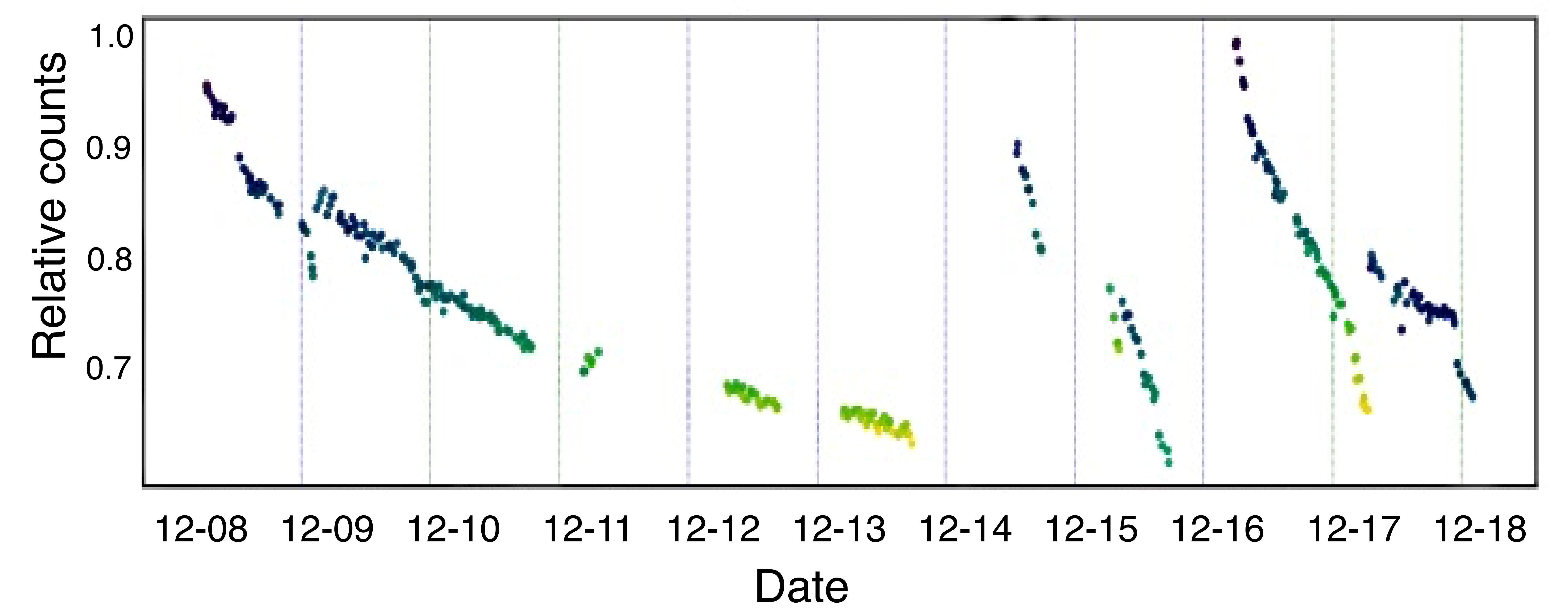

Meanwhile, three facilities are utilizing pulsed UCN production from sD2. These are spallation sources at LANL Saunders2004 ; LANL2000 ; LANL2013 ; Ito2018 and PSI Anghel2009 ; Lauss2011 ; Lauss2012 ; Lauss2014 ; Becker2015 ; Bison2017 , and at the Mainz TRIGA reactor source Karch2014 ; Kahlenberg2017 . Although basic processes of UCN production and extraction from the source are understood, there is a puzzling observation of a dynamic process during operation of the pulsed UCN sources which is displayed in Fig. 1. The UCN yield in the sources at LANL and at PSI declines with the operating time of the sD2, apparently correlated to the delivered proton beam charge, at a rate of 5-20% per day as shown in Fig. 1111A decline was initially also observed at the Mainz TRIGA UCN facility Karch2014 . This decrease appears to either not be present or to be masked by other effects in newer measurements Kahlenberg2017 .. The initial UCN yield can be recovered as shown in the sequences of Fig. 1. At LANL, the routine procedure is to melt and re-freeze the entire sD2 volume of 1 dm3 about once a day. At PSI, the sD2 volume is about 30 dm3. Melting and refreezing is a long process for the PSI source and does not immediately improve the UCN yield. However, a procedure (“conditioning”) of treating the sD2 for about 1.5 hours, leads to a full recovery of the UCN yield. Conditioning includes two main steps, reduction of the D2 cooling and powering the heaters mounted to the lid of the sD2 vessel. Neither of these steps alone is sufficient to recover the UCN yield.
In this paper we report measurements of the UCN intensity decrease observed at accelerator-driven sD2 based UCN sources under continuous operation. Observations at the PSI UCN source, discussed in detail in the next section, suggest that the deterioration of the UCN yield is due to surface effects. All indications point to the growth of frost layers on the top surface which subsequently impede the transmission of UCN. These findings are supported by the visual offline inspection of sD2 surfaces under a heat pulse operation at the North Caroline State University (NSCU) UCN facility Korobkina2007 . The UCN transport simulation in Sec. 3.2 strongly supports this interpretation of the observed UCN intensity decrease.
1.1 Properties of cryogenic deuterium
In order to make the following discussions concerning solid D2 properties most accessible to the reader, we here recall some properties of deuterium, in particular of cryogenic D2. For further reading, we refer the reader to the excellent, comprehensive book by Souers on the properties of the hydrogen isotopes Souers1986 from which much of the background information and many of the values in this subsection are quoted.
To guarantee good UCN performance, the UCN converter should consist of pure solid ortho-D2 with as little as possible para-D2 and H contamination Morris2002 . While UCN losses due to upscattering and absorption are an important aspect of it, another one is the transparency of the sD2 for UCN. Under all reasonable conditions for UCN sources, ortho-D2 solidifies in hexagonal closed-packed (hcp) lattices. It is possible to grow optically transparent crystals from high purity ortho-D2, however, the para-D2 and H contaminations behave as crystal defects and make obtaining “nice” solids much harder. It is however known, that elastic UCN scattering on crystal defects can hinder UCN extraction from the solid into vacuum and thereby deteriorate UCN source performance Atchison2005b . Therefore, starting with D2 of high isotopic purity (99.8% or, even better, 99.95%) is mandatory as is the efficient conversion of para- to ortho-D2. At room temperature, the equilibrium spin population of the D2 molecules corresponds to the high-temperature limit of one third para-D2 (there are in total three para-D2, nuclear spin and six ortho-D2, sub-states). At low temperatures, the equilibrium goes to the lower energy ortho states, however, the natural transition rates are extremely slow. Therefore, UCN sources use catalyzed conversion to ortho-D2, most commonly in the liquid state near the triple point on a paramagnetic substance, see Liu2000 ; Bodek2004 . This guarantees high mobility of the D2 molecules to reach the surface of the catalyst and as low temperature as possible.
At the triple point, the D2 temperature is 18.7 K and its vapor pressure 171 hPa. The equilibrium ortho concentration at the triple point is 98.5%. This can be further enhanced as the UCN sources operate at lower temperatures. While the natural conversion remains slow, the rates can be considerably enhanced under irradiation Collins1991 .
An additional benefit of a high ortho-D2 concentration is the high thermal conductivity of the solid, up to more than 30 W/m/K at 5 K but dropping quickly to around 1 W/m/K at 12 K. The heat capacity is strongly increasing with increasing temperature, starting from 0.5 J/mol/K at 4 K it is about 1 J/mol/K at 8 K and reaches 4 J/mol/K at 12 K.
In the UCN sources at LANL and at PSI, sD2 is routinely frozen from the liquid phase, cooling more or less slowly through the triple point. The D2 molar volume changes from 23.17 to 20.44 cm3/mol above and below the triple point, respectively, when going from liquid to solid. The contraction of the solid D2 continues when further cooling down, the molar volumes are 20.21, 19.97, 19.93 cm3/mol at 16, 10, 4 K, respectively. It is known that thermal stress induced crystal defects can considerably increase the UCN elastic scattering in the solid. These can occur when cooling down to operational conditions but also in thermal cycles when operating the UCN source in a pulsed mode Atchison2005b .
The saturated vapor pressure of the solid depends strongly on temperature with pressures of 3390, 98, 6.5, 0.12, and 0.0002 Pa at 16, 12, 10, 8, and 6 K, respectively. In principle it is possible to measure the equilibrium temperature of the sD2 surface by measuring the D2 vapor pressure. In the pressure data of the PSI UCN source shown below, the situation is more complicated. The pressure gauges are limited and cannot measure pressures below a fraction of a Pa. Also, one must deal with transient pressures during pulsed operation measured with gauges at the end of roughly 10 m long gas pipes away from the sD2. Additionally, a small contamination of the D2 gas with 4He prevents the straight forward interpretation, however, allows for a more complicated analysis using the 4He as a gas thermometer. This analysis is much more involved and beyond the scope of the present paper.
2 Experimental observations
2.1 Measurements at the PSI facility
The UCN source at PSI is based on spallation of lead using the full 1.3 MW, 590 MeV proton beam cyclotron2010 directed onto the UCN spallation target Wohlmuther2006 for up to 8 s. Spallation neutrons are subsequently thermalized in heavy water, a process that is well understood and modeled in a full MCNP-X simulation Becker2015 containing all important geometry details of the target and moderator area of the UCN source. Thermal neutrons can then enter the moderator vessel cooled to 5 K containing about 30 dm3 of solid ortho-deuterium, where they are moderated to cold neutrons. Finally, they may become ultracold via phonon down-scattering in the sD2 Golub1991 ; Atchison2007 ; Atchison2011 ; LANL2000 ; Kirch2010 ; Atchison2009b ; Serebrov1997 ; Young2014 . During the proton pulse UCN are produced and then stored in a 2m3 large storage vessel, providing UCN to three beamlines. In recent years a detailed model of the UCN transport in the PSI UCN source has been developed. Typical pulse repetition intervals are 300 s or 500 s. To obtain information on the source performance, UCN can be counted at a beamport, integrating over one pulse interval; the corresponding counts are shown in Fig. 1-bottom for a one week period. The intensity decrease with time is obvious. Full restoration of the UCN intensity is achieved in a conditioning procedure (see below).
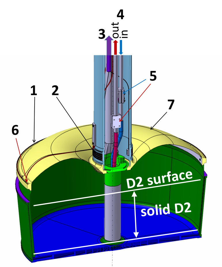
A cut view of the moderator vessel (=48 cm) made mainly from AlMg3 is shown in Fig. 2 with indicated approximate height of the sD2 of about 15 cm maximum level. The vessel is cooled by supercritical helium at 4.5 K which enters through a central pipe and flows radially through the bottom plate and up the side walls and back. The cooling pipes are indicated in Fig. 2. The vessel is equipped with temperature sensors for the He lines (Cernox) and on the vessel lid (thermocouple Type E - sensor CT302). The gas pressure above the deuterium is measured about 10 m away at room temperature with a gas-type independent capacitance diaphragm gauge (CP006) connected via a DN25 tube.
In order to assess the impact on the sD2 of beam pulsing, we show in Fig. 3 the pressure above the sD2 and the temperature at the outside rim of the vessel lid for a period of continuous pulse operation. Both sensors show a steep increase in pressure and temperature during the proton beam pulse and a relaxation afterwards towards the equilibrium value.


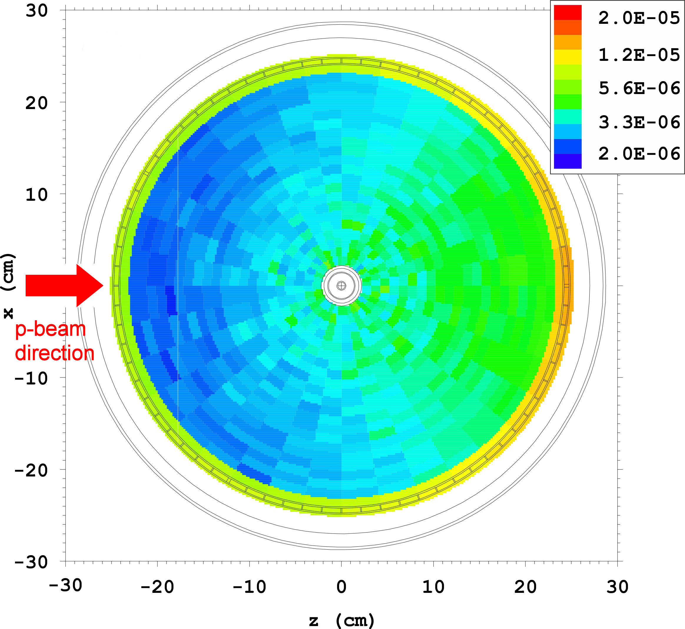
MCNP-X is also used to simulate the energy deposition in the relevant source materials Talanov2017 . Fig. 4 shows the energy density (MeV/cm3) per proton on target deposited in the top 1 cm of the sD2 bulk. The total of -ray and neutron heating for an 8 s pulse of 2.2 mA results in an energy deposition of about 0.1 J/cm3 in the sD2 in that layer. The asymmetry is caused by the asymmetry in the neutron flux reflecting the proton beam direction (origination at -z). Higher power deposition occurs in the aluminum material of the vessel, which shows up as the colored outside ring.
The UCN intensity at PSI, plotted in
Fig. 1-bottom,
shows that periods of deterioration
over 1 day are followed by a short period without
beam, where conditioning is done.
This results in a reliable full recovery of the output intensity.
The conditioning procedure consists of two components:
Part 1: Reducing
the standard
He coolant flow to a minimum value.
The flow is not completely stopped in order to prevent
instabilities in the cooling circuit when returning to regular cooling conditions.
Part 2: Switching on the lid heaters located on the moderator vessel
as shown in Fig. 2.
Inner and outer lid heaters are turned on to a
power of 7.5 W each.
These steps together cause a temperature increase of the D2 surface region to 10-12 K as derived from the vapor pressure. After about 60 min the cooling power is gradually restored over 30 minutes to regular conditions. Finally both heaters are switched off. It is important to note that only the combination of cooling flow reduction and lid heating ensures the full recovery of the UCN yield.
Figure 5 shows the evolution of the D2 vapor pressure (sensor CP006) during two subsequent conditioning procedures. In procedure 1, following a UCN source operation period with 1112 pulses, the vapor pressure rises to a maximum of around 53 Pa and then, without any change to the cooling conditions, drops to around 33 Pa, similar to the maximum pressure level observed in the second procedure which was performed subsequently. Between the 2 procedures two 2 s long proton pulses were used to check that the UCN yield was fully regained. The second conditioning resulted in no further gain of the UCN yield. During regular source operation the total time used for a conditioning period can be as short as 90 min with full UCN yield recovery.
During regular UCN source operations (see Fig. 1, bottom, single conditioning procedures were performed many times over several months and the same pressure behavior was observed.
We interpret these pressure curves as follows: During every proton pulse some D2 sublimates, and a small amount of it contributes to the buildup of a layer that is poorly attached to the sD2 surface, a frost/snow-like layer. After operating the UCN source for an extended period with several tens to hundreds of proton pulses a conditioning procedure is performed. During this conditioning the D2 surface warms up and sublimation of D2 occurs first from the frost layer.

Sublimation of this layer causes the steep pressure increase up to a maximum value, e.g., around 53 Pa as in Fig. 5.
After a certain time, most of the badly-cooled D2 frost is sublimated and resublimated (presumably as better quality D2 ice) at colder surfaces causing the pressure to decrease despite the reduced cooling. A lower pressure level is then established towards the end of the first conditioning, which corresponds to the maximum level obtained in the subsequent second conditioning of Fig. 5. The two, short 2 s, long proton beam pulses applied for UCN gain monitoring between the conditioning procedures do not produce appreciably new frost.
The build up of frost layers is proportional to the accumulated (total) number of pulses. Fig. 6 displays data from standard conditioning procedures performed in an operating period in fall 2017. One observes a clear correlation between the maximum vapor pressure in the conditioning procedure – corresponding to more material evaporated – and the number of beam pulses, i.e. the total proton charge since the previous conditioning. The growing layer thickness results in a continuous reduction of the UCN yield as observed and supported by UCN simulations, see Sec. 3.2 below.

Measurements of the UCN intensity over time were performed at beamports West-1 and West-2 at the PSI UCN facility detailed in Fig.1 of Ref. Lauss2012 , where a Cascade UCN detector222C-DT, Hans-Bunte Str. 8-10, Heidelberg, Germany was installed directly at the beamport. The West-1 beamport is located about 1.13 m and the West-2 beamport 3.23 m above the sD2 surface. This results in a relative shift of the UCN energy spectra at the two beamports. UCN which can reach the higher beamport have a minimum energy of 320 neV outside the sD2 surface, while UCN at West-1 have a minimum energy of 113 neV, similar to the kinetic energy boost by the sD2 potential Daum2008 ; Altarev2008 . Both beamlines are equipped with identically produced UCN guides made from glass tubes with inside coating of nickel-molybdenum Blau2016 .
In 2016 and 2017, the UCN yield decrease during operation was observed over months of continuous UCN source operation, i.e. when pulses typically of 8 s length and with 300 s repetition interval were delivered continuously. These were the operating conditions for the nEDM experiment at PSI Baker2011 ; Pendlebury2015 . No UCN yield change was observed when the sD2 was left undisturbed, even after several days without pulses.


The long period of decrease, observed in Fig. 1, corresponds to three days with continuous pulse operation without conditioning. Figure 7 compares the UCN intensities for West-1 and West-2 during this period. Correlated fluctuations are due to variations in proton beam current. A clear difference is observed at the two beamports, with the rate decline being more pronounced in West-1. Figure 8 shows the ratio of relative counts observed at the two beamports (West-1/West-2). After the conditioning procedure, the ratio stays constant for a few hours but then starts to decrease continuously. This decrease can be attributed to the formation of a growing frost layer on top of the D2 surface. The UCN rate at the lower beamport decreases faster than at the higher beamport since only UCN passing the surface with higher kinetic energies are able to reach the top beamport, and these are less affected by a possibly energy dependent transmission loss in the frost layer. The initial constant behavior is the subject of ongoing research.
2.2 UCN measurements at LANL UCN source
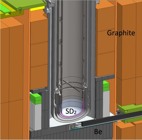
Solid deuterium UCN source development at LANL began with a series of prototypes LANL2000 , followed by commissioning the first “production” source in 2005, which ran until 2016 LANL2013 when a major upgrade to the source was implemented Ito2018 . The upgraded source is currently in operation. The later prototypes and subsequent sources all have very similar geometries, consisting of a sD2 source situated at the bottom of a roughly 1 m vertical guide, which is coupled via an “elbow” at the top to horizontal guides which exit the biological shielding. A “flapper” valve located immediately above the sD2 opens during the proton pulse and then shuts rapidly to prevent UCN loaded into the guide system from re-entering the sD2 source between pulses. The most recent geometry of the source is shown in Fig. 9. The UCN yield decline is observed in both production sources.
As was mentioned in the introduction, the sD2 volume is 1 dm3, which can be easily melted and re-frozen to recover UCN intensity. The LANL source repair procedure is different from the PSI procedure because it involves a full melt and re-freeze of the bulk sD2, resulting in changes not only to the surface, but also to the bulk properties of the sD2. Note that while the source operators have attempted to develop a reproducible procedure, variations are unavoidable. As will be explained in the simulation section, the total frost effect depends on the bulk properties, so the rate of UCN yield decline varies more for the LANL source than the PSI source.
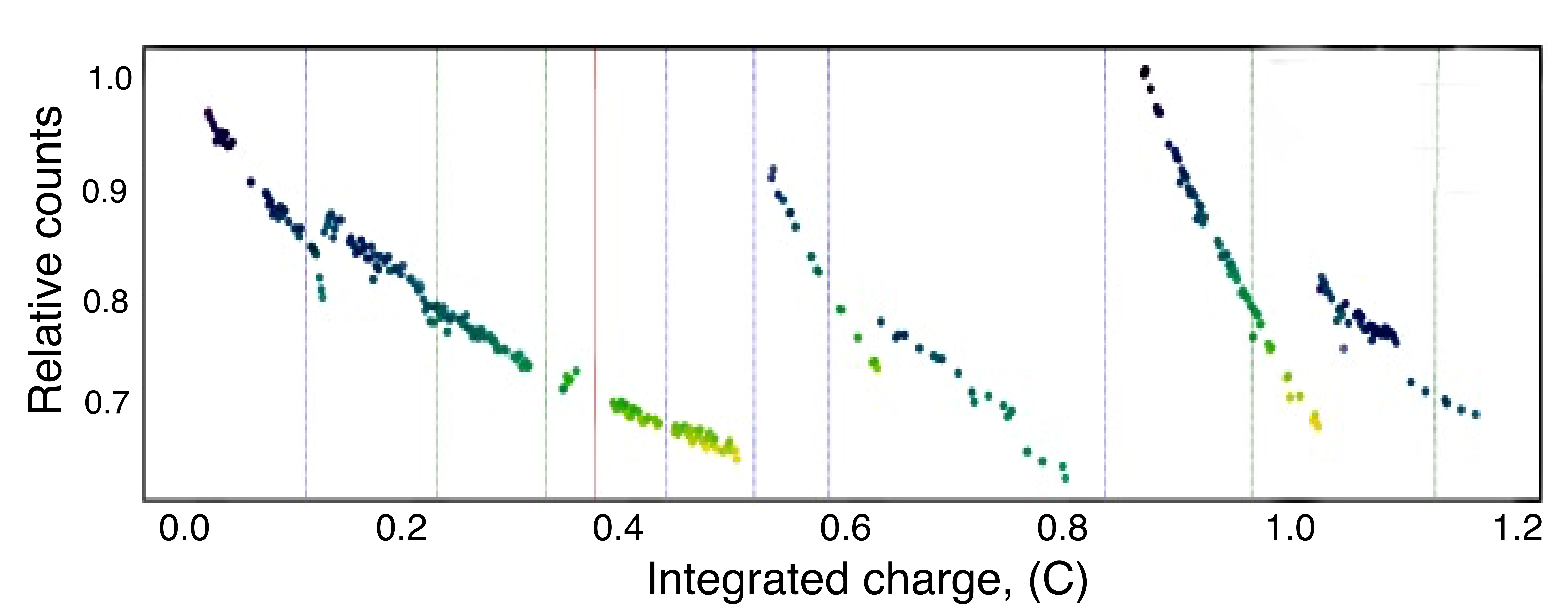
The LANL UCN source has two sets of detectors monitoring the UCN rate, located at different elevations, and therefore, probing different parts of the UCN spectrum. The first location is near the main gate valve just outside the biological shield, which separates the UCN source from the neutron guide network, connected to different experiments LANL2013 . There are two detectors at this location, called upstream normalization detectors, probing the total UCN spectrum coming from the source. The count rate of one of these monitors is shown in Fig. 1 versus date and in Fig. 10 versus integrated beam charge. The comparison shows that there is no UCN yield attenuation without the beam running. The second set of detectors is part of the UCNTau magnetic storage experiment Young2014 ; Pattie2017 . This set, called the elevated normalization detectors, has the highest detector elevated about 1 m above the main beam height.
The ratio of UCN count rates of the upstream to the highest elevated monitor counter versus time is shown in Fig. 11. Compared with a monitor detector proportional to the total yield (Fig. 1), one clearly can see the correlation between the spectrum-sensitive ratio and the overall yield from the source. The decrease of the ratio is due to relative increase of the high-energy part of the UCN spectrum, the same effect as observed at PSI.

2.3 Optical observation of sD2 at the NCSU UCN source
Optical monitoring of the evolution of surface structures on a 1 dm3, sD2 crystal was performed at the PULSTAR reactor at NCSU, using the cryostat and cooling system of the UCN source Korobkina2007 , which has completed cryogenic commissioning but has not yet been placed into the biological shield. Details of the UCN source design are published in Ref. Korobkina2014 .
The geometry of the deuterium vessel (elbow) and deuterium volume at PULSTAR (1 dm3) is more similar to the geometry of the LANL source than the PSI source, most importantly, because there is no lid above the sD2. This permits direct visual monitoring of the deuterium growth using a special flange with instrumentation designed specifically for this test (see Fig. 12) Medlin2017 .

Pictures of the sD2 inside the cryostat were taken with a camera on time lapse. Optical windows are mounted on both flanges, vacuum jacket, and cryostat insert. An additional optical window on the inner flange, above the camera window, was used to illuminate the deuterium from a light emitting diode. Since the cryostat has the shape of an elbow, a stainless steel mirror was installed on long rods. After mirror insertion, the angle was adjusted for the best view of the top of the sD2 A holder with four diode temperature sensors, mounted on the same rods, was lowered onto the bottom of the deuterium container to probe the bulk temperature of the sD2 One additional temperature sensor was installed on the outside wall of the container, right below the heater. A 25 W heater, made of the aluminum alloy Al6061, was clamped around the top of the sD2 container. Above the heater, aluminum walls were welded to a 3 inch long Zircalloy ring to thermally decouple the top part of the cryostat insert, also made of Al6061. This part was held above 40 K to prevent deuterium ice formation with the D2 triple point being at 18.7 K. The bottom of the container was cooled by a cryogenic flow of helium injected through the cooling channels in the middle and exhausted through the outlet near the outside temperature sensor. The pressure in the container was probed by two capacitance gauges with overlapping ranges, which were connected to the cryostat by about 10 m of 0.5 inch O.D. tubing.
Heat pulsing was performed by pulsing the power of the heater under a constant flow of helium. The conditions of the pulses were chosen to simulate the pressure rise during the proton pulse as observed at the PSI UCN source and shown in Fig. 3. The maximum pulse duration at PSI is 8 s, and the pressure increase is about 2 Pa above the base line. The baseline pressure observed at PSI is not considered to be the equilibrium vapor pressure of the sD2 but is likely due to some small amount of 4He gas which leaked into the deuterium tanks. The relative pressure rise observed during a pulse is independent of the baseline value. which was 2 Pa in 2016, and around 0.4 Pa in 2017, as shown in Fig. 3. There is no temperature sensor inside the sD2 at PSI, but thermal simulations show that the top of the 30 dm3 sD2 bulk can reach temperatures up to 11 K by the end of the pulse, depending on pulse duration.
During the tests at NCSU with heat pulses the initial temperature of the solid was about 8.2 K. The duration of the pulse was chosen to be 3 min to provide a pressure rise of about 2 Pa. During the heating, the temperature of the deuterium increased from 8.2 K to 9.5 K, and the container walls from 11 K to 14 K, as shown in Fig. 13. In total there were 54 heat pulses initiated.

Two days before pulsing, the solid deuterium was grown from vapor. Fig. 14-top shows a clear crystal on the bottom of the cryostat and the temperature sensor located on the side. The crystal was optically transparent, with just a tiny amount of frost after 4 accidental heat pulses due to an instability of the helium flow. During heat pulsing, the surface clearness deteriorated, while towards the edges one still can see the temperature-sensor holder through the frost layer. (Fig. 14-center).
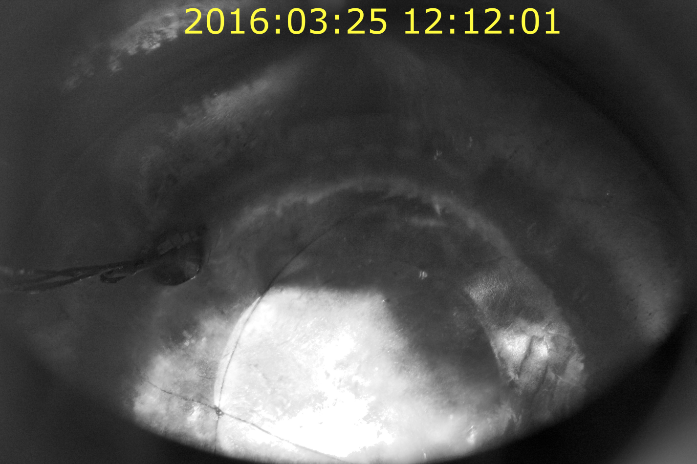
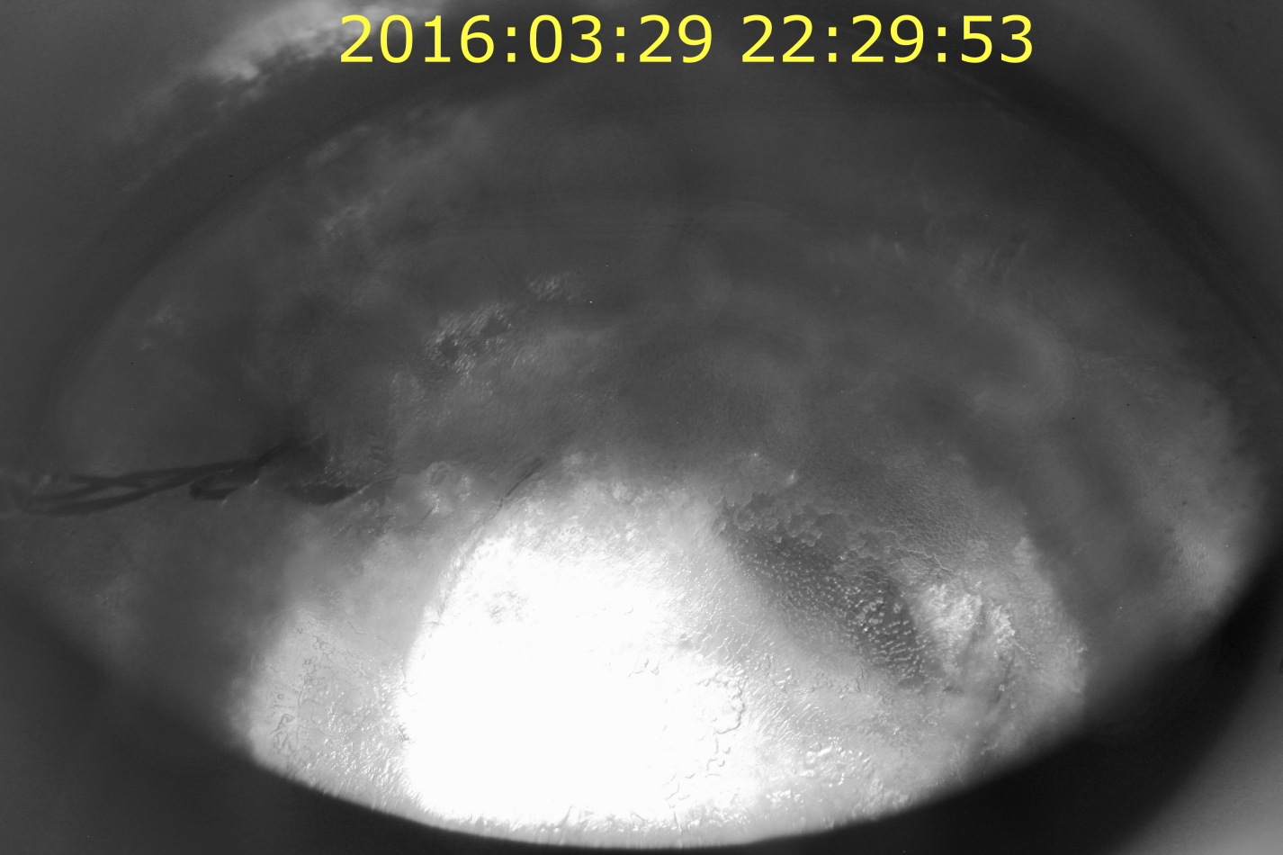
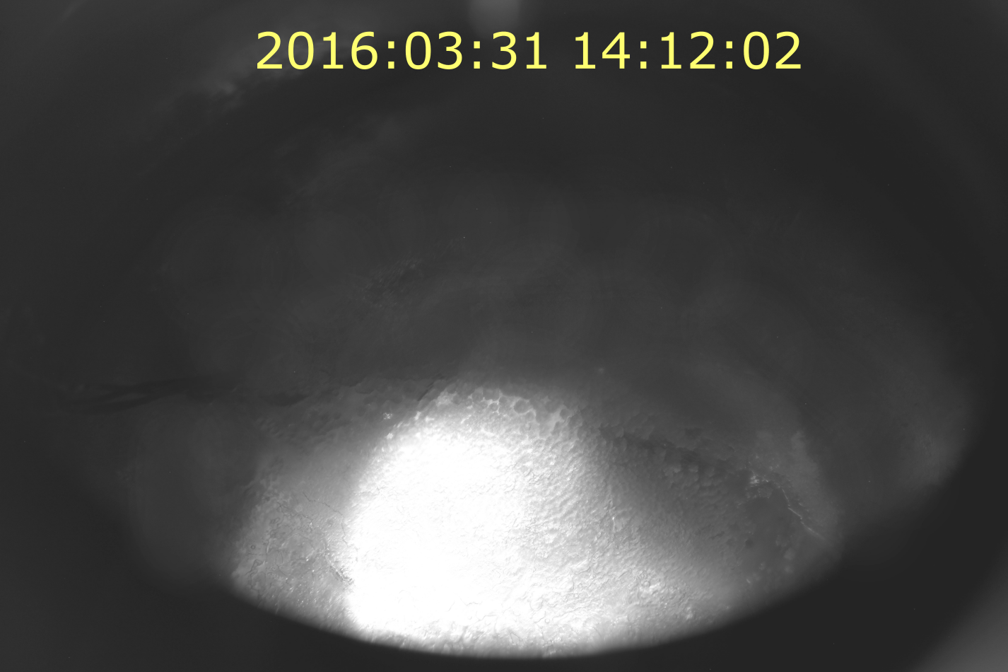
After heat pulsing, as shown in Fig. 14-bottom, the surface of the solid in the center looks very opaque and covered with some structured frost. Figure 15 shows a zoomed and post-processed image of the frost. From the dimensions of the T-sensor holder (diameter 10 mm) we have estimated that the visible large structures are about 1 mm in scale, assuming that the vertical scales of structures are similar to the horizontal ones.

3 Simulation and interpretation of experimental observations
A combination of measurements during UCN source operation (Sec. 2.1), optical observations (Sec. 2.3), and simulations, as described below, strongly support the hypothesis of the surface origin of the UCN yield diminution.
In general, there are three ways that surface degradation can affect UCN transport. Firstly, a top surface with a roughness on the scale of the UCN wavelength can change the shape of the neutron optical (Fermi) potential from a sharp step to a smooth profile. This can slightly affect reflection and transmission.
Secondly, the surface can broaden the angular distribution of UCN due to scattering from fluctuations in the density near the surface layer on scales much smaller than a typical crystal facet. In this case, one typically describes surface interactions via two components: a “specular” interaction with the average surface (facet) potential which obeys optical reflection laws (Eq.’s 1 and 2), and a component of “non-specular scattering” which results from density fluctuations about the flat facet surface (essentially independent of the elastic scattering mean free path in bulk sD2). Non-specular scattering in UCN transport is often described by a Lambertian angular distribution with respect to the surface normal Golub1991 ; Ignatovich1990 ; Zsigmond2018 , parametrized by a single constant, the average probability of non-specular scattering (see Atchison2010 and references therein for details on models for surface scattering for different distance scales and surface topologies).
Finally, a layer of frost detached from the bulk will introduce an albedo effect resulting from scattering from randomly oriented crystal facets on the complex topology of a frost-covered surface Kelly91 . When entering a facet, the neutron must have sufficient energy perpendicular to the facet to penetrate the potential barrier presented by the surface Fermi potential. When leaving the material, the UCN receives an energy boost in the direction perpendicular to the Fermi potential. Because the facets are oriented randomly, the result is increasingly like a diffusion problem as the number of encountered facets increases, with the flux through the frost more rapidly attenuated for low energy UCN.
The last two effects were simulated by the NCSU and PSI groups using different UCN transport codes. In the NCSU model, the effects of specular scattering on multiple layers of frost covered with randomly oriented facets are explored, as well as the impact of a simplified, Lambertian model of non-specular scattering at each facet face. The PSI model relies entirely on specular scattering from facets.
The details of these models are rather different, but the generic behavior is very similar: UCN interacting with successive layers of frost experience an incremental loss in the UCN flux observed above the frost layer, with the largest losses for the lowest energy UCN.
In order to study the effect of repeated reflections at interfaces between sD2 and vacuum, the simulations used the optical laws of reflection (R) and transmission (T) of UCN Ignatovich1990 . The corresponding probabilities PT and PR are given by
| (1) |
| (2) |
where 102 neV is the change in Fermi potential at the interface, , with being the velocity perpendicular to the interface, the perpendicular part of the kinetic energy in vacuum or within the material before the interaction. These equations are valid for every energy below or above . We neglected UCN losses since the UCN are only reflected a few times when passing the frost layer while the probability of loss per reflection is typically below Bondar2017 .
3.1 Simulations of rough and flat frost layers
In simulations of UCN transport through bulk sD2 and frost layers the NCSU team explored a number of effects and parameters using a very simple source geometry, similar to the LANL source cryostat, but without long guide system external to the cryostat.
All simulations were performed with a full energy spectrum: an initial velocity distribution according to the low energy tail of the Maxwell-Boltzmann distribution was used:
| (3) |
with UCN velocities covering a range at the point of production in the deuterium between 0 and 8 m/s, more than covering the energy range of storable UCN in the guide system.
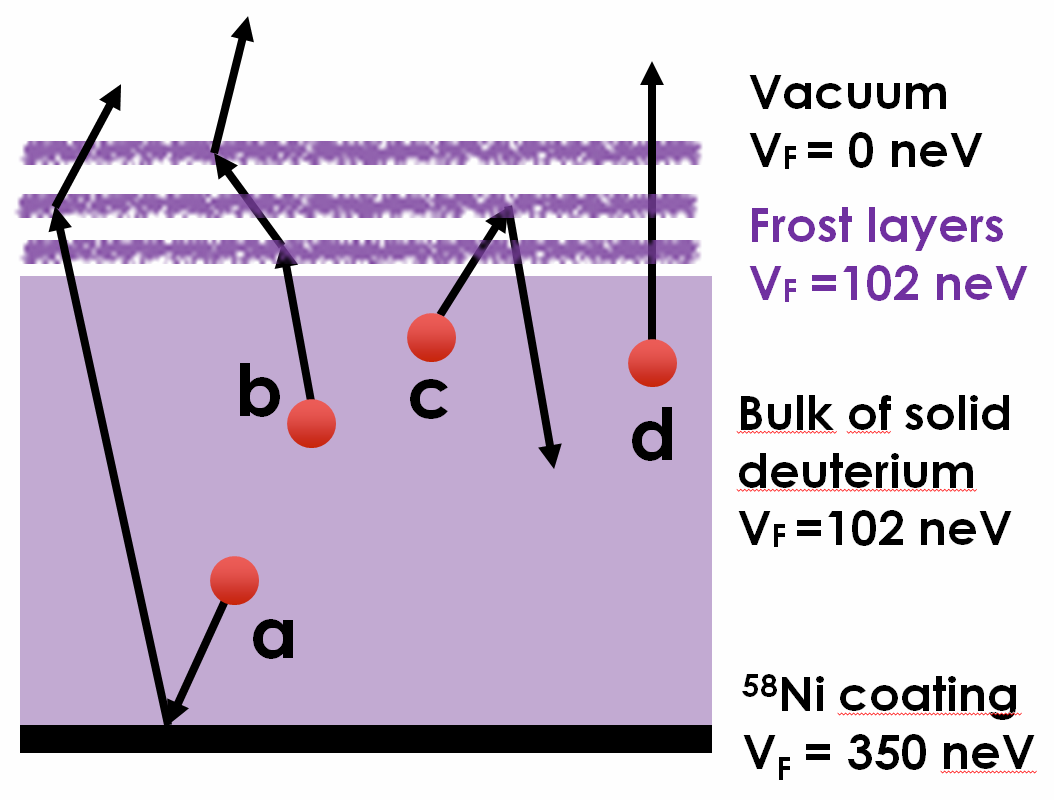
UCN were produced homogeneously throughout the bulk sD2 volume of the source, with initial velocities directed isotropically in the top hemisphere, and the yield, or probability of detection above the snow layers, was determined. For UCN transport through the bulk we assumed the sD2 to be homogeneous, with a total neutron life time (due to absorption and upscattering) of 40 ms and an elastic scattering mean free path = 4 cm. These values are adopted from LANL source characterization data, in which Monte-Carlo is used to connect crystal parameters to the measured UCN yield as a function of storage time in contact with the solid deuterium and the amount of deuterium in the source (as described, for example, in Morris2002 ; Saunders2004 ; LANL2013 ). These values should therefore be a reasonable starting point for our simulations, but we also explore the impact of varying source conditions as a part of the studies presented in this section.
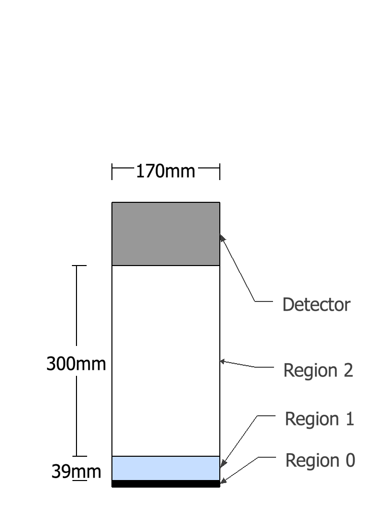
A simplified geometry, depicted in Fig. 16, was used for the simulations in this Section. The sD2 source was situated as a 3.9 cm thick volume at the bottom of a straight guide whose diameter matched the PULSTAR UCN cryostat guides (region 0). The bottom surface of the source was taken to be a 58Ni surface with Fermi potential neV (with all neutrons which are not reflected from the 58Ni assumed to be absorbed). The cylindrical walls of all regions were also assumed to be coated with 58Ni. A virtual detector was placed above the frost layers, modeled as a 100% absorbing surface. UCN incident on this surface were counted as “detected” and their trajectories terminated.
The goal of the first simulation was to confirm that scattering from multiple frost layers is needed to produce the experimentally observed reduction in UCN yield. We compared the probability to detect UCN above the sD2 bulk for two cases assuming no frost layers above the surface and either (i) a perfect flat surface for the solid, and (ii) a single faceted interface between the sD2 and guide vacuum, with the facets modeled by isotropically (described in more detail in the next paragraph) distributing the direction of the surface normal at the point of interaction with the UCN. UCN reaching a virtual detector above the frost layer, modeled as a completely absorbing disk, we tallied as “detected” and contributed to the yield. The results showed less than a 7% difference in the neutron yield. Consequently, scattering from a single layer of facets on the surface of the bulk sD2 can be ruled out as a cause for decreasing UCN yield from the source.
As a next step, frost structures were added between region 1 and 2 (see Fig. 16) by alternating layers of vacuum and sD2 (=102 neV) regions parallel to the solid surface, as shown in Fig. 17. Scattering was assumed to occur from both sides of each layer due to randomly oriented facets and (when implemented) from non-specular scatter. The surface normal was selected isotropically, but the angular range of the normal was constrained such that reflection at a boundary layer prevented the UCN from proceeding vertically into the next frost (or vacuum) layer. While simplistic and not exactly reproducing the effect of random orientation of “facets” of sD2 frost crystals, this model allows studies of the dependence of successive UCN scattering from vacuum/frost and frost/vacuum interfaces on conditions in the bulk sD2 and the frost layers.
The thickness of each sD2 and vacuum layer was chosen arbitrarily to be 10 microns to be roughly consistent with horizontal dimensions of optically observed features when many layers are present (features down to fractions of a millimeter were evident after heat pulsing). Losses and elastic scattering within the layers were confirmed to be negligible for the full range of UCN lifetimes and elastic scattering mean free paths considered for the bulk deuterium (presented below).
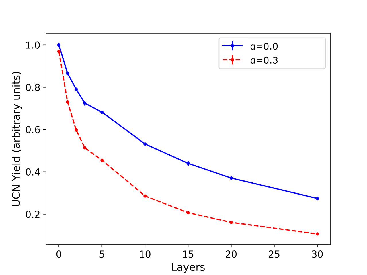
In the first study with frost, the correlations of the UCN yield with the number of sD2 layers was calculated by alternating 10 micron vacuum and deuterium layers. The results shown in Fig. 18 demonstrate an exponential attenuation of the neutron yield, with pure specular scattering from facet surfaces (this corresponds to for our crude model of non-specular scattering). We also attempt to show the potential impact of non-specular scattering by adding the effects of rough surfaces to our randomly oriented facet surfaces’ with a second curve with , corresponding to a rough surface. As discussed in Sec. 3, non-specular scattering results from roughness on the surface of a given facet. Of course, the surface profile for frost facets is an unknown function of the vapor flux, temperature variations, and crystal history, for example, but to clearly illustrate the impact of this scattering, we selected a value of . For reference, for highly polished guide materials, is of order 0.03 or smaller Atchison2010 . Non-specular scattering was described by a Lambertian angular distribution with respect to the surface normal. The angular distribution after non-specular scattering was also taken to be Lambertian. Because our model of non-specular scattering does not depend on the energy of the UCN incident on the surface (but specular reflection from randomly oriented facets more strongly affects the lowest energy UCN) and our facet model features a restricted range of facet orientations, it is evident that non-specular scatter at frost surfaces can increase the attenuation of the UCN flux, but does not change the qualitative picture of successive layers of frost incrementally reducing the UCN yield. Given that purely specular scattering appears to capture the essential physics of transport through the frost layers, we restrict our analysis from this point forward to specular scattering ().
Next we studied the dependence of the yield on the frost layer Fermi potential (which is proportional to the frost density). Fermi potentials of 100%, 66% and 33% of that for bulk sD2 were simulated. We found, as expected, that the yield losses scaled with the Fermi potential.
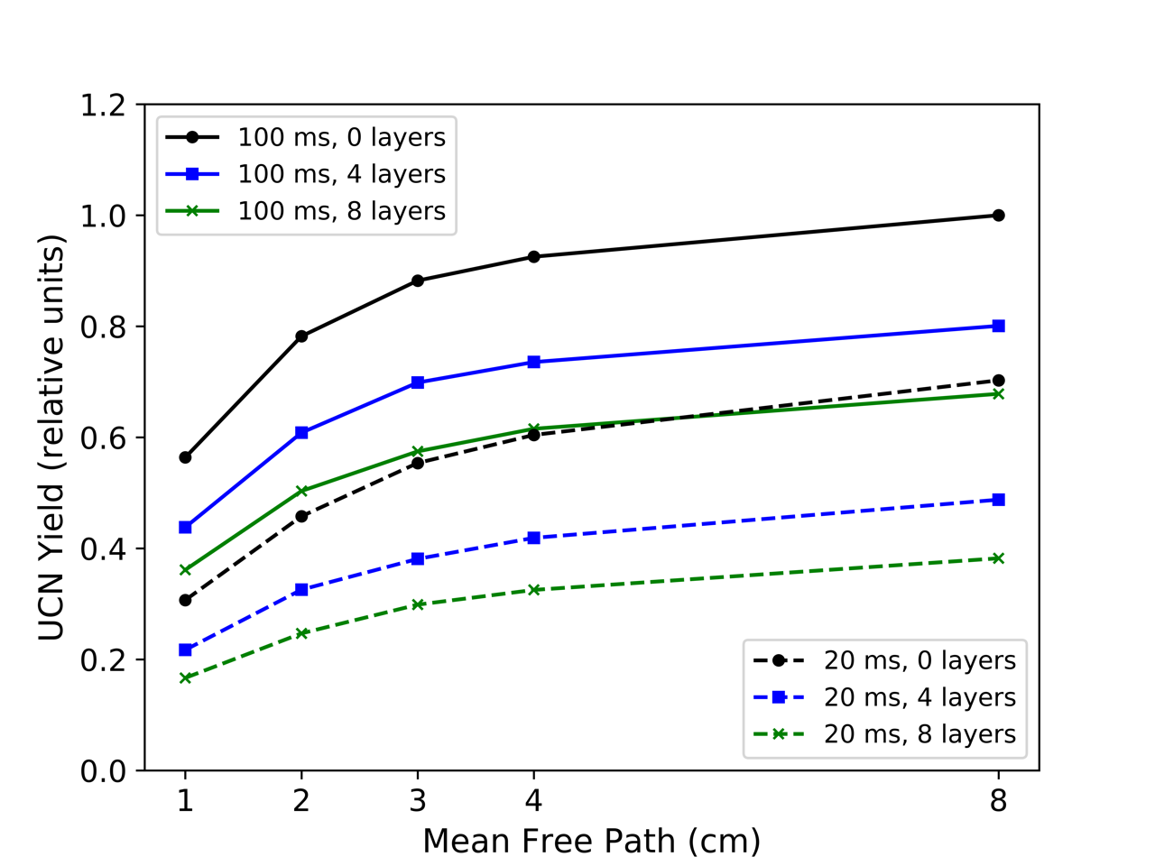
Since the main effect of frost is reflecting neutrons back to the bulk, the UCN yield should be dependent (at some level) on the bulk properties of sD2 We have explored this effect by varying neutron life time and mean free path in the bulk sD2. Results for two values of 20 ms and 100 ms are presented in Fig. 19. For 100 ms, the UCN yield through 4 layers of frost is higher then in the case of no frost with 20 ms. Note that, because of the very small volume in the frost layers, no dependence was observed on bulk sD2 properties in the frost layers themselves, only in the sD2 source volume.
Changes in the bulk sD2 properties may explain the observed scatter in the starting source performance after each melt-and-refreeze, and has some influence on the efficiency with which successive layers reduce the source output and and produce spectral hardening. The relative impact on source performance of the bulk sD2 properties, together with the integrated beam power, volume of solid deuterium in the source, physical configuration of the bulk sD2 (how much deuterium ends up on the side walls of the source below the flapper valve, for example) after a melt and refreeze, the vapor density above the sD2 and the cryogenic operating conditions for the source are under continuing investigation. These variables can also explain the spread in the attenuation slopes in the LANL data, but they also make exact simulations of the LANL source more challenging, by adding additional free parameters. Note that, although the UCN lifetime in the bulk varied rather slowly over the course of many months of LANL running, each melt and refreeze can, in principle, produce large variations in the effective elastic scattering mean free path in the bulk as reported in various studies Serebrov2001b ; Atchison2005b ; Atchison2011 .
Another simulation was performed to study the effect of the frost on the detected neutron energy spectrum while varying the number of layers. Results are shown in Fig. 20. The spectra are normalized to unit area for better comparison of their shape.
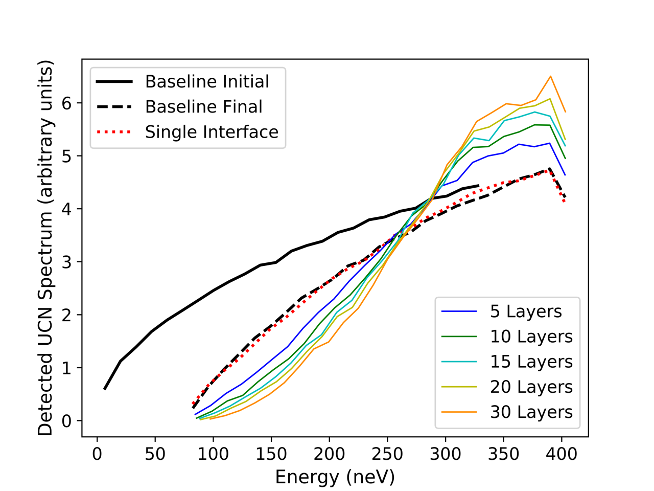
Two conclusions can be drawn. Firstly and most importantly, there is clear evidence of spectral hardening with increasing number of frost layers. Secondly, spectral hardening effects, which were experimentally observed at PSI and LANL, cannot be explained by a single rough interface between deuterium and vacuum. It should be noted that, in order to track the effect of successive interactions with frost layers, the frost layers cover the entire guide cross section in this first model and hence represent a limiting case of sorts. This simple model for interactions with the bottom surface of a frost layer (where UCN either enter the frost layer or are reflected down towards the sD2 source, but reflections from the “edge” of a frost feature which scatter UCN upward are not possible) results in gradual losses in UCN yield and correlated “hardening” of the spectrum, as observed for both LANL and PSI sources. Of course, voids or “holes” in the frost layers or reduced layer density can be incorporated into this model, accommodating a continuous variation of the impact of frost layers from no frost at all to many completely covering layers, but the characteristic, correlated spectral hardening and reduction in yield should always be present.
A more flexible model of the PSI source presented in the next section incorporates isotropic, random reflections from each frost surface, and variable coverage of scatterers permits tuning the impact of the frost layers on transmission and spectral hardening to accurately reproduce the measured performance of the PSI source.
3.2 Simulation and interpretation of the PSI measurements
In order to examine the fraction of UCN transmitted through a frost layer, the reflection from frost (snow) particles was modeled in 3D by using the MCUCN code Zsigmond2018 . The model describes the effect of reflections due to the optical potential step between sD2 and vacuum as described by the quantum reflection and transmission laws above, eqs. (1)–(2).
The geometry consisted of a large number of small sD2 disks distributed isotropically in orientation and homogeneously over the source surface, and several disk-radius units above the bulk, see Fig. 21. The vertical density distribution of the disks turned out to be irrelevant. The main assumption to the disk thickness was that (i) it is thin enough to neglect nuclear absorption or up-scattering since the mean-free-path associated with these losses is much larger; (ii) it is thicker than several UCN wavelengths, so that assuming sD2 bulk density, an optical potential 102 neV can be used for the material without allowing for quantum tunneling.
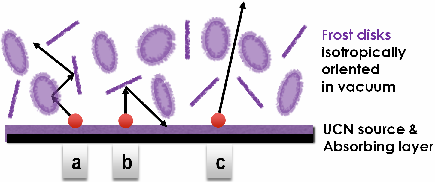
Multiple reflections within the disks between two faces were neglected, since this is a second order effect. Only specular reflections were considered because the isotropic angular distribution of the disks already accounts for a perfect diffuse redistribution after reflection. The number of disks was varied up to several thousand. The radius of the disks was varied in order to show that only the total surface of all disks normalized to the cross section of the sD2 converter is relevant. Doubling the disk radius was found equivalent to a four times lower number of sD2 disks.
In order to obtain the net transmission of only the disks layer, the virtual UCN source (a diffuse emitter) was set to perfectly absorb back-reflected particles. The effect of the energy boost from a perfectly flat sD2 surface was also compared to the case of an isotropically boosting emitter with a rough surface. The latter is equivalent to the case of no vertical boost but a final energy higher by 102 neV. The lateral boundary of this geometry was a cylindrical guide. This was set to have an ideally high optical potential, and the loss and diffuse reflection parameters were set to zero.
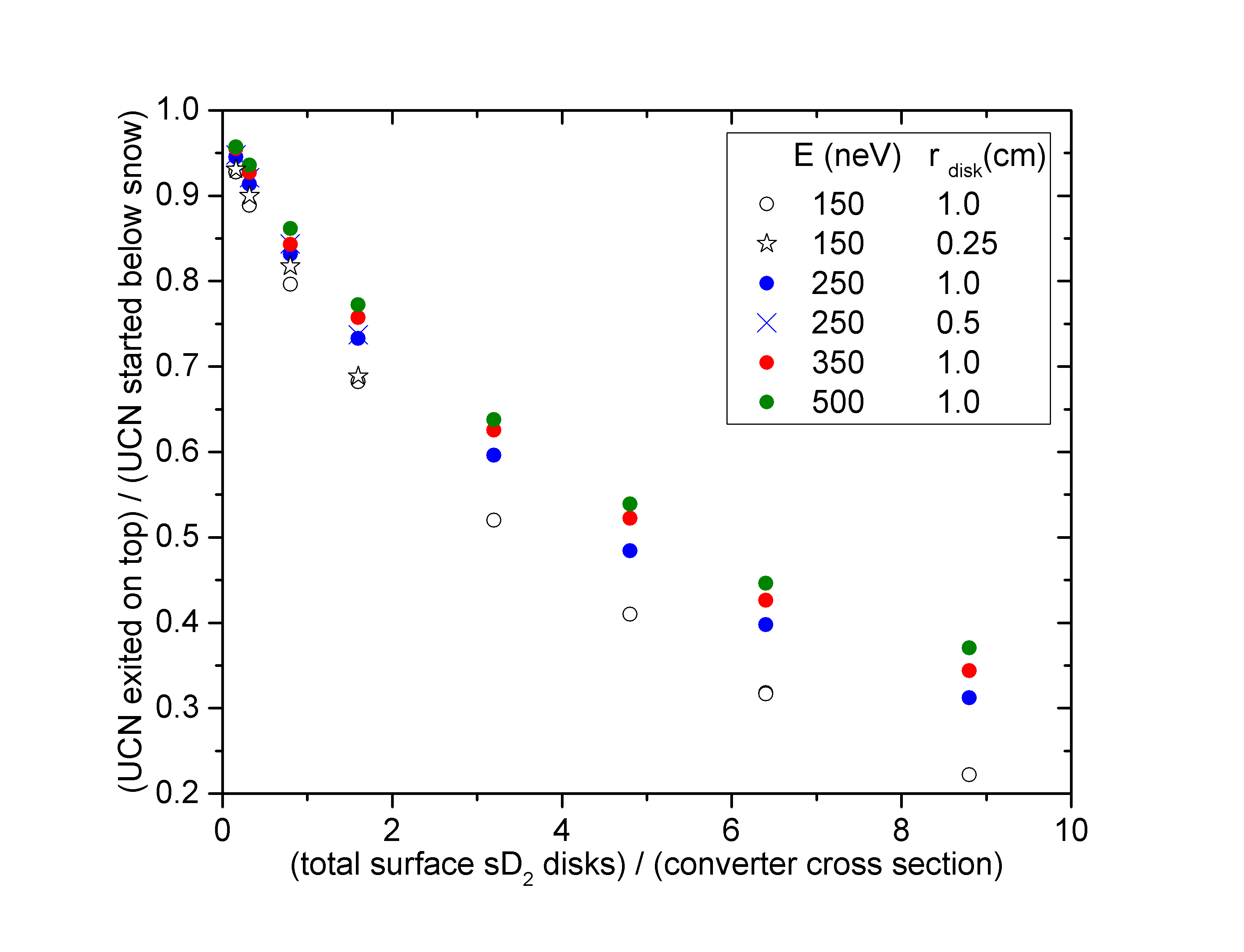
The calculated transmission is shown in Fig. 22 for various neutron energies as a function of the total sD2 frost surface. The UCN transmission of the sD2 disks layer is given by the ratio of the number of transmitted to incident UCN. The horizontal axis is the ratio of the total surface of all disks, and the cross section of the virtual source (and the cylinder guide). These results show that the UCN transmission decreases with increasing frost layer surface. The energy dependence indicates that such a reflecting layer attenuates slower UCN more strongly. Even a low surface ratio can cause a large UCN loss only due to back-reflections from randomly oriented interfaces between sD2 and vacuum.
These simulation results reproduce the magnitude of the decrease in UCN output observed after several days at the PSI UCN source. The decrease to 0.7 would be equivalent to a simulated surface ratio of about 2 (see Fig. 22). Furthermore, this corresponds to the amount of deuterium estimated in the conditioning treatment, equivalent to a layer thickness of approximately 500-1000 nm. This allows the disk layer thickness of sD2 to be 250 to 500 nm, i.e. about 4 wavelengths for 150 neV UCN. This thickness is large enough for the formation of a totally reflecting optical potential. The consistency of the measured and simulated values indicates that a frost scenario is realistic.
This model can explain the decrease shown in Fig. 1, Fig. 7 and in Fig. 8. UCN extracted in West-2 are emitted by the sD2 with energies much larger than its optical potential and are consequently less affected by the frost layer.
4 Summary
The existing pulsed UCN spallation sources based on sD2 converters suffer from a significant, energy dependent decrease in UCN intensity with increasing number of pulses after initial preparation of the sD2. This preparation can be melting and refreezing of the total material (at LANL, with change of the sD2 bulk properties) or a special heat treatment of the solid called “conditioning” (at PSI, likely without change of the sD2 bulk properties).
We have presented energy dependent UCN intensity measurements at the pulsed PSI and LANL UCN sources, which show the lower the neutron energy, the stronger the attenuation. Together with correlated measurements of temperatures and D2 vapor pressures during pulse operation and during conditioning (at PSI), all of the data pointed towards the build-up of frost layers on the sD2 surface as most realistic explanation for reduced intensity with larger pulsed heating. Pulses cause sublimation of D2 with resublimation at a different temperature during and after the pulse.
Optical observations of sD2 at the PULSTAR UCN source setup have been performed by applying heat pulses with a resistance heater. The heat pulses were adjusted to have profiles similar to those measured from the beam heating at the operating UCN sources. These observations clearly demonstrate the adverse effects on the surface quality of the sD2 from the pulsed heating, which turns from completely optically transparent to opaque and structured.
Transport simulations through the frost layers were performed by both, the NCSU (for a simple geometry similar to LANL source cryostat only) and PSI teams (using a more realistic frost model). The NCSU simulations were performed to explore general parameter dependencies of the UCN yield when frost is present, including dependence of frost attenuation on the crystal bulk properties. The PSI simulation was able not only to explain the observed count rate decrease but also to extract realistic frost parameters.
The UCN measurements at PSI are very well described by the PSI model. The frost layers are simulated by isotropically oriented sD2 disks accumulating on the D2 surface. UCN can undergo reflections from all surfaces on their path. The simulation shows that the UCN transmission through the layers of disks depends on the UCN kinetic energy and the surface ratio of all disks relative to the converter area and that the transmission is independent of size and shape of the disks. As the total surface area of the disks grows (corresponding to more pulses and longer operating time) the UCN transmission is decreasing due to increased albedo reflection.
In conclusion, the complete set of UCN counting data, optical observations and different simulation models support surface frost formation as the explanation for UCN yield decline with time at pulsed UCN sources. This deterioration is correlated to the pulsed heat deposition, which leads to material transport and reorganization on the sD2 surface. A better understanding of the cause may allow further improving the conditioning process or even controlling the sD2 conditions under pulsed operation in a way that avoids the build-up of frost layers.
Acknowledgments
This work was supported in part by the US Department of Energy under Grant No. DE-FG02-97ER41042 and the US National Science Foundation under grant number NSF-1615153. PSI acknowledges the support by the Swiss National Science Foundation Projects 200020_137664, 200020_149813, and 200020_163413, support by the proton accelerator operations and UCN source operations groups, support by P. Erismann, M. Meier and C. Zoller, and access to the computing grid infrastructure PL-Grid PLGrid . We acknowledge Jan Bacca for helping proof read the paper.
References
- [1] R. Golub, D.J. Richardson, and S.K. Lamoreaux. Ultra-Cold Neutrons. Adam Hilger, Bristol, Philadelphia, and New York, 1991.
- [2] H. Abele. The neutron. Its properties and basic interactions. Prog. Part. Nucl. Phys., 60:1–81, January 2008.
- [3] D. Dubbers and M.G. Schmidt. The neutron and its role in cosmology and particle physics. Rev. Mod. Phys., 83:1111–1171, October 2011.
- [4] I.S. Altarev, Yu.V. Borisov, A.B. Brandin, V.F. Ezhov, S.N. Ivanov, G.K. Kunstman, V.M. Lobashev, V.A. Nazarenko, V.L. Ryabov, A.P. Serebrov, and R.R. Taldaev. A liquid hydrogen source of ultra-cold neutrons. Phys. Letters A, 80(5):413–416, 1980.
- [5] R. Golub and K. Boenig. New type of low temperature source of ultra-cold neutrons and production of continous beams of UCN. Z. Phys. B, 51:95, 1983.
- [6] S.S. Yu, Z.-Ch.and Malik and R. Golub. A thin film source of ultra-cold neutrons. Z. Phys. B, 62:137, 1986.
- [7] A. Steyerl, H. Nagel, F.-X. Schreiber, K.-A. Steinhauser, R. Gaehler, W. Glaeser, P. Ageron, J.M. Astruc, W. Drexel, G. Gervais, and W. Mampe. A new source of cold and ultracold neutrons. Phys. Lett. A, 116(7):347 – 352, 1986.
- [8] R. Golub and J.M. Pendlebury. The interaction of Ultra-Cold Neutrons (UCN) with liquid helium and a superthermal UCN source. Phys. Lett. A, 62(5):337–339, 1977.
- [9] A.P. Serebrov, V.A. Mityukhlyaev, A.A. Zakharov, V.V. Nesvizhesvsky, and A.G. Kharitonov. Is it possible to produce next generation of UCN sources with a density 10-3 – 10-4 cm-3 ? JETP Lett., 59:757, 1994.
- [10] A. P. Serebrov, V. A. Mityukhlyaev, A. A. Zakharov, A.G. Kharitonov, V.V. Nesvizhesvsky, M.S. Lasakov, R.R. Tal’daev, A.V. Aldushchenkov, A.V. Varlamov, V.E.and Vasil’ev, G. Greene, and T. Bowles. Experimental study of a solid-deuterium source of ultracold neutrons. JETP Lett., 62:785, 1995.
- [11] A. Serebrov, V. Mityukhlyaev, A. Zakharov, A. Kharitonov, V. Shustov, V. Kuz’minov, M. Lasakov, R. Tal’daev, A. Aldushchenkov, V. Varlamov, A. Vasil’ev, M. Sazhin, G. Greene, T. Bowles, R. Hill, S. Seestrom, and P. Geltenbort. Studies of a solid-deuterium source for ultra-cold neutrons. Nucl. Instrum. Methods A, 440(3):658–665, 2000.
- [12] A.P. Serebrov, E. A. Kolomenski, M. S. Lasakov, V. A. Mityukhlyaev, A. N. Pirozhkov, I. A. Potapov, E. Varlamov, A. V. Vasliev, Young A. R., and A. Zakharov. Experimental studies of very cold neutrons passing through solid deuterium. JETP Lett., 74:302, 2001.
- [13] Yu.N. Pokotilovski. Production and storage of ultacold neutrons at pulsed neutron sources with low repetition rates. Nucl. Instrum. Methods A, (356):412–414, 1995.
- [14] C. L. Morris, J. M. Anaya, T. J. Bowles, B. W. Filippone, P. Geltenbort, R. E. Hill, M. Hino, S. Hoedl, G. E. Hogan, T. M. Ito, T. Kawai, K. Kirch, S. K. Lamoreaux, C.-Y. Liu, M. Makela, L. J. Marek, J. W. Martin, R. N. Mortensen, A. Pichlmaier, A. Saunders, S. J. Seestrom, D. Smith, W. Teasdale, B. Tipton, M. Utsuro, A. R. Young, and J. Yuan. Measurements of ultracold-neutron lifetimes in solid deuterium. Phys. Rev. Lett., 89(27):272501, 2002.
- [15] A. Saunders, J.M. Anaya, T.J. Bowles, B.W. Filippone, P. Geltenbort, R.E. Hill, M. Hino, S. Hoedl, G.E. Hogan, T.M. Ito, K.W. Jones, T. Kawai, K. Kirch, S.K. Lamoreaux, C.-Y. Liu, M. Makela, L.J. Marek, J.W. Martin, C.L. Morris, R.N. Mortensen, A. Pichlmaier, S.J. Seestrom, A. Serebrov, D. Smith, W. Teasdale, B. Tipton, R.B. Vogelaar, A.R. Young, and J. Yuan. Demonstration of a solid deuterium source of ultra-cold neutrons. Phys. Lett. B, 593(1–4):55–60, July 2004.
- [16] C.-Y. Liu, A. R. Young, and S. K. Lamoreaux. Ultracold neutron upscattering rates in a molecular deuterium crystal. Phys. Rev. B, 62:R3581–R3583, 2000.
- [17] F. Atchison, B. van den Brandt, Brys T., M. Daum, P. Fierlinger, P. Hautle, R. Henneck, S. Heule, M. Kasprzak, K. Kirch, J. A. Konter, A. Michels, A. Pichlmaier, M. Wohlmuther, A. Wokaun, K. Bodek, U. Szerer, P. Geltenbort, J. Zmeskal, and Y. Pokotilovskiy. Production of ultracold neutrons from a cold neutron beam on a 2H2 target. Phys. Rev. C, 71(5):054601, May 2005.
- [18] F. Atchison, B. Blau, K. Bodek, B. van den Brandt, T. Brys, M. Daum, P. Fierlinger, A. Frei, P. Geltenbort, P. Hautle, R. Henneck, S. Heule, A. Holley, M. Kasprzak, K. Kirch, A. Knecht, J. A. Konter, M. Kuzniak, C.-Y. Liu, C. L. Morris, A. Pichlmaier, C. Plonka, Y. Pokotilovski, A. Saunders, Y. Shin, D. Tortorella, M. Wohlmuther, A. R. Young, J. Zejma, and G. Zsigmond. Cold neutron energy dependent production of ultracold neutrons in solid deuterium. Phys. Rev. Lett., 99(26):262502, 2007.
- [19] A. Frei, E. Gutsmield, C. Morkel, A.R. Mueller, S. Paul, S. Rols, H. Schober, and T. Unruh. Understanding of ultra-cold -neutron production in solid deuterium. Eur. Phys. Lett., 92:62001, 2010.
- [20] F. Atchison, B. Blau, B. van den Brandt, Brys T., M. Daum, P. Fierlinger, P. Hautle, R. Henneck, S. Heule, M. Kasprzak, K. Kirch, J. Kohlbrecher, G. Kuehen, J. A. Konter, A. Pichlmaier, A. Wokaun, K. Bodek, P. Geltenbort, and J. Zmeskal. Measured total cross sections of slow neutrons scattered by solid deuterium and implications for ultracold neutron sources. Phys. Rev. Lett., 95:182502, 2005.
- [21] F. Atchison, B. Blau, K. Bodek, B. van den Brandt, T. Brys, M. Daum, P. Fierlinger, A. Frei, P. Geltenbort, P. Hautle, R. Henneck, S. Heule, A. Holley, M. Kasprzak, K. Kirch, A. Knecht, J.A. Konter, M. Kuzniak, C.-Y. Liu, C.L. Morris, A. Pichlmaier, C. Plonka, Y. Pokotilovski, A. Saunders, Y. Shin, D. Tortorella, M. Wohlmuther, A.R. Young, J. Zejma, and G. Zsigmond. Production of ultracold neutrons from cryogenic 2H2, O2, and C2H4 converters. Eur.Phys.Lett, 95:1, 2011.
- [22] Yu.N. Pokotilovskyi. UCN transport simulation in solid deuterium crystals. Nucl. Instrum. Methods A, 675:29–33, 2012.
- [23] R.E. Hill, J.M. Anaya, T.J. Bowles, G.L. Greene, G. Hogan, S. Lamoreaux, L. Marek, R. Mortenson, C.L. Morris, A. Saunders, S.J. Seestrom, W. Teasdale, S. Hoedl, C.Y. Liu, D.A. Smith, A. Young, B.W. Filippone, J. Hua, T. Ito, E. Pasyuk, P. Geltenbort, A. Garcia, B. Fujikawa, S. Baessler, and A. Serebrov. Performance of the prototype LANL solid deuterium ultra-cold neutron source. Nucl. Instrum. Methods A, 440:674–681, 2000.
- [24] A. Saunders, M. Makela, Y. Bagdasarova, H. O. Back, J. Boissevain, L. J. Broussard, T. J. Bowles, R. Carr, S. A. Currie, B. Filippone, A. Garcia, P. Geltenbort, K. P. Hickerson, R. E. Hill, J. Hoagland, S. Hoedl, A. T. Holley, G. Hogan, T. M. Ito, Steve Lamoreaux, Chen-Yu Liu, J. Liu, R. R. Mammei, J. Martin, D. Melconian, M. P. Mendenhall, C. L. Morris, R. N. Mortensen, R. W. Pattie, M. Pitt, B. Plaster, J. Ramsey, R. Rios, A. Sallaska, S. J. Seestrom, E. I. Sharapov, S. Sjue, W. E. Sondheim, W. Teasdale, A. R. Young, B. VornDick, R. B. Vogelaar, Z. Wang, and Yanping Xu. Performance of the los alamos national laboratory spallation-driven solid-deuterium ultra-cold neutron source. Rev. Sci. Instr., 84(1):013304, 2013.
- [25] T. M. Ito, E.R. Adamek, N.B. Callahan, J.H. Choi, S.M. Clayton, C. Cude-Woods, S. Currie, X. Ding, D.E. Fellers, P. Geltenbort, S.K. Lamoreaux, C.Y. Liu, S. MacDonald, M. Makela, C.L. Morris, R.W. Pattie Jr., J.C. Ramsey, D.J. Salvat, A. Saunders, E.I. Sharapov, S. Sjue, A.P. Sprow, Z. Tang, H.L. Weaver, W. Wei, and Young A.R. Performance of the upgraded ultracold neutron source at Los Alamos National Laboratory and its implication for a possible neutron electric dipole moment experiment. Phys. Rev. C, 97:012501, 2018.
- [26] A. Anghel, F. Atchison, B. Blau, B. van den Brandt, M. Daum, R. Doelling, M. Dubs, P.-A. Duperrex, A. Fuchs, D. George, L. Göltl, P. Hautle, G. Heidenreich, F. Heinrich, R. Henneck, S. Heule, Th. Hofmann, St. Joray, M. Kasprzak, K. Kirch, A. Knecht, J.A. Konter, T. Korhonen, M. Kuzniak, B. Lauss, A. Mezger, A. Mtchedlishvili, G. Petzoldt, A. Pichlmaier, D. Reggiani, R. Reiser, U. Rohrer, M. Seidel, H. Spitzer, K. Thomsen, W. Wagner, M. Wohlmuther, G. Zsigmond, J. Zuellig, K. Bodek, S. Kistryn, J. Zejma, P. Geltenbort, C. Plonka, and S. Grigoriev. The PSI ultra-cold neutron source. Nucl. Instrum. Methods A, 611:272–275, 2009.
- [27] B. Lauss. A new facility for fundamental particle physics: The high-intensity ultracold neutron source at the Paul Scherrer Institute. AIP Conf. Proc., 1441(1):576–578, 2012.
- [28] B. Lauss. Startup of the high-intensity ultracold neutron source at the Paul Scherrer Institute. Hyperf. Int., 211:21–25, 2012.
- [29] B. Lauss. Ultracold Neutron Production at the Second Spallation Target of the Paul Scherrer Institute. Phys. Proc., 51:98, 2014.
- [30] H. Becker, G. Bison, B. Blau, Z. Chowdhuri, J. Eikenberg, M. Fertl, K. Kirch, B. Lauss, G. Perret, D. Reggiani, D. Ries, P. Schmidt-Wellenburg, V. Talanov, M. Wohlmuther, and G. Zsigmond. Neutron production and thermal moderation at the PSI UCN source. Nucl. Instrum. Methods A, 777(0):20–27, 2015.
- [31] G. Bison, M. Daum, K. Kirch, B. Lauss, D. Ries, P. Schmidt-Wellenburg, G. Zsigmond, T. Brenner, P. Geltenbort, T. Jenke, O. Zimmer, M. Beck, W. Heil, J. Kahlenberg, J. Karch, K. Ross, K. Eberhardt, C. Geppert, S. Karpuk, T. Reich, C. Siemensen, Y. Sobolev, and N. Trautmann. Comparison of ultracold neutron sources for fundamental physics measurements. Phys. Rev. C, 95(4):045503, 2017.
- [32] J. Karch, Yu. Sobolev, M. Beck, K. Eberhardt, G. Hampel, W. Heil, R. Kieser, T. Reich, N. Trautmann, and M. Ziegner. Performance of the solid deuterium ultra-cold neutron source at the pulsed reactor TRIGA mainz. Eur. Phys. J. A, 50(4):78, 2014.
- [33] J. Kahlenberg, D. Ries, K. U. Ross, C. Siemensen, M. Beck, C. Geppert, W. Heil, N. Hild, J. Karch, S. Karpuk, F. Kories, M. Kretschmer, B. Lauss, T. Reich, Y. Sobolev, and N. Trautmann. Upgrade of the ultracold neutron source at the pulsed reactor TRIGA mainz. The European Physical Journal A, 53(11):226–, 2017.
- [34] E. Korobkina, B.W. Wehring, A.I. Hawari, A.R. Young, P.R. Huffman, R. Golub, Y. Xu, and G. Palmquist. An ultracold neutron source at the NC state university PULSTAR reactor. Nucl. Instrum. Methods A, 579(1):530–533, 2007.
- [35] P. C. Souers. Hydrogen properties for fusion research. Univ. of California Press, Berkeley-Los Angeles-London, 1986.
- [36] K. Bodek, B. van den Brandt, T. Brys, M. Daum, P. Fierlinger, P. Geltenbort, M. Giersch, P. Hautle, R. Henneck, M. Kasprzak, K. Kirch, J.A. Konter, G. Kuehne, M. Kuzniak, K. Mishima, A. Pichlmaier, D. Raetz, A. Serebrov, and J. Zmeskal. An apparatus for the investigation of solid D2 with respect to ultra-cold neutron sources. Nucl. Instrum. Methods A, 533:491–504, 2004.
- [37] G. W. Collins, E. M. Fearon, E. R. Mapoles, R. T. Tsugawa, P. C. Souers, and P. A. Fedders. J =1 to J =0 conversion in solid D-T. Phys. Rev. B, 44:6598–6607, 1991.
- [38] M. Seidel, S. Adam, A. Adelmann, C. Baumgarten, Y.J. Bi, R. Doelling, H. Fitze, A. Fuchs, M. Humbel, J. Grillenberger, D. Kiselev, A. Mezger, D. Reggiani, M. Schneider, J.J. Yang, H. Zhang, T.J. Zhang. Production of a 1.3 MW proton beam at PSI. Proceedings of IPACұ0, Kyoto, Japan, TUYRA03:1309, 2010.
- [39] M. Wohlmuther and G. Heidenreich. The spallation target of the ultra-cold neutron source UCN at PSI. Nucl. Instrum. Methods A, 564:51, 2006.
- [40] K. Kirch, B. Lauss, P. Schmidt-Wellenburg, and G. Zsigmond. Ultracold neutrons - physics and production. Nucl. Phys. News, 20:17–23, 2010.
- [41] F. Atchison, B. Blau, K. Bodek, B. van den Brandt, T. Brys, M. Daum, P. Fierlinger, A. Frei, P. Geltenbort, P. Hautle, R. Henneck, S. Heule, A. Holley, M. Kasprzak, K. Kirch, A. Knecht, J.A. Konter, M. Kuzniak, C.-Y. Liu, C.L. Morris, A. Pichlmaier, C. Plonka, Y. Pokotilovski, A. Saunders, Y. Shin, D. Tortorella, M. Wohlmuther, A.R. Young, J. Zejma, and G. Zsigmond. Investigation of solid D2, O2 and CD4 for ultracold neutron production. Nucl. Instrum. Methods A, 611(2):252–255, 2009.
- [42] A. P. Serebrov, V. A. Mityukhlyaev, A. A. Zakharov, T. Bowles, G. Greene, and J. Sromicki. Solid deuterium source of ultracold neutrons based on a pulsed spallation source. JETP Lett., 66:802–808, 1997.
- [43] A.R. Young, S. Clayton, B. W. Filippone, P. Geltenbort, T. M. Ito, C.-Y. Liu, M. Makela, C. L. Morris, B. Plaster, A. Saunders, S. J. Seestrom, and R. B. Vogelaar. Beta decay measurements with ultracold neutrons: a review of recent measurements and the research program at los alamos national laboratory. J. Phys. G.: Nucl. Part. Phys., 41:114007, 2014.
- [44] V. Talanov. Numerical monte carlo simulation and parametrization of the deposited energy density distribution in the solid deuterium moderator of the UCN source. Technical report, Paul Scherrer Institute TM-85-17-09, 2017.
- [45] I. Altarev, F. Atchison, M. Daum, A. Frei, E. Gutsmiedl, G. Hampel, F. J. Hartmann, W. Heil, A. Knecht, J. V. Kratz, T. Lauer, M. Meier, S. Paul, Y. Sobolev, and N. Wiehl. Direct experimental verification of neutron acceleration by the material optical potential of solid . Phys. Rev. Lett., 100(1):014801–, 2008.
- [46] I. Altarev, M. Daum, A. Frei, E. Gutsmiedl, G. Hampel, F. J. Hartmann, W. Heil, A. Knecht, J. V. Kratz, T. Lauer, M. Meier, S. Paul, U. Schmidt, Y. Sobolev, N. Wiehl, and G. Zsigmond. Neutron velocity distribution from a superthermal solid 2H2 ultracold neutron source. Eur. Phys. J. A, 37(1):9–14, 2008.
- [47] B. Blau, M. Daum, M. Fertl, P. Geltenbort, L. Goeltl, R. Henneck, K. Kirch, A. Knecht, B. Lauss, P. Schmidt-Wellenburg, and G. Zsigmond. A prestorage method to measure neutron transmission of ultracold neutron guides. Nucl. Instrum. Methods A, 807:30 – 40, 2016.
- [48] C.A. Baker, G. Ban, K. Bodek, M. Burghoff, Z. Chowdhuri, M. Daum, M. Fertl, B. Franke, P. Geltenbort, K. Green, M.G.D. van der Grinten, E. Gutsmiedl, P.G. Harris, R. Henneck, P. Iaydjiev, S.N. Ivanov, N. Khomutov, M. Kasprzak, K. Kirch, S. Kistryn, S. Knappe-Gruneberg, A. Knecht, P. Knowles, A. Kozela, B. Lauss, T. Lefort, Y. Lemiere, O. Naviliat-Cuncic, J.M. Pendlebury, E. Pierre, F.M. Piegsa, G. Pignol, G. Quemener, S. Roccia, P. Schmidt-Wellenburg, D. Shiers, K.F. Smith, A. Schnabel, L. Trahms, A. Weis, J. Zejma, J. Zenner, and G. Zsigmond. The search for the neutron electric dipole moment at the Paul Scherrer Institute. Physics Proc., 17(0):159 – 167, 2011. 2nd International Workshop on the Physics of fundamental Symmetries and Interactions - PSI2010.
- [49] J. M. Pendlebury, S. Afach, N. J. Ayres, C. A. Baker, G. Ban, G. Bison, K. Bodek, M. Burghoff, P. Geltenbort, K. Green, W. C. Griffith, M. van der Grinten, Z. D. Grujić, P. G. Harris, V. Hélaine, P. Iaydjiev, S. N. Ivanov, M. Kasprzak, Y. Kermaidic, K. Kirch, H.-C. Koch, S. Komposch, A. Kozela, J. Krempel, B. Lauss, T. Lefort, Y. Lemière, D. J. R. May, M. Musgrave, O. Naviliat-Cuncic, F. M. Piegsa, G. Pignol, P. N. Prashanth, G. Quéméner, M. Rawlik, D. Rebreyend, J. D. Richardson, D. Ries, S. Roccia, D. Rozpedzik, A. Schnabel, P. Schmidt-Wellenburg, N. Severijns, D. Shiers, J. A. Thorne, A. Weis, O. J. Winston, E. Wursten, J. Zejma, and G. Zsigmond. Revised experimental upper limit on the electric dipole moment of the neutron. Phys. Rev. D, 92:092003, Nov 2015.
- [50] R. W. Jr. Pattie, N. B. Callahan, C. Cude-Woods, E. R. Adamek, L. J. Broussard, S. M. Clayton, S. A. Currie, E. B. Dees, X. Ding, E. M. Engel, D. E. Fellers, W. Fox, K. P. Hickerson, M. A. Hoffbauer, A. T. Holley, A. Komives, C.-Y. Liu, S. W. T. MacDonald, M. Makela, C. L. Morris, J. D. Ortiz, J. Ramsey, D. J. Salvat, A. Saunders, S. J. Seestrom, E. I. Sharapov, S. K. Sjue, Z. Tang, J. Vanderwerp, B. Vogelaar, P. L. Walstrom, Z. Wang, W. Wei, H. L. Weaver, J. W. Wexler, T. L. Womack, A. R. Young, and B. A. Zeck. Measurement of the neutron lifetime using an asymmetric magneto- gravitational trap and in situ detection. arXiv:1707.01817, 2017.
- [51] E. Korobkina, G. Medlin, B. Wehring, A.I. Hawari, P.R. Huffman, A.R. Young, B. Beaumont, and G. Palmquist. Ultracold neutron source at the PULSTAR reactor: Engineering design and cryogenic testing. Nucl. Instrum. Methods A, 767(0):169 – 175, 2014.
- [52] G. Medlin. Characterization of the PULSTAR Ultracold Neutron Source. PhD thesis, North Carolina State University, Raleigh, USA, 2017.
- [53] V.K. Ignatovich. The Physics of Ultracold Neutrons. Clarendon, Oxford, 1990.
- [54] G. Zsigmond. The MCUCN simulation code for ultracold neutron physics. Nucl. Instrum. Methods A, 881:16–26, 2018.
- [55] F. Atchison, M. Daum, R. Henneck, S. Heule, M. Horisberger, M. Kasprzak, K. Kirch, A. Knecht, M. Kuzniak, B. Lauss, A. Mtchedlishvili, M. Meier, G. Petzoldt, C. Plonka-Spehr, R. Schelldorfer, U. Straumann, and G. Zsigmond. Diffuse reflection of ultracold neutrons from low-roughness surfaces. The European Physical Journal A, 44(1):23–29, 2010.
- [56] A. Kelly and G. W. Groves. Crystalography and Crystal Defects. Techbooks, 1991.
- [57] V. Bondar, S. Chesnevskaya, M. Daum, B. Franke, P. Geltenbort, L. Goeltl, E. Gutsmiedl, J. Karch, M. Kasprzak, G. Kessler, K. Kirch, H.-C. Koch, A. Kraft, T. Lauer, B. Lauss, E. Pierre, G. Pignol, D. Reggiani, P. Schmidt-Wellenburg, Yu. Sobolev, T. Zechlau, and G. Zsigmond. Losses and depolarization of ultracold neutrons on neutron guide and storage materials. Phys. Rev. C, 96(3):035205–, 2017.
- [58] Polish Grid Infrastructure, http://www.plgrid.pl/en.