Subwavelength Interferometric Control of Absorption in Three-port Acoustic Network
Abstract
Utilizing the effect of losses, we show that symmetric 3-port devices exhibit coherent perfect absorption of waves and we provide the corresponding conditions on the reflection and transmission coefficients. Infinite combinations of asymmetric inputs with different amplitudes and phase at each port as well as a completely symmetric input, are found to be perfectly absorbed. To illustrate the above we study an acoustic 3-port network operating in a subwavelength frequency both theoretically and experimentally. In addition we show how the output from a 3-port network is altered, when conditions of perfect absorption are met but the input waves phase and amplitude vary. In that regard, we propose optimized structures which feature both perfect absorption and perfect transmission at the same frequency by tuning the amplitudes and phases of the input waves.
Introduction
The absorption of wave energy is a phenomenon which underlies many applications in acoustics and photonics including molecular sensing [1, 2], photodetection [3], and sound proofing [4, 5]. By exploring wave interference, the absorption can become much more efficient or even complete. Indeed, coherent perfect absorbers have been extensively studied the last years in different photonic [6, 8, 7, 9, 10, 11, 12, 13] and acoustic [14, 15, 16] structures. However, the majority of these works deals with two-port systems. Especially in acoustics, the phenomenon of perfect absorption has attracted great attention the last years due to its direct applications to numerous noise reduction problems. Many solutions have been proposed in the low frequency regime based on subwavelength metamaterial designs, by critically coupling [17] resonant scatterers to the waveguide i.e. by balancing the energy leackage and the internal losses of the resonators. Such studies include the use of membranes [4, 18, 19, 21, 15, 20], quarter-wavelenght structures [22, 23, 24], the concept of slow sound [25, 26, 27] and Helmholtz resonators both in the linear [14, 28, 29] and nonlinear [30] regimes.
Muti-port devices have a great use in applications such as radio frequency (RF) systems and signal/ information processing. For example in microwave physics, devices such as power dividers, circulators, filters couplers and multiplexer are commonly used in many RF systems [31, 32]. On the other hand, complex photonic circuits have been studied and designed for optical signal processing or computing in integrated optics [33, 34]. From theoretical perspective, the study of complex multi-port networks is also a vibrant area of research attracting considerable attention in different fields, including plasmonics [35, 36, 37, 38], quantum transport [39, 40] and acoustics [41, 42, 43, 44].
Although Coherent Perfect Absorption (CPA) has been thoroughly studied both experimentally and theoretically in two-port systems, it is only recently that multi-port devices have been proposed as perfect absorbers. In particular in Ref. [45], in an asymmetric three-port acoustic device it was found that acoustic energy could be channeled from one port to another using a phase mismatch of the input. Additionally adding an additional branch in a standard PT-symmetric electromagnetic waveguide [46, 47], it was shown that it is possible to achieve asymmetric output from this branch when the system is excited from either the loss or the gain side of the main waveguide.
Here, using subwavelength resonators and interferometric control of absorption we illustrate, both theoretically and experimentally, an acoustic perfect absorbing network that operates at different wavelengths, different intensities and relative phases of the input waves. It is found that, in great contrast to the two-port case, there is an infinity of input wave combinations that can be completely absorbed, when the device satisfies CPA conditions Moreover, we propose optimized 3-port networks which operate both as perfect absorbers and Coherent Perfect Transmitters (CPT), operating at the same frequency. We show how these systems undergo a transition from CPA to CPT by just tuning the phase and/or the amplitude of the input waves. A high contrast of output to input power ratio is obtained, due to the use of point-like acoustic scatterers . Therefore we believe that utilizing the proposed subwavelength, interferometric control of absorption in multi-port devices and exploring further the role of symmetries could have a strong impact in the field of compact wave devices.
In Section 1, we study the general case of a three port, single-mode, scattering system and obtain the necessary conditions for achieving CPA. The conditions depend both on the device scattering properties and the coherence of the three incoming waves. We show both theoretically and experimentally that an acoustical network composed by three waveguides side-loaded with Helmholtz resonators, can be tuned in order to satisfy these conditions, and CPA is achieved for different type of inputs ( asymmetric and symmetric) in the subwavelength frequency regime. In Section 2, we study the interferometric control of the network using different input vectors when the system is in the CPA configuration. We obtain the necessary conditions under which a 3-port network exhibits both CPA and CPT. Using an optimization process, we propose realistic networks satisfying these conditions and verify our results using finite elements 3D simulations.
1 Symmetric 3-port system
1.1 Scattering properties
In this work, we study reciprocal and symmetrical 3-port acoustic networks and we focus our analysis on the corresponding scattering matrix which is given by the following equation
| (1) |
In Eq. (1) the vectors and describe the incoming and outgoing waves respectively as shown in Fig. 1(a). The frequency dependent coefficients and , correspond to the reflection and transmission when only one port is excited as explained in details in the Appendix. Note that the S-matrix as given by Eq. (1) is a symmetric circulant matrix which stemms both from the geometrical symmetry of the 3-port network and from the fact that we consider a reciprocal system.
Furthermore the eigenvalue problem associated with the S-matrix is given by
| (2) |
where the eigenvalues are found to be:
| (3) |
and the corresponding orthonormal eigenvectors are given by:
| (4) |
It is interesting to note here that, the eigenvectors of a circulant matrix are always the same and are independent of both the physical system (particular form of and ) and the frequency.
The above eigenanalysis is useful for the study of CPA since if an eigenvalue of is found to be zero, then using the corresponding eigenvector as input in Eq. (1) will result in zero output, thus perfect absorption. To quantify the absorption efficiency of the 3-port network below we use the ratio of total output to input power defined as
| (5) |
In the last expression we have used the fact that, since the eigenvectors form a complete basis, we may write any input vector as a sum of , i.e. .
1.2 Coherent Perfect Absorption
According to the eigenanalysis, a 3-port network exhibits CPA if any of the eigenvalues given by Eqs. (3) becomes zero at some particular frequency . We first consider the case of , which leads to the following condition for the scattering coefficients
| (6) |
If Eq. (6) is satisfied, then a symmetric input of the form [Eq. (4)] will be completely absorbed. Below we refer to the combination of Eq. (6) and an input as symmetric CPA.
On the other hand, by setting the degenerate eigenvalues we obtain a different CPA condition
| (7) |
When Eq. (7) is satisfied, an input wave in the form of the asymmetric vectors or is completely absorbed. Moreover, since the system is linear, any input in the form of (with ) will also be completely absorbed. This is in great contrast with two port systems where CPA is achieved either by in-phase or out-of phase incoming waves. Here, the additional port acts as a “control” port which, whenever Eq. (7) is satisfied, is able to lead the 3-port network to CPA. We further on refer to this combination of condition (7) and the inputs as asymmetric CPAs.
The conditions to achieve CPA given by Eqs. (6) and (7) require that the transmission and reflection coefficients are specifically tuned. A popular way to achieve this is to use Fano resonance phenomena by employing resonant scatterers, especially regarding subwavelength manipulation of waves. In acoustics the most prominent example of such a scatterer is the Helmholtz resonator (HR), which has been intensively studied in the context of wave absorption and acoustic metamaterials. The particular system under consideration in this work is schematically shown in Fig. 1(b) and (c). We consider all HRs to have identical resonance frequencies and to be placed at the same distance from the center of the device. In the low frequency regime, assuming only the propagation of the plane mode of the waveguides and approximating the HRs as point scatterers we can calculate and using the standard transfer matrix method. The analytic calculations of and are detailed in the section Method.
In order to obtain the configurations which exhibit CPA, we calculate and by scanning the parametric space (, ) and monitor when the conditions of Eqs. (6) and (7) are satisfied. The rest of the parameters are fixed to the experimental values given in the caption of Fig. 1. The results are shown in Fig. 1(d) where the red (lower) curve corresponds to the asymmetric and the blue (upper) line depicts the symmetric CPA. The occurrence of CPA is commonly illustrated in the complex frequency plane of the determinant of the scattering matrix . In such a representation CPA is associated with a zero of the determinant of which is located at the real frequency axis, and its location indicates the operating frequency . In Fig. 1(e) and (f) , we plot the for two different configurations which satisfy Eqs. (6) and (7) respectively. It is directly shown that in both cases, one zero of the determinant is located on the real axis. Note that, as indicated in Fig. 1(e) and (f), the operating frequency for the CPA devices is near (but not the same) to the resonant frequency of the HRs due to the interaction of the resonances of each HR through the waveguides.
1.3 Experimental observation of acoustic CPA
In this Section, we experimentally verify the analytical results of Fig. 1(d) in an acoustic network with m. We use two sets of HRs with different resonant frequencies corresponding to the asymmetric and symmetric CPA as indicated respectively by the square and the circle in Fig. 1(d). In our experiments, the 3-ports network is driven with plane waves produced by loudspeakers (AURA NS3-193-8A 3 inch) placed at the end of each port (see Fig. 2(a)). The system is considered to be symmetric as long as the driving frequencies are below the first cut-of frequency of the waveguides such that no higher modes are propagating. To determine experimentally the reflection and transmission coefficients, a pair of microphones (1/2 inch B&K) connected to each waveguide is employed, allowing the measurement of both the forward and backward waves in each waveguide [48, 49]. Using the definition of the scattering matrix Eq. (1) and the measured values of the incoming and outgoing waves, we can directly obtain and .
We perform measurements for a range of driving frequencies between Hz to Hz using a sweep sine function, and the results are shown in Figure 2. Panels (b) and (c) correspond to the asymmetric CPA. For this setting it is directly shown that at frequency Hz the required condition for the asymmetric CPA is fulfilled as indicated by the vertical gray line. Similarly, for the configuration corresponding to the symmetric case, as shown in Fig. 2(d) and (e) the condition , is also fulfilled at the CPA frequency Hz (vertical gray line).
By measuring the complex coefficients and we have experimentally determined the scattering matrix of the 3-port network for the two different configurations for the frequency range of interest. We can thus now quantify the ability of our setup to completely absorb an input wave at the CPA frequency, by considering an asymmetric input vector and the experimentally obtained scattering matrix in Eq. (1). Then from the corresponding output we may calculate by its definition from Eq. (5). The result is shown in Fig. 2(f) with the thick solid line, where at the CPA frequency we obtain an almost perfect absorption with . The experimental result is in a good agreement with the theoretical prediction [thin solid line in Fig. 2 (f)] calculated using the transfer matrix method.
We perform the same analysis for the network with the symmetric CPA. In particular, considering an input of the form [inset of Fig. 2(g)] and using the experimental values of and [see Fig. 2(d)-(e)] we obtain for a frequency range between Hz to Hz. The result is shown with the thick solid line in Fig. 2 (g), and in this case the system reaches a value of at . The peaks appearing on the experimental curve are due to small structural imperfections of our device and limitation of the two microphone method, in this frequency range. The comparison with the theoretical result illustrated with the thin line Fig. 2 (g) shows a good agreement between the two, close to the CPA frequency.
2 Interferometric control of the 3-port network
Up to this point we have shown that when a 3-port network is tuned to satisfy either Eq. (6) or (7) then it completely absorbs certain combinations of input waves from each port, corresponding to the matrix eigenvectors (or their linear combinations). Here we study the behavior of such a tuned network, varying the input waves such that we deviate from the perfectly absorbed eigenvectors and the device transmits some amount of energy. In fact our goal is to identify the conditions under which a 3-port network acts both as perfect absorber () and a perfect transmitter () at the same frequency.
According to Eq. (5), an input vector in the form of an eigenvector of , i.e. will result in as output to input ratio. If for the same parameter values and at the same frequency there is an eigenvalue and one with then the device exhibits both CPA and CPT. This constrain defines a pre-described value for the coefficients and which is different depending whether Eq. (6) or (7) is satisfied.
2.1 From asymmetric CPA to symmetric CPT
We first consider the case when Eq. (6) is satisfied and thus leading to CPA with an asymmetric input . Demanding also leads to [see Eq. ( 3)] and for the same 3-port network a symmetric input results in CPT. Let’s note that, for our experimental device, as illustrated in Fig. 2(b), the measured value of the reflection coefficient is and thus CPT cannot be reached.
In order to check if a realistic device that satisfying both the conditions for CPA and CPT can be found, we use an optimization algorithm. We first choose a prescribed operating frequency close to asymmetric CPA experimental value Hz and then we optimize the geometrical characteristics of the device to achieve the prescribed condition at ( and are calculated using the analytical expressions from the transfer matrix method). The optimization method converges up to with and the resulting geometrical parameters of the optimized device are given in Ref. [50].
To study the transition from CPA to CPT for the optimized network, we calculate using an input vector of the form
| (8) |
Here, is a real number characterizing the ratio between the amplitudes of the incoming waves and denotes the phase difference from the CPA eigenvector (defined by and ). Using Eqs. (1), (7) and (5) we find that
| (9) |
In Fig. 3(a) we plot the parameter as a function of and . We identify the CPA point at and the CPT points at . From Eq. (9) and as illustrated in Fig. 3(a) the CPA and CPT points, are the extrema of this function. As such, small deviations around these points will lead to a quadratic sensitivity of the two phenomena. The solid line in the plane shows for a particular trajectory defined by where , which starts at CPA () and ends at CPT ().
In addition, to verify the device efficiency of the optimized device in the full 3D space, we use a 3D FEM simulations and study the corresponding geometry for the trajectory with . The result of the FEM simulation is shown with the squares both on top of the 3D contour and on the plane. There is a good agreement between the two results, verifying our model using the transfer matrix method. The 3D network is able to achieve an almost total absorption with an output ratio , and an almost perfect transmission with .
2.2 From symmetric CPA to asymmetric CPT
For the case where Eq. (7) is satisfied and thus , the network exhibits CPA for symmetric inputs of the form . Here the additional condition for CPT is which leads to . Then the device will also completely transmit asymmetric inputs of the form . For this case our experimental setup featuring a value is not able to reach CPT.
Thus, an optimization scheme is again used to obtain a device that achieves both CPA and asymmetric CPT. We choose to optimize at a frequency close to the experimental symmetric CPA frequency Hz. The optimization method converges up to corresponding to and the parameters of the optimized device are given in Ref.[51].
In a similar way as in the asymmetric case, we study the dependence of as a function of two parameters, using the input vector
| (10) |
where quantify the phase differences from the CPA eigenvector. Using Eqs. (1) and (5) we obtain that
| (11) |
The dependence of on the two phase differences is plotted in Fig. 3(b). We observe that the maximum of as we discern from the CPA eigenvector, is obtained when the two phase differences satisfy , i.e. when . In this case also, as illustrated in Fig. 3(b), the CPA and CPT points are the extrema of this function and small deviations around these points imply a quadratic sensitivity of the two phenomena.
The optimized device’s scattering properties are also verified by means of 3D FEM simulations using an input vector of the form of Eq. (10) and following the trajectory with . The result of the FEM simulations are shown on the plane by the squares and are found to be in a good agreement with the 1D analytical model. The device is able to reach CPA with an input output ratio and a strong transmission with . Let’s note that in this case the high output contrast of the network can be controlled only by the relative phase of the inputs and not the amplitudes.
3 Discussion
We conclude by discussing the ability of a 3-port network to exhibit a very large output contrast (from CPA to CPT) at the same frequency. The physical mechanism of CPA is based on the balance of the losses stemming from the resonator and the leakage rate of energy from the resonator to the waveguide. This is achieved by operating close to the resonance frequency where the losses from the HR are strong. Thus, in order to achieve CPT we need to annihilate the effect of losses from the HRs, and this is possible by engineering the input waves and create a destructive interference pattern at the positions of the HRs, which in the low frequency regime act almost like point scatterers. In fact, the disagreement between the analytical 1D model and the FEM simulations in the projections in Figs. 3(a) and (b) close to the CPT point, stems exactly from the fact that in the analytical model HRs are considered as points, while in the FEM they are small but finite. However the mechanism for CPT is the same, as illustrated in the right panels of Figs. 3 (a) and (b) for the CPT pressure profiles which acquire a minimum at the position of the resonator.
In Section II we have found the conditions to achieve coherent perfect absorption in a symmetric 3-port network, using the eigenvalues and eigenvectors of the corresponding matrix. The conditions are directly related to the values of the transmission () and the reflection () coefficients. It is found that the condition leads to an infinity of asymmetric inputs which are pefectly absorbed (asymmetric CPA) while for a symmetric input of in-phase and equal amplitude waves from each port is perfectly absorbed (symmetric CPA). This is in great contrast with the two port case where (for a particular device) only one input is able to achieve CPA. The above conditions, are experimentally observed in an acoustic 3-port network composed of three connected waveguides sideloaded by Helmlholtz resonators in the low frequency audible range. In Section III we have studied how the output of the system is affected when the input waves deviate from the corresponding CPA inputs. In particular we have shown that a 3-port network can exhibit both perfect absorption and perfect transmission at the same frequency if an additional constrain is imposed. The latter dictates a value of for the case of an asymmetric CPA (leading to a symmetric CPT), and for a symmtric CPA (thus an asymmetric CPT). The dependence of the output to input power ratio on the relative amplitude and phases of the input vectors is found analytically. Using this expression we find that deviations the CPA and CPT are extrema of this function and thus are quadratically depended on small amplitude and phase mismatches. Using an optimization algorithm and the analytical expressions of the matrix elements, we further provide particular examples of acoustic networks able to achieve both CPA and CPT (both symmetric and asymmetric). The optimization method never converged 100 since both our model (and the realistic system) exhibits distributed losses and for any finite length of propagation some energy is always lost. Finally, using FEM 3D simulation of the optimized configurations we have confirmed the transition from perfect absorption to a nearly perfect transmission.
The additional control over perfect absorption and the ability to go from CPA to CPT using point scatterers, indicate that the 3-port system can be used as a unit cell to construct complex networks with prescribed wave scattering properties. Our theoretical results can be directly generalized for symmetric N-port systems, and using them build periodic networks with different characteristics. Additionally, 3-port networks which are asymmetric, exhibit more degrees of freedom and could provide the means for extra control, such as directional propagation from selected ports.
Method
Determination of the elements of the scattering matrix
We consider the following two port scattering problem
| (12) |
which described the reflection and transmission from port 1 to port 2 in the presence of port 3, as shown in Fig. 4. These coefficients can then be used to describe the full 3 by 3 scattering problem as defined in Eq. (1), due to the symmetry of the network. To compute and we use the Transfer Matrix Method (TMM) which utilizes the continuity of the pressure field and the conservation of mass. The corresponding matrix equation is given by
| (13) |
Here, is the total pressure and is the acoustic flux velocity parallel to the vector , normal to the waveguide section at the th port. We consider sound propagation in air with density and denotes the angular frequency.
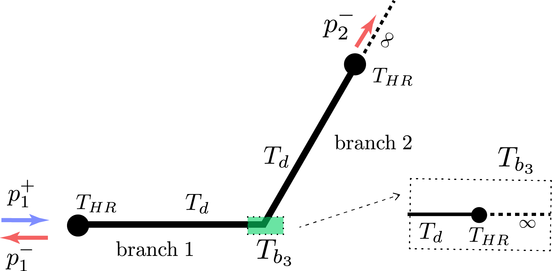
Eq. (13) is obtained by considering an incident wave from port 1 and assuming no backward waves for the two ports remaining (no input and anechoic end) as illustrated in the Fig. 4. Then by rearranging Eq. (13) we obtain the matrix elements of Eq. (12) as follows.
| (14) |
The elements of the matrix are explained in the following. The transfer matrix , corresponds to the HR loading the waveguide and is given by
| (15) |
where is the entrance admittance of the HR considered as a point scatterer. The expression for the admittance can be found for example in Ref[14], where detailed information about the viscothermal losses are also included. is the transfer matrix for the propagation along the waveguide of length and is given by
| (16) |
where is the wavenumber and is the characteristic impedance of the waveguide of cross-section . describes the influence of the third branch of the network (see Fig.4), and takes the following form
| (17) |
where is the entrance admittance of the branch 3 given by
| (18) |
In our calculations we consider the effect of losses in the waveguide and in the HRs using the Zwikker and Kosten model[52] which includes an imaginary part in the wavenumber and in the characteristic impedances of the waveguides.
Optimization
From Eq. 14, we obtain the reflexion and transmission coefficients as a function of all the system’s geometrical parameters i.e. (see Fig. 1) and of the operating frequency . In order to find the device achieving both CPA and CPT, the reflexion and transmission coefficients should satisfy Eq. (6) [(7)] with the additional constraints []. To obtain solutions satisfying this condition, a numerical optimization based on simplex derivative free method Nelder-Mead [53] with 6 optimization parameters (fixing the operating frequency) under experimentally and physically reasonable constraints is used.
References
- [1] E. Cubukcu, S. Zhang, Y-S. Park, G. Bartal and X. Zhang, Split ring resonator sensors for infrared detection of single molecular monolayers, Appl. Phys. Lett. 95, 043113 (2009); doi: 10.1063/1.3194154.
- [2] H-J. Lee and J-G. Yook, Biosensing using split-ring resonators at microwave regime, Appl. Phys. Lett. 92, 254103 (2008); doi: 10.1063/1.2946656.
- [3] P. Yu, J. Wu, E. Ashalley, A. Govorov and Z. Wang, J. Phys. D: Appl. Phys. 49 365101 (2016); doi:10.1088/0022-3727/49/36/365101.
- [4] J. Mei, G. Ma, M. Yang, Z. Yang, We. Wen and P. Sheng, ”Dark acoustic metamaterials as super absorbers for low-frequency sound”, Nature communication, 3, 756, 2012, doi:10.1038/ncomms1758.
- [5] M. Yang, S. Chen, C. Fu, P. Sheng, Optimal sound absorbing structures, Mater. Horiz. 4, 673-680 (2017); doi:10.1039/C7MH00129K
- [6] H. Ramezani, Y. Wang, E. Yablonovitch, X.Zhang, Unidirectional Perfect Absorber, IEEE Journal of Selected Topics in Quantum Electronics, 22, 5 (2016).
- [7] S. Longhi, PT-symmetric laser absorber, Phys. Rev. A 82, 031801(R) (2010)
- [8] Y. D. Chong, L. Ge, H. Cao and A. D. Stone, Coherent perfect absorbers: time-reversed lasers, Phys. Rev. Lett., 105, 053901 (2010); doi: 10.1103/PhysRevLett.105.053901.
- [9] Y. Sun, W. Tan, H. Li, J. Li and H. Chen, Experimental Demonstration of a Coherent Perfect Absorber with PT Phase Transition, Phys. Rev. Lett., 112, 143903 (2014); doi: 10.1103/PhysRevLett.112.143903.
- [10] S. Zanotto, F. Bianco, V. Miseikis, D. Convertino and C. Coletti, Coherent absorption of light by graphene and other optically conducting surfaces in realistic on-substrate configurations, APL Photonics, 2, 016101 (2017); doi: 10.1063/1.4967802.
- [11] S. Zanotto and A. Tredicucci, Universal lineshapes at the crossover between weak and strong critical coupling in Fano-resonant coupled oscillators, Sci. Rep. 6, 24592 (2016); doi: 10.1038/srep24592, 2016.
- [12] L. Zhu, J. Guo, L.Dong, F-Y. Meng and Q.Wu, Coherent perfect absorption in an electromagnetically induced transparency- like (EIT-like) system, J. Opt. 18, 095104 (2016); doi:10.1088/2040-8978/18/9/095104.
- [13] L. Baldacci, S. Zanotto, G. Biasiol, L. Sorba and A. Tredicucci, Interferometric control of absorption in thin plasmonic metamaterials: general two port theory and broadband operation, Opt. Express 23, 9202-9210 (2015);
- [14] A. Merkel, G. Theocharis, O. Richoux, V. Romero-Garcia and V. Pagneux, Control of acoustic absorption in 1D scattering by indirect coupled resonant scatterers, Appl. Phys. Lett. 107, 244102 (2015); doi: 10.1063/1.4938121.
- [15] C. Meng, X. Zhang, S.T. Tang, M. Yang and Z. Yang, Acoustic Coherent Perfect Absorbers as Sensitive Null Detectors, Sci. Rep. 7, 43574 (2017); doi: 10.1038/srep43574
- [16] J. Li, W. Wang, Y. Xie, B-I. Popa and S.A. Cummer, A sound absorbing metasurface with coupled resonators, Appl. Phys. Lett. 109, 091908 (2016); doi: 10.1063/1.4961671
- [17] Y. Xu, Y. Li, R. K. Lee, and A. Yariv, Scattering-theory analysis of waveguide-resonator coupling, Phys. Rev. E 62, 7389 (2000).
- [18] G. Ma, M. Yang, S. Xiao, Z. Yang, and P. Sheng, Acoustic metasurface with hybrid resonances, Nat. Mater. 13, 873 (2014), DOI: 10.1038/NMAT3994.
- [19] P. Wei, C. Croenne, S. Chu, and J. Li, Symmetrical and anti-symmetrical coherent perfect absorption for acoustic waves, Appl. Phys. Lett. 104, 121902 (2014).
- [20] H. Long, Y. Cheng, J. Tao and X. Liu, Perfect absorption of low-frequency sound waves by critically coupled subwavelength resonant system, Appl. Phys. Lett. 110, 023502 (2017);
- [21] V. Romero-Garcia, G. Theocharis, O. Richoux, A. Merkel and V. Tournat, and V. Pagneux, Perfect and broadband acoustic absorption by critically coupled sub-wavelength resonators, Sci. Rep. 6, 19519 (2016).
- [22] Y. Li and B.M. Assouar, Acoustic metasurface-based perfect absorber with deep subwavelength thickness, Appl. Phys. Lett. 108, 063502 (2016), doi : 10.1063/1.4941338
- [23] X. Cai, Q. Guo, G. Huand J.Yang, Ultrathin low-frequency sound absorbing panels based on coplanar spiral tubes or coplanar Helmholtz resonators, Appl. Phys. Lett. 105, 121901 (2014); doi: 10.1063/1.4895617
- [24] X. Jiang, B. Liang, R. Li, X. Zou, L. Yin and J. Cheng, Ultra-broadband absorption by acoustic metamaterials, Appl. Phys. Lett. 105, 243505 (2014); doi: 10.1063/1.4904887.
- [25] J.-P. Groby, W. Huang, A. Lardeau, and Y. Auregan, The use of slow sound to design simple sound absorbing materials, J. Appl. Phys. 117, 124903 (2015).
- [26] J.-P. Groby, R. Pommier, and Y. Auregan, Use of slow sound to design perfect and broadband sound absorbing materials, J. Acoust. Soc. Am. 139, 1660 (2016).
- [27] J. Yang, J.S. Lee, H.R. Lee, Y.J. Kang and Y.Y. Kim, Slow-wave metamaterial open panels for efficient reduction of low-frequency sound transmission, Appl. Phys. Lett. 112, 091901 (2018);
- [28] V. Romero-Garcia, G. Theocharis, O. Richoux and V. Pagneux, Use of complex frequency plane to design broadband and sub-wavelength absorbers, J. Acoust. Soc. Am. 139, 3395 (2016).
- [29] N. Jiménez, W. Huang, V. Romero-García, V. Pagneux, J-P Groby, Ultra-thin metamaterial for perfect and quasi-omnidirectional sound absorption, Appl. Phys. Lett. 109, 121902 (2016).
- [30] V. Achilleos, O. Richoux and G. Theocharis, Coherent perfect absorption induced by the nonlinearity of a Helmholtz resonator, J. Acoust. Soc. Am. 140, 94 (2016).
- [31] M. Gil, J. Bonache, I. Gil, J. García-García and F. Martín, Miniaturisation of planar microwave circuits by using resonant-type left-handed transmission lines, IET Microw. Antennas Propag. 1(1), pp. 73–79 (2007).
- [32] X. Shang, Y. Wang, W. Xia, and Michael J. Lancaster, Novel Multiplexer Topologies Based on All-Resonator Structures, IEEE TRANSACTIONS ON MICROWAVE THEORY AND TECHNIQUES 61, NO. 11 (2013)
- [33] P. Aleahmad, M. Khajavikhan, D. Christodoulides and P. LiKamWa, Integrated multi-port circulators for unidirectional optical information transport, Sci. Rep., 7, 2129 (2017); doi:10.1038/s41598-017-02340-9.
- [34] D. Pan, H. Wei and H. Xu, Optical interferometric logic gates based on metal slot waveguide network realizing whole fundamental logic operations, Opt. Express 21, 9556-9562 (2013); doi:10.1364/OE.21.009556
- [35] G. Veronis and S. Fan, Bends and splitters in metal-dielectric-metal subwavelength plasmonic waveguides, Appl. Phys. Lett. 87, 131102 (2005); doi: 10.1063/1.2056594.
- [36] E. Feigenbaum and M. Orenstein, Perfect 4-way splitting in nano plasmonic X-junctions, Opt. Express 15(26), 17948–17953 (2007).
- [37] E. Feigenbaum and H. A. Atwater, Resonant guided wave networks, Phys. Rev. Lett. 104(14), 147402 (2010).
- [38] E. Feigenbaum, S. P. Burgos and H. A. Atwater, Synthesis and Characterization of Plasmonic Resonant Guided Wave Networks, Nano Lett., 14(6), 3284–3292 (2014); doi:10.1021/nl500694c.
- [39] T. Roger et al., Coherent perfect absorption in deeply subwavelength films in the single-photon regime, Nat. com., 6, 7031 (2015); doi:10.1038/ncomms803.
- [40] G.B. Akguc, L.E. Reichl, A. Shaji and M.G. Snyder, Bell states in a resonant quantum waveguide network, Phys. Rev. A 69, 042303 (2004); doi: 10.1103/PhysRevA.69.042303.
- [41] M. Molerón, G. Dubois, O. Richoux, S Félix and V. Pagneux, Reduced Modal Modelling of Time-Domain Propagation in Complex Waveguide Networks, Acta Acustica, 100, 391-400 (2014); doi:10.3813/AAA.918718.
- [42] S. Zhang, L. Yin and N. Fang, Focusing Ultrasound with an Acoustic Metamaterial Network, Phys. Rev. Lett., 102, 194301 (2009).
- [43] Q. Wei, Y. Tian, S-Y. Zuo, Y. Cheng and X-J. Liu, Experimental demonstration of topologically protected efficient sound propagation in an acoustic waveguide network, Phys. Rev. B, 95, 094305 (2017).
- [44] Y-G. Peng, Y-X. Shen, D-G. Zhao, and X-F. Zhu, Low-loss and broadband anomalous Floquet topological insulator for airborne sound, Appl. Phys. Lett, 110, 173505 (2017).
- [45] X. Zhang,C. Meng and Z.Yang, Wave Manipulations by Coherent Perfect Channeling, Sci. Rep., 7, 13907 (2017); doi:10.1038/s41598-017-14422-9.
- [46] Y. Fu and Y. Xu, Asymmetric effects in waveguide systems using PT symmetry and zero index metamaterials, Sci. Rep., 7, 12476 (2017); doi:10.1038/s41598-017-12592-0.
- [47] H. Ramezani, M. Dubois, Y. Wang, Y.R. Shen and X. Zhang, Directional excitation without breaking reciprocity, New J. Phys. 18, 095001 (2016); doi:10.1088/1367-2630/18/9/095001.
- [48] B. H. Song and J. S. Bolton, A transfer-matrix approach for estimating the characteristic impedance and wave numbers of limp and rigid porous materials, J. Acoust. Soc. Am. 107, 1131–1152 (2000).
- [49] R. T. Muehleisen and C. W. Beamer IV, Comparison of errors in the three- and four-microphone methods used in the measurement of the acoustic properties of porous materials, ARLO 3(4), 112–117 (2002).
- [50] m, m, m, m, m and m.
- [51] m, m, m, m, m and m.
- [52] C. Zwikker and C. Kosten, Sound absorbing materials (Elsevier Publishing Company, Inc., Amsterdam, 1949).
- [53] J. C. Lagarias, J. A. Reeds, M. H. Wright and P. E. Wright, Convergence Properties of the Nelder-Mead Simplex Method in Low Dimensions,SIAM Journal of Optimization. 9(1), 112–147 (1998).
Acknowledgements
This work is supported by ”Le Mans Acoustique” and funded by the ”Pays de la Loire” French Region ” and the ”European Regional Development Fund”. I. Brouzos appreciates financial support from IKY (State Scholarships Foundation).
Author contributions
O.R., V.A. and G.T. performed the theoretical simulations; I.B. performed the optimization process. O.R. and V.A. performed the experiments; O.R., V.A., G.T. and I.B. wrote the manuscript. All authors contributed to data analysis and discussions.
Additional Information
Competing Interests: the authors declare that they have no competing interests.