Breaking the energy-symmetry blockade in magneto-optical rotation
Abstract
The magneto-optical polarization rotation effect has prolific applications in various research areas spanning the scientific spectrum including space and interstellar research, nano-technology and material science, biomedical imaging, and sub-atomic particle research. In nonlinear magneto-optical rotation (NMOR), the intensity of a linearly-polarized probe field affects the rotation of its own polarization plane while propagating in a magnetized medium. However, typical NMOR signals of conventional single-beam scheme atomic magnetometers are peculiarly small, requiring sophisticated magnetic shielding under complex operational conditions. Here, we show the presence of an energy-symmetry blockade that undermines the NMOR effect in conventional single-beam scheme atomic magnetometers. We further demonstrate, both experimentally and theoretically, an inelastic wave-mixing technique that breaks this NMOR blockade, resulting in more than five orders of magnitude (300,000-fold) NMOR optical signal power spectral density enhancement never before seen with conventional single-beam scheme atomic magnetometers. This new technique, demonstrated with substantially reduced light intensities, may lead to many applications, especially in the field of bio-magnetism and high-resolution low-field magnetic imaging.
Magneto-optical effects arise when the different polarized components of an electrical field resonantly coupling to magnetic transitions of an atom experience different magnetic dichriosm r1 ; r1b ; r1c . When the effects become dependent on the intensity of the electric field itself, the resulting rotation of the polarization plane of the field is referred to as nonlinear magneto-optical rotation (NMOR). All polarimetry-based alkali metal vapor atomic magnetometers employ this principle for extremely weak magnetic field detection. Using spin relaxation management techniques r2 ; r3 ; r4 ; r5 ; r6 ; r7 ; r8 ; r9 ; r10 ; r11 , together with state-of-the-art magnetic shieldings and phase-locking detection electronics, atomic magnetometers have demonstrated extremely high sensitivities r6 ; r8 ; r9 ; r10 ; r11 ; r12 ; r12a approaching the benchmark performance of superconducting quantum interference devices r12b .
The core element of polarimetry-based alkali vapor atomic magnetometers is a three-state atomic system [Fig. 1(a)]
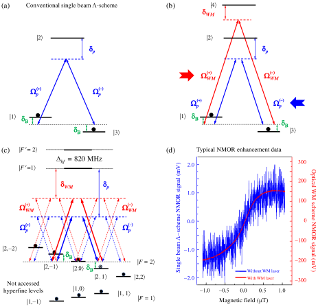
coupling to a linearly polarized probe field r13 ; r14 ; r15 ; r15a ; r15b ; r15c . Although the NMOR signal is enhanced by the probe intensity in this simple -scheme, the NMOR optical signal-to-noise ratio (SNR) is generally low, requiring complex magnetic shielding and sophisticated electronics in addition to long data-acquisition times. Here, we introduce an optical inelastic wave-mixing (WM) process via a second light field counter-propagating with respect to the probe field. This inelastic WM process opens a multi-excitation channel by sharing two fully-occupied intermediate states r17 ; r17a ; r18 with the probe field. Consequently, it significantly modifies the ground-state Zeeman coherence and the magnetic dichroism at the probe frequency. The key underlying physics of this new technique is the removal of the energy-symmetry-based NMOR blockade inherent in conventional single-beam type atomic magnetometers, unleashing the full propagation strength of the NMOR effect and giving rise to more than five orders of magnitude NMOR optical signal power spectral density SNR enhancement.
Theoretical framework. Consider the simplified four-state atomic system, depicted in Fig. 1(b), where atomic state has energy (). We assume that the probe field (frequency ) is polarized along the -axis and propagates along the -axis. Its components couple independently the and transitions with a large one-photon detuning , forming two-photon transitions between states with a two-photon detuning . Here, the Zeeman frequency shift in the axial magnetic field referenced to the mid-point, i.e., the state, between the two equally but oppositely shifted Zeeman levels and (see Figs. 1a and 1b). An optical WM field (frequency ) propagates along the -axis but has its linear polarization making an angle with respect to the -axis. Its components independently couple the and transitions with a large one-photon detuning , forming two-photon transitions between states with the same two-photon detuning . Therefore, we have two transitions that share the same equally-populated states and , creating a mutually influencing ground-state Zeeman coherence. We note that this is very different from the conventional double-Lambda four wave mixing process r18 ; r18a ; r18b ; r18c ; r18d where the intermediate state has negligible Zeeman coherence [see discussion on Fig. S3].
The total electric field is given as where in general, and . Here, , , and is the wavevector of the probe (WM) field. Expressing the electric field in a rotating basis using the relation and with being the unit vectors in the rotation bases, we then have with and with .
Under the electric-dipole and the rotating-wave approximations, the interaction Hamiltonian of the system in the interaction picture can be expressed as
| (1) |
where is the laser detuning from state . Here, the half-Rabi frequencies of the probe field are and . The half-Rabi frequencies of the WM field are and because it counter-propagates with respect to the magnetic field direction. is the transition matrix element of the dipole operator .
The dynamic behavior of the atomic system can be obtained by solving the Liouville equation given by
| (2) |
where is the density matrix operator of the atomic system. with and being the collisional (the Zeeman ground states) and radiative (the excited electronic states) decay rates, respectively.
Under the slowly varying envelope approximation, the Maxwell equations describing the evolution of the probe and WM fields are given as
| (3a) | |||
| (3b) | |||
where with , , and being the atom number density, vacuum permittivity, and speed of light in vacuum, respectively. Equations (1-3), which include 16 equations of motion for density matrix elements and 4 Maxwell equations for all circularly-polarized components of the two electrical fields, can be solved numerically to yield the probe-field dynamics from which all magneto-optical parameters can be evaluated.
Enhancement of NMOR optical SNR: Physical intuition. Intuitive understanding of the large NMOR optical SNR enhancement and Zeeman coherence evolution can be gained by considering the steady-state solutions of Eq. (2) in the thin-medium limit. This approximation applies in the region near the entrance where changes in the probe field are not significant and a perturbation treatment for the NMOR signal is valid (see Methods). To this end, we assume that initially all atoms have their population shared equally between the states and , but there is no appreciable initial Zeeman coherence r19 .
In the thin-medium limit, the probe NMOR effect can be expressed perturbatively as [see Eq. (5) in Methods],
where the superscript indicates the perturbation order and
Here, is the NMOR of the conventional single-beam scheme [blue arrows in Fig. 1(b)] and is the contribution to the total probe NMOR arising from the WM field [red arrows in Fig. 1(b)]. This WM contribution has more profound physical consequences than just a simple additional polarization source term for the electrical fields. First, notice that the terms in the square bracket in have the identical Zeeman frequency shift denominators as that in , and this implies it has an identical magnetic resonance line shape, a critical magnetic-field-sensitivity-preserving feature of the optical WM method.
From a nonlinear optics point of view, because the Zeeman states and are initially equally populated there are two competing two-photon processes that drive the population transfer and establish the ground-state Zeeman coherence in the conventional single-beam scheme [Fig. 1(a)]. The two-photon transition requires the absorption of photons followed by emission of photons and the two-photon transition requires absorption of photons followed by emission of photons. Since the probe field is the only source of energy, the symmetric nature of these two two-photon processes dictates that both probe polarization components cannot change appreciably, resulting in r19a
where is the medium length. This energy-symmetry blockade is the primary reason why the source term for the probe field, having a third-order nonlinearity, results in a NMOR angle rotation that is only linearly proportional to the atom density and medium length. It is this energy-symmetry blockade that suppresses the full non-linear propagation strength of the NMOR effect in single-beam type magnetometry. The WM field in the WM scheme (Fig. 1b) introduces an inelastic WM and scattering process (see Fig. S3 in Supplementary Material) that allows coherent energy transfer from the WM field to both the probe field and atomic medium, breaking the probe energy-symmetry blockade and enabling nonlinear growth of the probe polarization components. The result is the unprecedented NMOR optical SNR enhancement [see Fig. 1(d)].
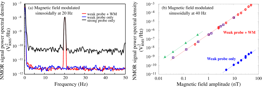
Figure 2 further demonstrates the exceptionally low noise performance, large dynamic range, and more than 300,000-fold NMOR optical signal power spectral density enhancement using the inelastic WM technique. In Fig. 2(a), we show the NMOR optical signal power spectral density using a magnetic field of 10 nT modulated sinusoidally at 20 Hz. We first chose a very weak probe field so that no NMOR signal can be observed when the WM field was absent (blue trace). When the WM field was turned on a huge NMOR signal was observed (red peak). However, the noise in the red trace is at the same level as that of the blue trace, indicating no appreciable additional noise was added, even though more than a 3 order of magnitude NMOR signal optical power spectral density enhancement was achieved. We then switched off the WM field and increased the probe intensity to match the NMOR signal amplitude set by the WM field. This single-beam technique requires a substantially higher probe field intensity and as a result it exhibits a nearly two order of magnitude higher noise level (Fig. 2(a), black traces). Figure 2(b) illustrates an even more astonishing NMOR optical power spectral density enhancement with a large magneto-optical dynamic range response. Here, we plot the NMOR signal peak value as a function of the magnetic field amplitude. The greater-than 300,000-fold optical signal power spectral density enhancement over the conventional single-beam technique demonstrates the superior performance and robustness of the optical WM technique. We emphasize that the data shown in Fig. 2b exhibit perfect linearity with an identical slope for both the optical WM technique and the single beam technique. This indicates that the optical WM technique can reach the same detection sensitivity of current state-of-the-art single beam transition-based technologies under the same near zero-field conditions at ambient temperature, but with a more than 10fold enhancement in the NMOR optical signal power spectral density.
Another interesting feature introduced by the WM field can also be argued intuitively. When the linear polarization of the WM field makes an angle with respect to the linear polarization of the probe field, its Rabi frequencies acquire dependence in the basis because of the projection of the WM field. As a result, and in together contribute a factor of sin(2) in . Therefore, the contribution is maximized at the cross-polarization angle r1b . At and , and the NMOR effect is negligible precisely because of the probe energy-symmetry NMOR blockade described above.
Enhancement of NMOR optical SNR: Numerical calculations. To obtain full probe-field polarization dynamics, we numerically integrated 16 atomic density matrix equations and 4 Maxwell equations (see Methods for all calculation parameters).
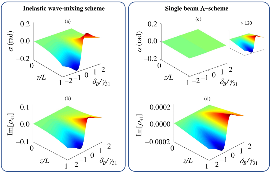
In Fig. 3 we show the probe NMOR angle and the ground-state Zeeman coherence Im[] which is responsible to the growth of as functions of the normalized Zeeman frequency and propagating distance . Here, we have taken as discussed above [the effect of this angle is discussed in Fig. 4(a) and 4(b)]. Two of the most noticeable features shown in Fig. 3 are: (1) the NMOR rotation by the optical WM technique [Fig. 3(a)] is more than 100 times larger than that of the conventional single beam technique [Fig. 3(c)], confirming our experimental observations shown in Fig. 1(d); and (2) the NMOR line shape of the optical WM technique is identical to that of the single beam technique [see the inset in Fig. 3(c)] which also agrees with experimental observations [see Fig. 1(d)]. This latter feature is critically important in applications since the resonance line shape determines the detection resolution and sensitivity for magnetic field detection.
The ground-state Zeeman coherence is of central importance to magneto-optical effects arising from ground-state magnetic dichroism. In the conventional single beam scheme, the NMOR-blockade restricts the growth of ground-state Zeeman coherence, limiting the growth of the NMOR effect [Fig. 3(d)]. The removal of this NMOR propagation blockade by the optical WM method enables significant ground-state Zeeman coherence growth [Fig. 3(b)] by efficient inelastic scattering (see discussion of Fig. S3 in Supplementary Material), resulting in a highly efficient NMOR optical SNR enhancement. The significant difference in Im[] attests to the fundamental difference between the two schemes. Indeed, it is quite astonishing that such a weak, symmetry-breaking WM field can lead to such a significant increase in the system’s Zeeman coherence.
In the calculations above we chose the cross-polarization angle between the two fields as . In the inelastic optical WM method the probe polarization rotation is strongly dependent on this angle.
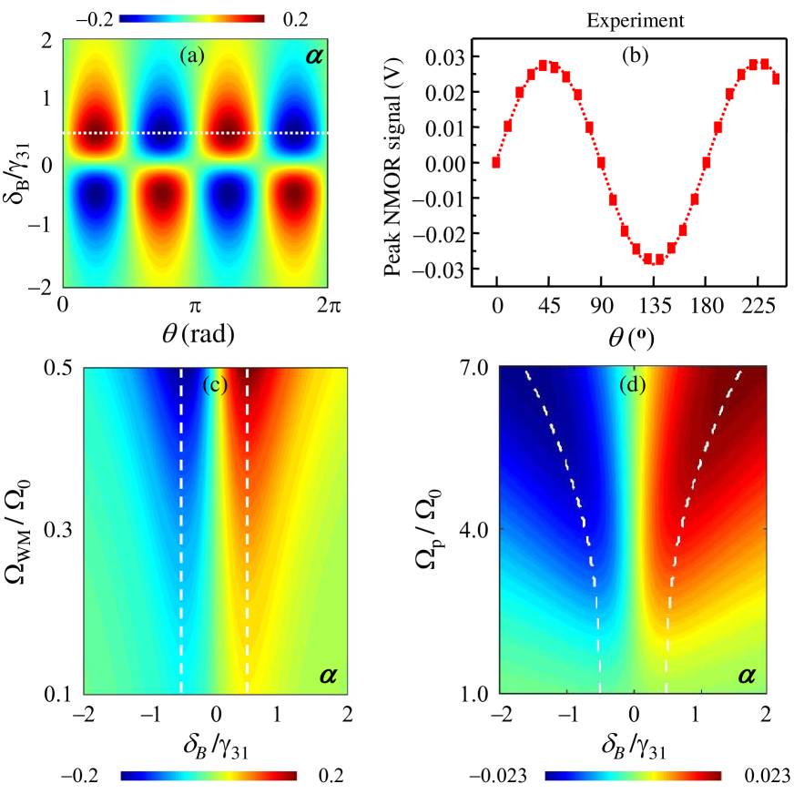
In Fig. 4(a) we show the probe NMOR as a function of the and . Experimentally, we set a constant magnetic field and varied the angle between the linear polarizations of the two fields. When this cross-polarization angle , the NMOR optical SNR enhancement is maximized [Fig. 4(b)], in a full agreement with numerical calculations.
One of the advantages of the inelastic optical WM method is that the large NMOR optical SNR enhancement is achieved simultaneously with substantially reduced probe field intensities (the WM field intensity is even lower). This has a significant technological advantage in applications. In the conventional single-beam method, the probe intensity must be sufficiently high to bring out the NMOR effect (typically, more than 500 W/cm2 probe intensities are used with substantially smaller one-photon detunings). Using the WM method, we observed NMOR signals with only a probe intensity of 10 W/cm2, and with a one-photon detuning 10 times larger. Under these light-level conditions the conventional single-beam scheme yields no detectable signal, even with long data acquisition times. One immediate benefit of such a low-level optical power operation is the possibility of achieving an unprecedented magnetic field detection sensitivity using atomic species with Zeeman de-coherence rates of less than 1 Hz. Indeed, under the typical light intensity level, single-beam methods will introduce an intolerable power broadening r20 ; r21 that degrades the magnetic resonance line shape of ground-state Zeeman levels with such small de-coherence rates.
To demonstrate the advantage of the low light level NMOR effect using the optical WM method, we show in Fig. 4(c) the numerical calculation of the probe NMOR signal as a function of the normalized Zeeman shift frequency and the WM field Rabi frequency (here we fix 200 kHz). The white dashed lines indicates the peaks of the NMOR signal, showing the preserved magnetic resonance width. However, the calculated probe NMOR signal of the conventional single-beam scheme [Fig. 4(d)] exhibits substantial power broadening as the probe intensity increases. Notice that even with the probe field as strong as 1.4 MHz, where the magnetic resonance line width has doubled from power broadening, the corresponding NMOR signal strength is still nearly a factor of 10 smaller than that shown in Fig. 4(c) (see the color scales). This demonstrates that the conventional single beam method will encounter a significant difficulty when applied to very low magnetic field detection using an atomic species with a ground-state Zeeman de-coherence rate of 1 Hz.
We have shown, both experimentally and theoretically, an inelastic WM technique that removes the energy-symmetry-based NMOR blockade inherent in the widely-used conventional single-beam method and enables an unprecedented NMOR signal SNR. The principle and technique demonstrated in our work may also facilitate applications employing similar fundamental physical principles.
Acknowledgements.
CJZ acknowledge the National Key Basic Research Special Foundation (Grant No. 2016YFA0302800); the 973 Program (Grant No. 2013CB632701); the Joint Fund of the National Natural Science Foundation (Grant No. U1330203).References
- (1) A.K. Zvezdin and V.A. Kotov, Modern Magento-optics and Magneto-optical Materials. Taylor & Francis Group, New York (1997).
- (2) A. Weis, J. Wurster, and S. I. Kanorsky, Quantitative interpretation of the nonlinear Faraday effect as a Hanle effect of a light-induced birefringence, J. Opt. Soc. Am. B 10, 716-724 (1993).
- (3) S.I. Kanorsky, A. Weis, J. Wurster, and T.W. Hansch, Quantitative investigation of the resonant nonlinear Faraday effect under conditions of optical hyperfine pumping, Phys. Rev. A 47, 1220-1226 (1993).
- (4) W. Happer and A.C. Tam, Effect of rapid spin exchange on the magnetic-resonance spectrum of alkali vapors, Phys. Rev. A 16, 1877-1891 (1977).
- (5) C.J. Erickson, D. Levron, W. Happer, S. Kadlecek, B. Chann, L.W. Anderson, T.G. Walker, Spin Relaxation Resonances due to the Spin-Axis Interaction in Dense Rubidium and Cesium Vapor, Phys. Rev. Lett. 85, 4237-4240 (2000).
- (6) S. Kadlecek, L.W. Anderson, T.G. Walker, Field dependence of spin relaxation in a dense Rb vapor, Phys. Rev. Lett. 80, 5512-5515 (1998).
- (7) J.C. Allred, R.N. Lyman, T.W. Kornack, and M.V. Romalis, High-Sensitivity Atomic Magnetometer Unaffected by Spin-Exchange Relaxation, Phys. Rev. Lett. 89, 130801 1-4 (2002).
- (8) I.K. Kominis, T.W. Kornack, J.C. Allred, and M.V. Romalis, A subfemtotesla multichannel atomic magnetometer, Nature 422, 596-599 (2003).
- (9) I.M. Savukov and M.V. Romalis, Effects of spin-exchange collisions in a high-density alkali-metal vapor in low magnetic fields, Phys. Rev. A 71, 023405 1-8 (2005).
- (10) D. Budker, V. Yashchuk, and M. Zolotorev, Nonlinear magneto-optical effects with ultranarrow widths, Phys. Rev. Lett. 81, 5788-5791 (1998)
- (11) E.B. Aleksandrov et al., Laser pumping in the scheme of an Mx-magnetometer, Optics Spectrosc. 78, 292-298 (1995).
- (12) M.V. Balabas, T. Karaulanov, M.P. Ledbetter, and D. Budker, Polarized Alkali-Metal Vapor with Minute-Long Transverse Spin-Relaxation Time, Phys. Rev. Lett. 105, 070801 1-4 (2010).
- (13) A. Korver, R. Wyllie, B. Lancor, and T. G. Walker, Suppression of Spin-Exchange Relaxation Using Pulsed Parametric Resonance, Phys. Rev. Lett. 111, 043002 (2013).
- (14) D. Budker and M. Romalis, Optical Magnetometry, Nature Physics 3, 227-234 (2007).
- (15) W. Gawlik and S. Pustelny, Nonlinear Magneto-Optical Rotation Magnetometers, High Sensitivity Magnetometers, A. Grosz, M. J. Haji-sheikh, and S. C. Mukhopadhyay, Editors, Springer Series: Smart Sensors, Measurement and Instrumentation 19, 425-450, Springer International Publishing Switzerland 2017.
- (16) R. Kleiner, D. Koelle, F. Ludwig, J. Clarke, Superconducting quantum interference devices: State of the art and applications. Proceedings of the IEEE. 92, 1534-1548 (2004).
- (17) D. Budker and D.F.J. Kimball, Optical Magnetometry. Cambridge University Press (2013).
- (18) There are other transitions in a warm vapor that may contribute to the NMOR enhancement effect even when the non-accessed hyperfine states have been optically pumped. However, the simplified single beam scheme provides a simple but key understanding of the NMOR effect.
- (19) M. Auzinsh, D. Budker, and S. Rochester, Optically Polarized Atoms: Understanding light-atom interactions, Oxford University Press, New York (2010).
- (20) D. Budker, D.F. Kimball, S.M. Rochester, V.V. Yashchuk, and M. Zolotorev, Sensitive magnetometry based on nonlinear magneto-optical rotation, Phys. Rev. A 62, 043403 1-7 (2000).
- (21) A. B. Matsko, I. Novikova, M. S. Zubairy, and G. R. Welch, Nonlinear magneto-optical rotation of elliptically polarized light, Phys. Rev. A 67, 043805 – Published 11 April 2003.
- (22) D. Budker, W. Gawlik, D.F. Kimball, S.M. Rochester, V.V. Yashchuk, and A. Weis, Resonant nonlinear magneto-optical effects in atoms, Rev. Mod. Phys. 74, 1153 (2002).
- (23) L. Deng, M.G. Payne, W.R. Garrett, Inelastic four-wave mixing and multiple simultaneous interference based suppressions. Opt. Commun. 242, 641-647 (2004).
- (24) All pump-probe experiments, regardless of whether they employ saturated absorption spectroscopy or polarization spectroscopy, essentially rely on a two-level atomic system where both the pump and the probe are on resonance. The pump field saturates the transition while the probe is scanned across the absorption profile. In all these operations only the linearized response of the probe field is considered. Our system does not satisfy any of these conditions.
- (25) L. Deng, M.G. Payne, and W.R. Garrett, Effect of multi-photon interference from internally generated fields in strongly resonant systems, Phys. Reports 429, 123-241 (2006).
- (26) M.O. Scully and M. Fleischhauer, High-sensitivity magnetometer based on index-enhanced media, Phys. Rev. Lett. 69, 1360-1363 (1992).
- (27) P. Siddons, C.S. Adams, and I.G. Hughes, Optical control of Faraday rotation in hot Rb vapor, Phys. Rev. A 81, 043838 1-6 (2010).
- (28) Bo Wang, Shujing Li, Jie Ma, Hai Wang, K.C. Peng, and Min Xiao, Controlling polarization rotation of an optical field via asymmetry in electromagnetically induced transparency, Phys. Rev. A 73, 051801(R) (2006).
- (29) V.A. Sautenkov, M.D. Lukin, C.J. Bednar, I. Novikova, E. Mikhailov, M. Fleischhauer, V.L. Velichansky, G.R. Welch, and M.O. Scully, Enhancement of magneto-optic effects via large atomic coherence in optically dense media, Phys. Rev. A 62, 023810 1-4, (2000).
- (30) This corresponds to thermally distributed populations when the two states are degenerate or nearly degenerate (neglecting vacuum induced spontaneous coherence).
- (31) In the thin medium limit all probe Rabi frequencies appear in , which is the polarization source for the probe Maxwell equations, are constant, i.e., . This leads to r15 .
- (32) J.F. Ward and A.V. Smith, Saturation of two-photon resonant optical processes in Cs vapor. Phys. Rev. Lett. 35, 653-656 (1975).
- (33) E.B. Alexandrov, M.V. Balabas, A.S. Pasgalev, A.K. Vershovskii, and N.N. Yakobson, Double-resonance atomic magnetometers: from gas discharge to laser pumping. Laser Physics 6, 244-251 (1996).
- (34) G.P. Agrawal, Nonlinear Fiber Optics, Chapter 7, Academic Press, San Diego, CA (2001).