Offline and Online calibration of Mobile Robot and SLAM Device for Navigation
Abstract
Robot navigation technology is required to accomplish difficult tasks in various environments. In navigation, it is necessary to know the information of the external environments and the state of the robot under the environment. On the other hand, various studies have been done on SLAM technology, which is also used for navigation, but also applied to devices for Mixed Reality and the like.
In this paper, we propose a robot-device calibration method for navigation with a device using SLAM technology on a robot. The calibration is performed by using the position and orientation information given by the robot and the device. In the calibration, the most efficient way of movement is clarified according to the restriction of the robot movement. Furthermore, we also show a method to dynamically correct the position and orientation of the robot so that the information of the external environment and the shape information of the robot maintain consistency in order to reduce the dynamic error occurring during navigation.
Our method can be easily used for various kinds of robots and localization with sufficient precision for navigation is possible with offline calibration and online position correction. In the experiments, we confirm the parameters obtained by two types of offline calibration according to the degree of freedom of robot movement and validate the effectiveness of online correction method by plotting localized position error during robot’s intense movement. Finally, we show the demonstration of navigation using SLAM device.
I Introduction
Terrestrial mobile robots such as industrial AGV and home robot have been more popular and practical in various scenes. These robots are required to perform tasks autonomously on behalf of humans in flatten floor or ground. Robot navigation is a very important technique for the automatic execution of many tasks. Navigation requires information on the external environment and position and orientation of the robot in the environment.
There is a method of localizing a robot on an environment map of a place in where the robot is navigated prepared in advance. Various algorithms are used to localize robot such as ICP algorithm [1], 2D Monte Carlo Localization (MCL) [2], 3D MCL, A vision-based approach [3], RGB-D camera and particle filter [4]. For estimating position and orientation, some kinds of landmarks such as RFID (Radio-frequency identifier) [5] and two-dimensional bar code [6] are also used.
Meanwhile, SLAM (Simultaneous Localization and Mapping) technology using various kinds of sensor such as monocular camera [7, 8] and RGB-D camera [9] has been developed recently. SLAM-based navigation methods using various sensors such as laser range finder [10, 11] and RBG-D camera [12, 13] are also proposed. SLAM is also applied to devices for Augmented Reality (AR) and Mixed Reality (MR) such as a head-mounted display.
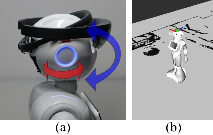
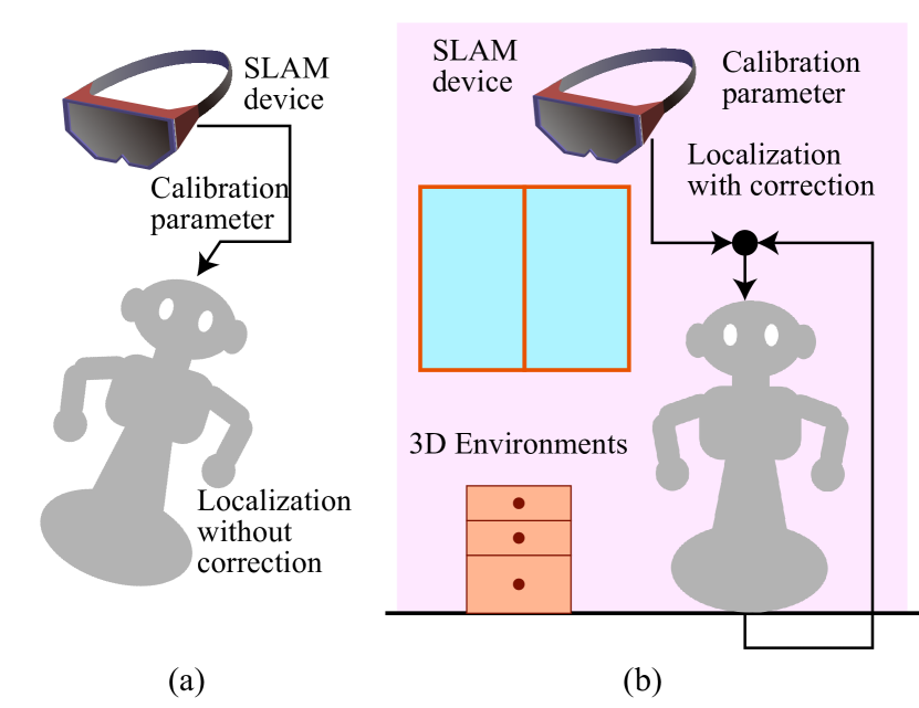
We refer to a real-time three-dimensional sensing device as ”SLAM device”. The SLAM device has the functions of sensing, mapping external environment and estimating the self position and pose in real time. MR applications require this functions to display virtual objects in a fixed position even when the device moves. In this research, we deal with robot-SLAM device calibration to navigate robot by using SLAM function of SLAM device as shown in Fig. 1 (a).
The aim of our research is robot-sensor extrinsic calibration. This calibration is necessary because the robot itself knows only the internal state and have to know the position and orientation in the environment through the SLAM device. Calibration between camera and robot arm is well known as hand-eye calibration. In [14, 15], a mathematical solution of the equation is shown. Fassi, et al. similarly discuss the solution of from a geometrical point of view [16]. Calibration methods of camera and IMU using the Kalman filter are also proposed in [17, 18]. However, these studies have not considered a restriction on freedom of the robot movements.
Some kinds of robot traveling ground have a restriction of movement. For example, a rover does not have a vertical rotation function. Completing calibration requires to know what parameters derived from a certain motion. Another problem is that dynamic errors may occur during navigation due to the shift of the device attached to the robot or the time lag of the encoders when joints of the robot moves. These errors can cause large localization error.
In this paper, we clarify the necessary movement and information for the calibration and show the most efficient calibration method with respect to the degree of freedom of the robot movement. The aim of this system is to apply SLAM system to various types of robots including a robot having such a restriction on freedom of their movement that normal hand-eye calibration methods do not consider. We deal with two cases: a case where the robot can rotate in two directions, a horizontal direction and a vertical direction, and a case where the robot can rotate in the horizontal direction but cannot rotate in the vertical direction, and show the optimal calibration method for each case. In the latter case, a calibration parameter that cannot be obtained from position and pose transition is acquired by using the position information of the SLAM device as supplementary information.
In addition to this offline calibration, we propose an online position correction method by adjusting the relative position and orientation of the robot and the device so that the consistency of the device-robot-external environment information holds. For example, the footprint pose of robot should be localized to be perpendicular to the floor. The rotation component of the calibration parameter is adjusted dynamically during robot moving to alleviate this localization error under the premise that the robot stands vertically and a vector perpendicular to the floor and a vector perpendicular to the ground plane of the robot coincide with each other.
II Problem Setting and Notation
The problem to solve in this calibration is to calculate relative rotation and translation parameters between ”head” and ”sd”. To solve this problem, we use each self-position estimated by robot and SLAM device as inputs and position and orientation transitions of the SLAM device and robot are calculated respectively. The robot has the IMU and motor encoder etc. and it is assumed that the position and pose parameter of the robot is given. In the SLAM device, it is assumed that external information can be acquired and its own position and pose in the world coordinate system is given. Robot shape information and 3-D map of external environment obtained by SLAM device is also used for offline and online calibration.
In our system, several coordinate systems are used: ”map” coordinate system, ”sd” coordinate system of SLAM device, ”head” coordinate system of the robot frame that SLAM device mounted on, and ”foot” coordinate system of the part of the robot contacting the floor. For convenience, the coordinate system of the robot frame to which the SLAM device is attached is called ”head”, but even if there is no head mechanism like the rover, this method can be used.
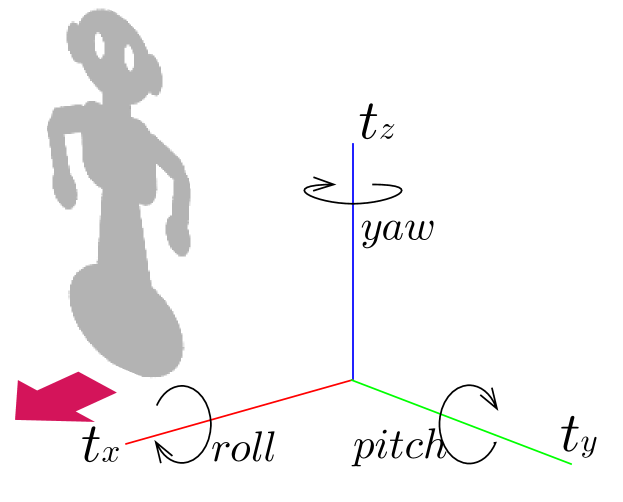
We deal with the parameters of 6-DoF of an unknown rotational and translational parameter. As shown in Fig. 2, we set the propulsion direction when the robot moves forward as and the vertical direction of the robot as . , , is translation parameter along the axis , , and , , is rotation parameter around the axis , , respectively.
III Analysis of Robot-Sensor Calibration from Transitions
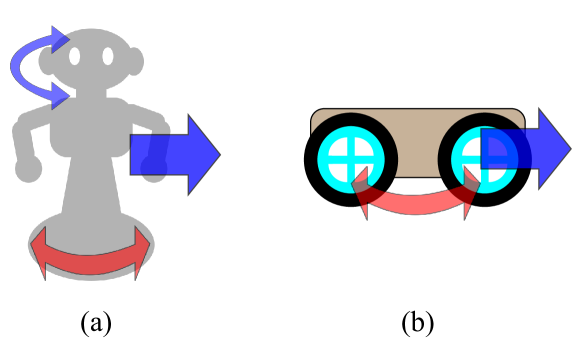
We analyze what parameters can be obtained from a certain motion. In contrast to normal hand-eye calibration, there is a possibility that the robot’s motion may be restricted depending on the robot to be used. For example, as shown in Fig. 5, a robot such as a humanoid type can swing the neck vertically and horizontally in addition to position movement. On the other hand, a robot like a rover type can not rotate in the longitudinal direction. We describe an optimal calibration method according to such degrees of freedom of movement.
III-A Obtaining pose transition
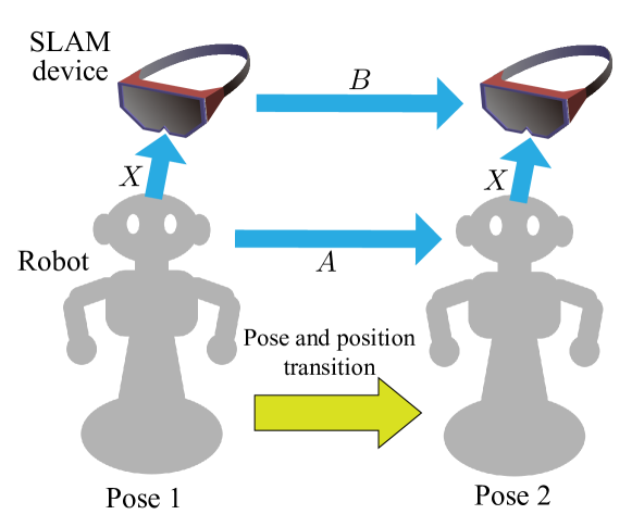
First, we explain the method to compute transition of robot and SLAM device for calculating the calibration parameters. In order to obtain the relative position and orientation between the robot and the SLAM device, the position and orientation transition is made and the differences between the two position and orientation parameters before and after the transition are taken. Let pose 1 be the initial posture of the head and the SLAM device and let pose 2 be their poses after the transition. Let and be matrix representing the position and pose in the local coordinates of each robot and SLAM device at pose 1 respectively. and be position and pose matrix in the local coordinates at pose 2 respectively. These matrices are the observed values. The differences between the two position and pose before and after the transition are given by the following equation,
| (1) | |||||
| (2) |
indicates transformation of the head from pose 1 to pose 2, and represents transformation of the SLAM device. Let be an unknown matrix representing the relative position and orientation between the robot and sensor given by the following equation,
| (5) |
As shown in Fig. 3, considering transformation from the coordinate frame of ”head” at pose 1 to the coordinate frame of ”sd” at pose 2, there are two transformations via ”head” at pose 2 and via ”sd” at pose 1. The former is represented by matrix calculation and the latter is represented by . The results are same in both coordinate transformations, therefore holds.
III-B Relation between movement and solved parameter
We describe the parameters obtained by the transitions. We mainly consider three types of movement of horizontal rotation, vertical rotation, forward movements and discuss what parameters can be derive from each motion based on solving in . The solution of is discussed in [14, 15, 16] and we can calculate by using linear and non-linear optimization from . Let and be rotation matrix components in and respectively, and be unit vectors indicating the rotation axis in and respectively. Let and be three-dimensional translation vector components. The following two formulas hold from [14],
| (6) | |||||
| (7) |
First of all, consider the constraint obtained from Eq. 6. Given a set of , , the 2-DoF rotational parameters other than around the vector among the 3-DoF rotation parameters included in are determined.
Subsequently, let us consider the constraints obtained from Eq. 7. Eq. 7 can be transformed as follows,
| (8) |
In Eq. 8, rank of is two. When rotating the robot and considering the case where is decomposed into components and two unit vectors and , which is orthogonal to and mutually orthogonal, in Eq. 8 has a degree of freedom in the direction and has constraints in the and directions since .
III-B1 Horizontal Rotation
When the robot rotates horizontally, rotational axis directs in the direction. In the case of rotation, in Eq. 6 directs the axis, and we can obtain the parameters , other than the rotation around the axis. In the case of translation parameters, constraints based on Eq. 8 are mainly applied to and .
III-B2 Vertical Rotation
In the case of performing a rotational motion in the vertical direction (here, it is assumed to rotate around the axis) such as swinging the neck vertically in the humanoid robot, similarly to horizontal rotation, two parameters of and can be obtained from Eq. 6. Translation parameter and is also obtained from Eq. 8.
III-B3 Forward Movement
When moving the robot straight (), Eq. 7 becomes as follows,
| (9) |
This equation is the same form as Eq. 6. Therefore constraint is applied to rotation parameters , when advancing the robot. Figure. 4 shows these relations between the position and pose transition method (horizontal rotation, vertical rotation, forward) and the restricted parameters.

IV Off-line robot-SLAM device calibration
We deal with two types of a robot: one is a robot that can rotate in two directions, the other is a robot that can move only in the horizontal direction ( direction, direction, rotation around axis in Fig. 2). The both are assumed to be capable of turn on the spot. In the former case, bi-directional rotation is optimal. In the later case, only five parameters can be obtained by horizontal rotation and forward movements. The remaining one is obtained using auxiliary information such as height of SLAM device.
IV-A Calibration using bi-directional rotation
We describe the conditions of position and orientation transition and the calibration method when the frame of a robot equipped with SLAM device can rotate in the vertical direction. We can see in Fig. 4 that the constraint is applied to , , , with horizontal rotation. For the remaining and , you can restrain these parameters by rotating in the vertical direction. Therefore, if horizontal rotation and vertical rotation are performed at least once, the constraint can be applied to all 6-DoF parameters.
IV-B Calibration using horizontal movement and SLAM device height
In the case of using a robot that is difficult to obtain . For the component in the remaining direction, we cannot constrain it by horizontal position and pose transition alone, therefore we use the height of the SLAM device from the floor to calculate the parameter. Let be the normal vector of the floor and be the height of the SLAM device from the floor. , can be observed from the environmental map of the SLAM device. Let be a vector from ”head” to ”foot”. It is known because robot’s shape information is available. Let be a parallel component to the floor of the vector from ”sd” to ”head”. indicates the shift of ”sd” and ”foot” in the plane parallel to floor.. It is perpendicular to defined by the following equation,
| (10) |
IV-C The case of a complex movement
Here, we consider a case where a complex position and pose transition including both rotation and translation at once is performed. From Eq. 8, is obtained using the difference between the translation component of the robot’s head and translational movement component of the SLAM device. Now, when rotating and translating at the same time in position and pose transition at once, accumulation error between odometry of the SLAM device and the robot occurs. This accumulation error is directly related to the error of calculated based on the difference between and . Therefore, in order to prevent this accumulation error and perform accurate calibration, it is necessary to minimize the robot translational movement (= length of ).
We consider whether there is superiority in terms of the minimum number of transitions necessary for calibration when performing position and pose transition including both rotation and translation at the same time. In Eq. 8, although constraints are applied to the three parameters , , , the rank of is two and one equation can bind only two parameters of the three. Therefore, even if a complex position and pose transition is performed, at least two transitions are required, as in the case of when using movements with only rotation and with only translation. For these reasons, it is better to use the only rotation movement and only translation movement so that the influence of accumulation error can be avoided.
V On-line position adjustment
We describe an online position correction method to correct relative position between the robot and the SLAM device so that the information of the external environment, the shape of the robot and the position of the device are consistent. Even if the calibration is performed offline in advance, there are several dynamic factors that make the location of the localized base incorrect during navigation. There is a possibility that the SLAM device may be misplaced while navigation is in operation. The accuracy of the IMU or the encoder of the robot causes an error, or the time lag of the encoder when the joint is moved also causes a large error. This makes robot be localized diagonally as shown in Fig. 6 (a). Therefore we adjust the robot’s pose so that the robot is properly grounded as shown in Fig. 6 (b).
Among the errors caused by these causes, in particular, errors in the axis and axis rotation lead to a large localization error when the device is mounted at a high position. In the online correction method, the parameters between the SLAM device and the robot are modified based on the premise that the robot stands perpendicular to the ground. The overview is shown in the Fig. 6. As a specific calculation, first, from the information of the external environment acquired by the SLAM device, find the normal vector of the floor and the vector perpendicular to the ground plane of the robot localized by the SLAM device before correction. Then apply additional correction rotation to the coordinate transformation between the robot and the device so that the two vectors match. This operation creates a partial loop closure that constrains two parameters and alleviates the localization error.
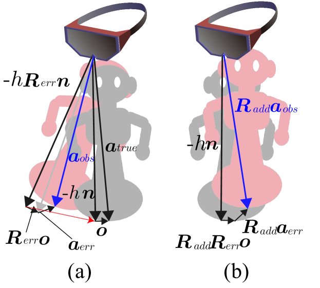
V-A Error analysis
We explain what factor become large localized error. A schematic diagram is shown in Fig. 7 (a). Let be the true value of the vector from the ”sd” coordinate center to the ”foot” coordinate center and be the observation value including translation and rotation error. Let and be the translational and rotational error factor. This error factor includes all the error in the transformations from ”sd” to ”foot” such as calibration error or robots encoder error. Using the translational error and the rotational error factor , is expressed as follows,
| (12) |
It is assumed that this error factor is caused by the above-mentioned deviation of the SLAM device and the error of the encoder. Next, decompose into a component in the direction of the unit vector perpendicular to the floor and a vector parallel to the floor and orthogonal to ,
| (13) |
where,
| (14) |
V-B Error correction
We explain how the error is reduced when applying an additional correction rotation. A schematic diagram is shown in Fig. 7 (b). Letting a vector perpendicular to the ground plane of the localized robot before correction be ,
| (16) |
Here the rotation matrix to rotate in the same direction as is decided, ie satisfies the following equation:
| (17) |
Integrating this correction matrix into the observation value ,
| (18) | |||||
where, we used that the following equation is established from Eq. 16 and Eq. 17
| (19) |
Comparing Eq. 13, Eq. 15, Eq. 18, we can see that the term of in Eq. 15, which was the cause of the error increase, was corrected and canceled in Eq. 13 and Eq. 18. Schematic diagram of this is shown in Fig. 7. This correction method cancels and , witch are the two degrees of freedom rotational parameters other than the rotation component around the vector of and removes the error component of localization proportional to the height of the robot.
When actually calculating , we can use the vector perpendicular to the ground plane of the localized robot before correction as the observed value of and the floor normal obtained from the SLAM device’s 3D environmental map as the observed value of . Although is not unique, the rotation matrix with as its rotation axis and the angle between and as the rotation angle satisfies the condition as .
VI Experimental results
In the method evaluation, first, we check the values of parameters obtained in the two ways explained in Sec. III, then validate the online position correction method by confirming the error of the localized position when the joint of the robot is strongly moved. Finally, we demonstrate a robot navigation system in an indoor scene using SLAM devices.
VI-A Implementation
For experimental evaluation, we used SoftBank Pepper111https://www.softbank.jp/en/robot/ as the robot and Microsoft HoloLens222https://www.microsoft.com/hololens as the SLAM device. Robot Operating System (ROS)333http://www.ros.org/ is used as the host system. HoloLens is attached to the head of Pepper as shown in Fig. 1 (a). HoloLens has a function to create a 3D map of the external environment and to record any point in real space as a ”spatial anchor” with orientation in device memory. In this time, To make it easy to incorporate obstacles and other information into the system, navigation is done using a pre-made 2D map.
Regarding implementation, in order to localize HoloLens in ROS’s world coordinate system, we align the image obtained by rendering a three-dimensional map inside HoloLens from an orthogonal viewpoint from the top with the pre-made 2D floor map. From the result of this alignment, the spatial anchor can be placed in the coordinate system of ROS and the HoloLens can be localized on the map. Even if HoloLens is localized once by setting up a spatial anchor, there is a tendency that the deviation between the position of HoloLens in the real world and the localized HoloLens in 2D map becomes large due to the error between the environment map inside HoloLens and the floor map. In order to avoid this error, When HoloLens moves away from the spacial anchor which is currently the standard, alignment of the 3D map inside HoloLens to the floor map with the current HoloLens position as the initial position is performed again to eliminate the accumulation error and a new spatial anchor is localized in the floor map.
VI-B Off-line Calibration
| Joint angle | |
|---|---|
| SLAM Device position | |
| SLAM Device orientation | |
| Floor point | |
| Calibration method | pos error(m) | axis angle error(rad) | axis angle error(rad) | |
|---|---|---|---|---|
| average | 0.009589 | 0.013243 | 0.011954 | |
| two-way rotation | median | 0.011113 | 0.010341 | 0.009204 |
| average | 0.006221 | 0.007964 | 0.006927 | |
| horizontal movement | median | 0.005444 | 0.007186 | 0.005484 |
| x (m) | y (m) | z (m) | angle(rad) | axis x | axis y | axis z | ||
| two-way rotation | mean | 0.083285 | 0.031271 | 0.129084 | 1.66594 | 0.511814 | -0.49433 | -0.70262 |
| standard deviation | 0.000531 | 0.000906 | 0.00169 | 0.000391 | 0.000877 | 0.000786 | 0.000232 | |
| horizontal movement | mean | 0.101651 | 0.031098 | 0.11713 | 1.642449 | 0.52515 | -0.47133 | -0.70838 |
| standard deviation | 0.004845 | 0.002489 | 0.002671 | 0.010782 | 0.015054 | 0.00668 | 0.007034 |
VI-B1 Simulation environments
First, we show the results of calibration using simulation environment. The simulation robot consists of a body and a head, and the head has two joints around axis and axis. The SLAM device is fixed with respect to the head. For the value of the joint angle issued by the robot, the position and posture given by the SLAM device, and the position of the floor (the coordinates of the foot of the perpendicular drawn from the SLAM device towards the floor), a model in which Gaussian noise is added to the true value is defined. For the odometry of the robot, we create a model considering the following two errors: the first one is an error between the speed value observed by a robot and velocity command value and the other is the difference between the velocity observed by the robot and the actual distance the robot has advanced. Let be the velocity value in the two-dimensional translation () or angle () direction at time , be the acceleration or angular acceleration calculated from the commanded velocity value and the current observation speed value, be Gaussian disturbance with median and deviation , be a coefficient value, be the value of the displacement that actually changed during the time to . The speed update formula and the displacement are defined as follows,
| (20) | |||||
| (21) |
Table I show the set noise and bias values. The simulation update frequency is set to . The height of the robot head joint from the ground is . In the position and orientation between the robot head and the SLAM device, the true value of the rotation is the identity matrix and the true value of translation is . In bidirectional calibration, we make two horizontal and two vertical transitions of rotating neck joints . In the calibration using the horizontal motion, two transitions to rotate on site for 2 seconds at and transitions to go straight for 2 seconds at are performed.
Table II shows the result. Each calibration is performed five times and the average value and the median value of the error from the true value are recorded. In the case where the median error of translation is the largest, the median value of translation error is . This shows that if the dynamic error is ignored, it is sufficient to consider the centimeters order margin against the size of the robot. It can be said that this error is enough small for navigation of indoor scene.
VI-B2 Real environments
Next, we compare the values of parameters obtained by the calibration with two-way rotation transitions and the calibration with the horizontal position and pose transitions + HoloLens position information. In calibration using bidirectional rotation, we control the angle and angle of the neck and perform horizontal rotation transformation twice and vertical rotation transition twice in one calibration. In the case of using horizontal position and pose transitions, we manipulate Pepper’s wheel and make twice rotational transitions and make two forward transitions while recording the height of HoloLens and the normal vector of the floor at five locations. Table. III shows the average value and standard deviation of parameters when each calibration method is performed five times.
For the calibration using two-way rotation transitions, the standard deviation of translational movement is less than , and the angle is less than . For the calibration using horizontal position and pose transition, the standard deviation of it is larger than the value in the case of two-way rotation calibration. However, it can be said that the accuracy is sufficient for navigation.
VI-C On-line Adjustment
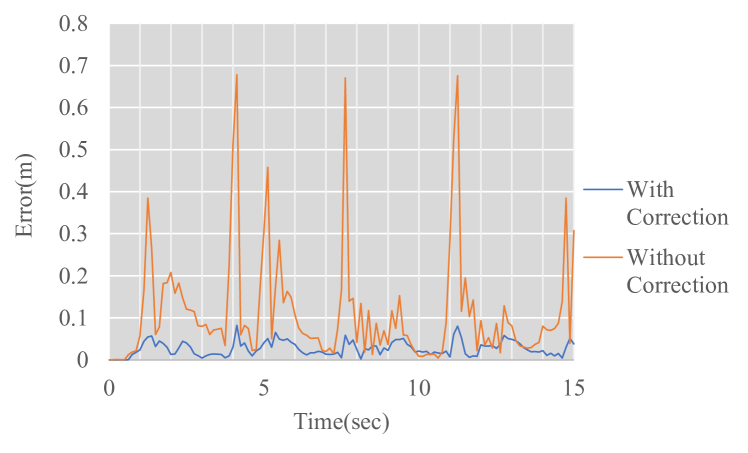
Next, we demonstrate the effectiveness of the online position correction method. We record both localized positions with and without correction in two dimensions during moving robot joints vigorously to validate our online correction method. While the robot is moving, the true value of the plotted foot position does not change in two dimensions since the joint moves but the position of the robot’s foot has not changed. However, when the joint of the robot is violently moved, an encoder error due to a time lag occurs, which causes an error in observed localized positions via HoloLens.
Figure 8 shows the result of plotting the error of the localized position of pepper’s foot from the initial position during the operation of the joint of the robot. In the offline calibration, we use the two-way rotation calibration method and rotate in the horizontal direction and the vertical direction twice respectively. During operation, an error of at least at maximum is recorded without correction, whereas the plot at the corrected position is less than . This result shows that the proposed position correction method can absorb the localization error.
VI-D Navigation
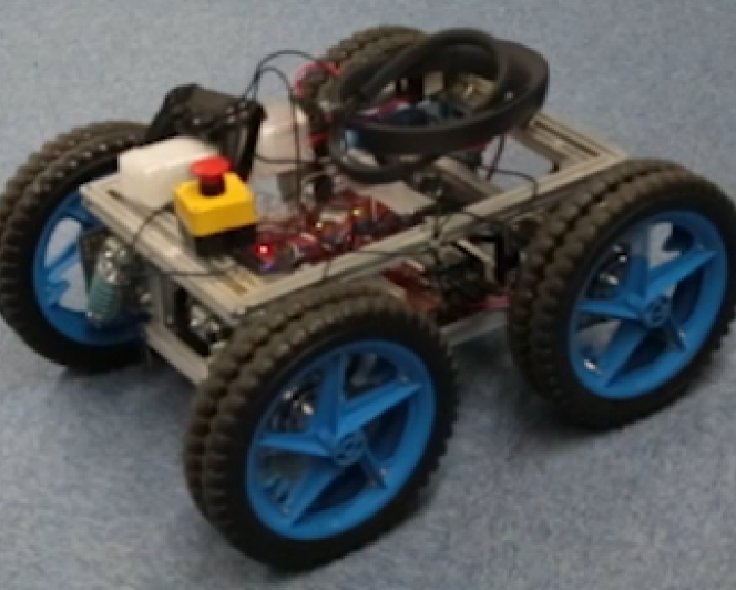
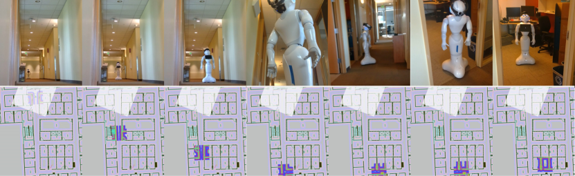
The steps for demonstrating the navigation system using Pepper and HoloLens are as follows: First, attach HoloLens to the head of Pepper, then establish communication with the host system and Pepper and HoloLens, and run navigation and localization program. After that, calibrate the Pepper’s head and HoloLens using two-way rotation transitions (Fig. 1 (a) and (b)). Regarding the localization of HoloLens, by specifying the position of HoloLens on a two-dimensional floor map manually through a GUI, alignment is performed using it as an initial position and a spacial anchor is installed. Finally, navigation is executed by specifying the destination on the 2D map. As shown in Fig. 10, it is also possible to navigate the rover by placing the SLAM device on it and applying calibration using horizontal movement
In the navigation, we make a global route plan using the Dijkstra method implemented in ROS’s NavFn 444http://wiki.ros.org/navfn package, create a cost map [19]. We used Dynamic Window Approach [20] for local route planning. Figure. 9 shows a continuous photograph of navigation where Pepper goes through a long corridor and enters the room.
VII Conclusion
In this paper, we proposed a calibration method between external SLAM device and a robot for navigation. Although a humanoid type robot attached with a SLAM device is used for the demonstration, the proposed method can be easily applied to various robots having a self-position estimation function. In the experiments, 2D floor maps created in advance are used, however, this system can be extended to mapless navigation and three-dimensional navigation.
ACKNOWLEDGMENT
Some part of the experiments was conducted with the assistance of the Strategic prototyping group, Microsoft. In particular, Yutaka Suzue’s help was greatly appreciated. We also appreciate Yoshihiro Sato, Computer Vision Laboratory, The University of Tokyo. This work was partly supported by the social corporate program (Base Technologies for Future Robots) sponsored by NIDEC corporation and supported by JSPS Research Fellow Grant No.16J09277.
References
- [1] F. Lu and E. Milios, “Robot pose estimation in unknown environments by matching 2d range scans,” Journal of Intelligent and Robotic systems, vol. 18, no. 3, pp. 249–275, 1997.
- [2] D. Fox, W. Burgard, F. Dellaert, and S. Thrun, “Monte carlo localization: Efficient position estimation for mobile robots,” AAAI/IAAI, vol. 1999, no. 343-349, pp. 2–2, 1999.
- [3] J. Ido, Y. Shimizu, Y. Matsumoto, and T. Ogasawara, “Indoor navigation for a humanoid robot using a view sequence,” The International Journal of Robotics Research, vol. 28, no. 2, pp. 315–325, 2009.
- [4] W. Winterhalter, F. Fleckenstein, B. Steder, L. Spinello, and W. Burgard, “Accurate indoor localization for RGB-D smartphones and tablets given 2D floor plans,” in Intelligent Robots and Systems (IROS), 2015 IEEE/RSJ International Conference on. IEEE, 2015, pp. 3138–3143.
- [5] S. Park and S. Hashimoto, “Autonomous mobile robot navigation using passive RFID in indoor environment,” IEEE Transactions on Industrial Electronics, vol. 56, no. 7, pp. 2366–2373, 2009.
- [6] L. George and A. Mazel, “Humanoid robot indoor navigation based on 2d bar codes: Application to the nao robot,” in Humanoid Robots (Humanoids), 2013 13th IEEE-RAS International Conference on. IEEE, 2013, pp. 329–335.
- [7] J. Engel, T. Schöps, and D. Cremers, “LSD-SLAM: Large-scale direct monocular SLAM,” in European Conference on Computer Vision. Springer, 2014, pp. 834–849.
- [8] R. Mur-Artal, J. M. M. Montiel, and J. D. Tardos, “ORB-SLAM: a versatile and accurate monocular SLAM system,” IEEE Transactions on Robotics, vol. 31, no. 5, pp. 1147–1163, 2015.
- [9] F. Endres, J. Hess, J. Sturm, D. Cremers, and W. Burgard, “3-D mapping with an RGB-D camera,” IEEE Transactions on Robotics, vol. 30, no. 1, pp. 177–187, 2014.
- [10] Y. Misono, Y. Goto, Y. Tarutoko, K. Kobayashi, and K. Watanabe, “Development of laser rangefinder-based SLAM algorithm for mobile robot navigation,” in SICE, 2007 Annual Conference. IEEE, 2007, pp. 392–396.
- [11] G. Klančar, L. Teslić, and I. Škrjanc, “Mobile-robot pose estimation and environment mapping using an extended Kalman filter,” International Journal of Systems Science, vol. 45, no. 12, pp. 2603–2618, 2014.
- [12] A. Oliver, S. Kang, B. C. Wünsche, and B. MacDonald, “Using the Kinect as a navigation sensor for mobile robotics,” in Proceedings of the 27th conference on image and vision computing New Zealand. ACM, 2012, pp. 509–514.
- [13] S. Wang, Y. Li, Y. Sun, X. Li, N. Sun, X. Zhang, and N. Yu, “A localization and navigation method with ORB-SLAM for indoor service mobile robots,” in Real-time Computing and Robotics (RCAR), IEEE International Conference on. IEEE, 2016, pp. 443–447.
- [14] Y. C. Shiu and S. Ahmad, “Calibration of wrist-mounted robotic sensors by solving homogeneous transform equations of the form AX= XB,” ieee Transactions on Robotics and Automation, vol. 5, no. 1, pp. 16–29, 1989.
- [15] F. C. Park and B. J. Martin, “Robot sensor calibration: solving AX= XB on the Euclidean group,” IEEE Transactions on Robotics and Automation, vol. 10, no. 5, pp. 717–721, 1994.
- [16] I. Fassi and G. Legnani, “Hand to sensor calibration: A geometrical interpretation of the matrix equation AX= XB,” Journal of Field Robotics, vol. 22, no. 9, pp. 497–506, 2005.
- [17] J. Kelly and G. S. Sukhatme, “Fast relative pose calibration for visual and inertial sensors,” in Experimental Robotics. Springer, 2009, pp. 515–524.
- [18] J. D. Hol, T. B. Schön, and F. Gustafsson, “Modeling and calibration of inertial and vision sensors,” The international journal of robotics research, vol. 29, no. 2-3, pp. 231–244, 2010.
- [19] D. V. Lu, D. Hershberger, and W. D. Smart, “Layered costmaps for context-sensitive navigation,” in Intelligent Robots and Systems (IROS 2014), 2014 IEEE/RSJ International Conference on. IEEE, 2014, pp. 709–715.
- [20] D. Fox, W. Burgard, and S. Thrun, “The dynamic window approach to collision avoidance,” IEEE Robotics & Automation Magazine, vol. 4, no. 1, pp. 23–33, 1997.