Measurements of Radiation Pressure owing to the Grating Momentum
2Charter School of Wilmington, Wilmington, Delaware
)
Abstract
The force from radiation pressure owing to the grating momentum was measured for a thin transmissive fused silica grating near the Littrow angles at wavelengths of 808 nm and 447 nm. A significant magnitude of force was measured in the direction parallel to the grating surface. We also confirmed that the component of force normal to the grating surface may vanish. This forcing law is characteristically different from radiation pressure on a reflective surface, and thus, opens new opportunities for light-driven applications such as solar or laser driven sailcraft, or the transport of objects in liquids.
Since Maxwell first predicted radiation pressure in 1873 [1], it has helped to describe phenomena ranging from the astronomical to the quantum realm. For example the gravitational collapse of stars and accretion dynamics are governed by radiation pressure [2, 3]. Experimental evidence of Kepler’s 1619 explanation of comet tails [4, 5] was later extended to the general distribution of interplanetary dust [6, 7]. Terrestial applications have found uses in biology as optical tweezers [8], laser cooling of atoms[9, 10] and macroscopic objects [11, 12]. The detection of gravitational waves by means of laser interferometers requires an accounting of radiation pressure [13]. Micro-structures such as optical wings [14] and slot waveguides have promising photonic applications [15, 16]. Thin microfabricated sheets such a diffraction gratings and diffractive metamaterials [17, 18, 19, 20, 21, 22, 23] provide opportunities to marry recent developments in materials research with grand ambitions for astronautical space travel. For example, radiation pressure is one of the few methods of reaching distant stars with free sunlight [24, 25] or expensive laser systems [26, 27]. While those sailcraft considered elementary attitude-controlled reflective sails, optical scientists have recently proposed passive or active diffractive sails that may provide superior control authority for near-Earth missions and beyond [28, 29], owing to force components along both the surface normal and tangent. Unlike a reflective sail that has only a normal component of force, a diffractive sail has both a tangential and a normal component of force. The latter is notable for changing sign, continuously passing through the zero-value point as the angle of incidence is varied. The large tangential component of force of a diffractive sail may be particularly advantageous for raising or lowering the orbit of a sailcraft[28]. The experimental measurements described below validate the premise that diffraction gratings experience wavelength-dependent force components in both the normal and transverse directions.
Although the magnitude of radiation pressure may seem relatively weak owing to its inverse relation to the speed of light, this value may be comparable to the gravitational force in outer space or in a quasi-neutrally buoyant liquid. This provides astronautical opportunities to propel low-mass sailcraft through space and a new laboratory technique to assert non-contact forces on small bodies. Light-driven sails being developed for future space travel afford cheap and inexhaustible energy for a myriad of missions [30, 31, 32]. Similar to the development of air flight in the early 1900’s, sailcraft technology is likely to rapidly advance after in-space demonstrations reveal the extent of navigation-by-light challenges. New materials and sailcraft architectures will be perfected to optimize particular mission objectives. For example, one may question the necessity of a reflective film that transfers electromagnetic momentum to mechanical momentum. A diffractive film provides advantages over a reflective film. For example, a micrometer-scale reflective film must be tilted to change the direction of force – a daunting task if the sail area is hundreds of square meters. However, non-mechanical beam steering of a diffractive element (e.g., using electro-optic techniques) overcomes this complication [33]. Although the concept of a grating momentum vector is commonly invoked to predict the direction of transmitted and reflected beams from a grating, to our knowledge, the radiation pressure force on diffraction grating plate has not been measured. Here we report our experimental investigation of the relationship between the grating momentum and radiation pressure force on a commercial grating. To our knowledge this is the first time such values have been measured.
The radiation pressure force on a grating may be expressed
| (1) |
where is the efficiency of the diffracted beam, () is the incident (diffracted) beam power, is the speed of light, () is the incident (diffracted) wave vector, with , and is the wavelength of the beam of light. Doppler shifts caused by the relative velocity of the grating are ignored here.

In this report we assume negligible absorption, convective, photophoretic, and outgassing forces. Further, the forcing laser beam is assumed to under-fill the grating surface. A depiction of incident and diffracted beams for a single diffraction order grating, with corresponding angles, , , and , is shown in Fig. 1. Phase-matching of the electromagnetic fields at the grating boundary provides a relation between the components of the wave vectors that are parallel to the surface:
| (2) |
where is the so-called grating momentum (the factor is typically ignored), is the grating period, is the diffraction order (for either the reflected or transmitted beam), and () is the unit vector parallel (normal) to the grating surface. The well-known grating equation is a restatement of Eq. (2): .
For an ideal grating with unity transfer efficiency into a single diffraction order the parallel and normal force components may be expressed
| (3a) | ||||
| (3b) | ||||
where the minus (plus) sign is for a transmissive (reflective) diffraction order. The force efficiency components, and of a transmissive grating are plotted in Fig. 2 for the allowed diffraction angle(s) at two wavelengths corresponding to our experiments: 808 nm and 447 nm. The parallel component of force is negative, as expected from conservation of momentum arguments (see Fig. 1). What is more, is independent of the incident angle when is satisfied. In contrast, the normal component of force is positive below the Littrow diffraction angle, defined by . For the normal component of force is negative and the light source acts as a partial ”tractor beam” [34, 35, 36, 37], pulling rather than pushing the grating. The normal force components vanish at the Littrow diffraction angle (marked as diamonds in Fig. 2). Light sailing and terrestrial applications inspired us to measure the components of force on a diffraction grating with a torsion oscillator [38].

The force on a non-ideal non-absorbing grating must account for multiple diffraction orders. In this case the parallel and normal components of force may be respectively expressed
| (4a) | ||||
| (4b) | ||||
In principle, Eq. (4b) may also allow a zero-valued normal force component, resulting in a purely tangential force, as described above.
We built a torsion oscillator using a 25 m diameter, =240 mm long tungsten filament (Alfa Aesar 10405-H4). It was attached to an aluminum support frame at one end, and a suspended twist-hardened copper wire of length 220 mm, diameter 1 mm, at the other end. An optimized single order diffraction grating (LightSmyth T-1850-800s-3210-93) having a period = 540 nm was ground to a thickness of 190 m and attached in one of two configurations: (A) with its surface normal parallel to the copper wire; (B) with its surface normal perpendicular to the copper wire (see Fig. 3). A balancing mass was placed on the other end of the wire. A small lightweight mirror was attached at the vertex of the wire and filament to allow measurements of the angular displacement, , of a low power HeNe tracking laser, where is the linear displacement of the laser beam from its equilibrium position on a screen placed a distance m from the pivot. Time lapse photographs (Canon 5D III and Canon TC-80N3) of the screen were recorded at s intervals. The position of the beam was obtained by determining the beam centroid in each image. The apparatus was transported to a suburban basement that was remarkably free of characteristic vibrations and loading sag experienced on our institutional building bedrock floor. An aluminum wire mesh was shaped into a mm high cylinder to serve as a Faraday cage, shielding the oscillator from inadvertent electrostatic torques. The system was centered within a customized borosilicate bell jar of good optical quality. After evacuating air from within the bell jar to a pressure of hPa ( Torr), the disturbed oscillator was brought to near rest by means of radiation pressure from the forcing laser. At this pressure the mean free path of the remaining air molecules exceeded the diameter of the bell jar. The system remained at rest for many hours – even while the vacuum system labored and people walked nearby. We attributed this stability to concrete-on-earth flooring.
The measured period of free oscillation was = 100.8 s, and the characteristic decay time () was roughly . Based on the calculated moment of inertia, kgm2, and the measured period, the torsional spring constant of the filament was determined to be Nm/rad. This value agreed well with the theoretical value obtained from a tabulated value of the Young’s modulus kNmm-2 [39]: Nm/rad. The discrepancy between the two values is attributed to the unknown value of for thin filaments of unknown working history, and to the unknown variability of along the length of the filament. We note that the radiation pressure force was not expected to induce significant linear pendular displacements of the hanging g mass. Several types of measurements are reported below.

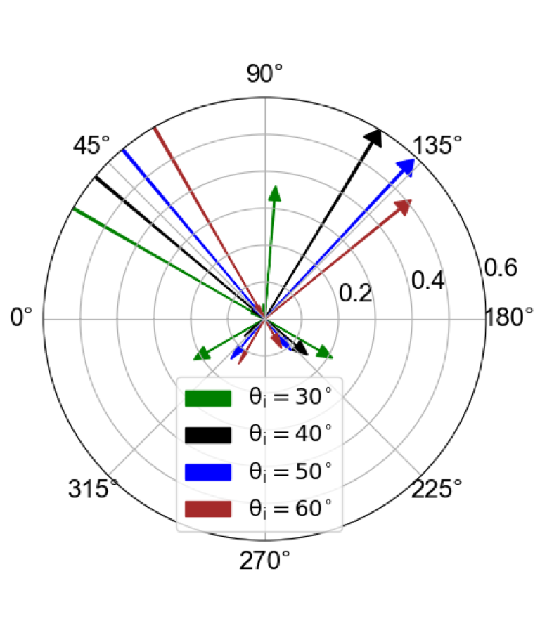
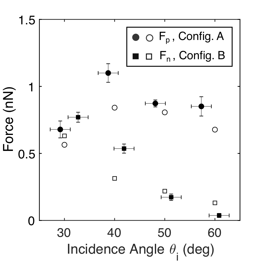
First we mounted the diffraction grating with its surface normal parallel to the copper torsion arm, as depicted in Fig. 3, configuration A. The grating lines were transverse to the plane of incidence. With the bell jar removed, the oscillator was immobilized to allow measurements of the transmitted, diffracted, and reflected beams with the forcing laser ( 808 nm, and linear polarization transverse to the plane of incidence). The measured diffraction efficiencies are depicted in Fig. 4(a) for four different angles of incidence: , , , . The transmitted first order diffraction efficiency was expected to be optimal near the Littrow angle . In fact both the and beam angles provided peak diffraction efficiencies of roughly . We believe of the beam power was lost owing to scattering attributed to micro scratches from the mechanical thinning process (see Table 1). Although the force from directional scattering may be small but non-zero, we were unable to measure the angular scattering spectrum; hence it is ignored in our analysis. To account for Fresnel reflections at the outer and inner diameters of the borosilicate bell jar we reduce the measured incident power with the angle-dependent, wavelength-dependent transmission factors listed in Table 1. The effective power incident on the diffraction grating may be expressed , where is the scattered power. The theoretically expected values of force (Eq. (4)) based on the effective incidence power are plotted in Fig. 4(b) (hollow circular data points) for a laser output power of mW. For example, we calculate N, with angular variations attributed to the diffraction efficiency of the grating and Fresnel coefficients of the bell jar.
| = 808 nm, | 30∘ | 40∘ | 50∘ | 60∘ | ||
|---|---|---|---|---|---|---|
| Config. A, | 0.89 | 0.87 | 0.83 | 0.78 | ||
| Config. B, | 0.78 | 0.83 | 0.87 | 0.89 | ||
| / | 0.17 | 0.19 | 0.13 | 0.23 | ||
| = 447 nm, | 15∘ | 25∘ | 35∘ | 45∘ | 55∘ | 65∘ |
| Config. A, | 0.9 | 0.9 | 0.88 | 0.85 | 0.8 | 0.74 |
| / | 0.21 | 0.33 | 0.36 | 0.23 | 0.29 | 0.27 |
Next we enclosed the oscillator within the bell jar, evacuated the chamber, and brought the free oscillator to near standstill. The forcing laser power was set to mW and a mechanical shutter was opened at time to provide a step function force on the grating. This procedure was repeated three times for each of the four incidence angles described above. The time-varying angular displacement of the tracking laser upon the screen was extracted and fitted to a well-known equation for a weakly damped harmonic oscillator (see Appendix). Fitting was achieved by varying and the strength of the step function force. Small amplitude pre-exposure oscillations were similarly fitted to obtain the state of the oscillator at . The excellent agreement between the experimental data and the theoretical model with the fitted force value (typical RMS error ) confirms the veracity of the model.
The magnitude of the tangential force determined by use of configuration A are plotted in Fig. 4(b) (solid circles with error bars). We find good agreement between the determined and predicted values of force. The force efficiency values, are represented by solid circular data points in Fig. 2. For an ideal single order grating, these values are expected to be constant. Although our grating was not ideal, the measured efficiency values were nearly constant over a range of angles (see solid gray line in Fig. 2), differing in magnitude by a factor of . This difference between the ideal and measured values is attributed to the additional reflected and transmitted diffraction orders in our experiment (see Fig. 4(a)).
To obtain experimental values of the normal component of force we changed the orientation of the diffraction grating to Configuration B (see Fig. 3). As described above, the values of force were determined from measured values of angular displacement. As shown in Fig. 4(b) these values are comparable to those predicted from Eq. (4). The normal component of force vanishes at , which is greater than the Littrow angle. Again this difference is attributed to the use of a non-ideal grating. The force efficiency values, are represented by open circular data points in Fig. 2, showing larger values than expected owing to the reflected diffraction order (see Fig. 4(a)). Unlike the constant value of efficiency for the component of force, the efficiency for the normal component decreases with increasing angle. One may expect the value to become negative for our experiment for angles greater than .
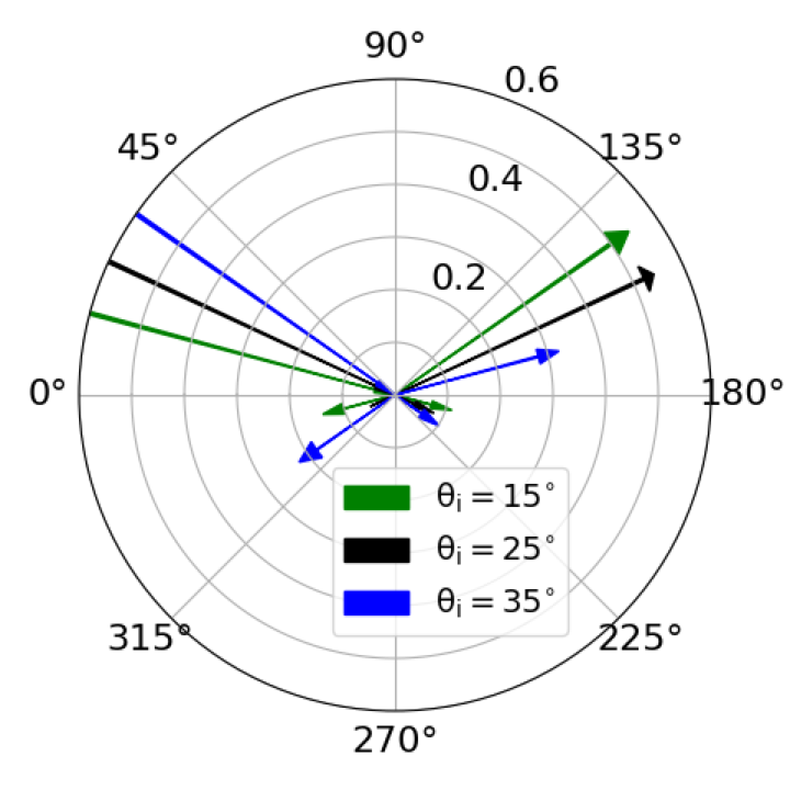
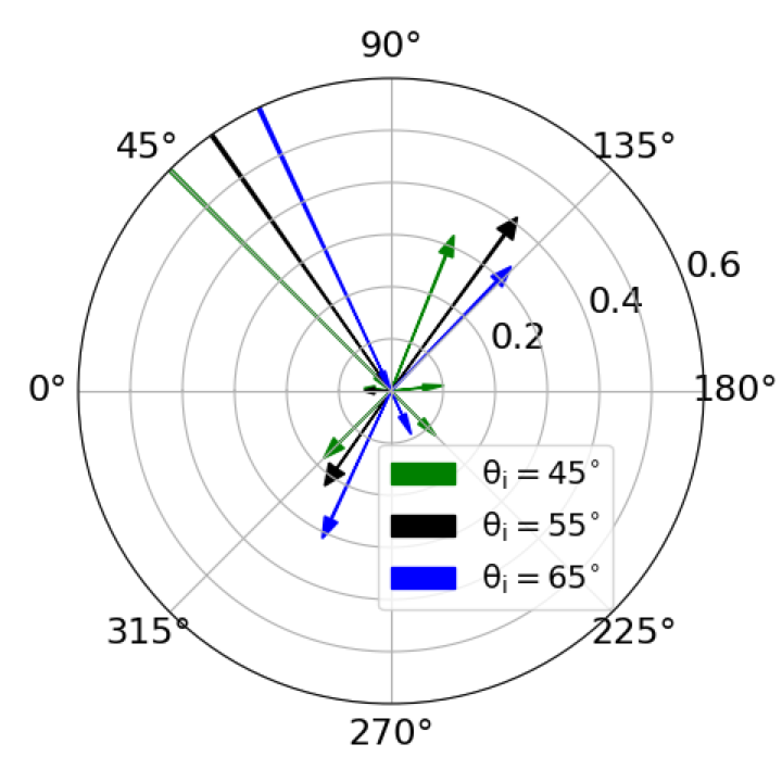
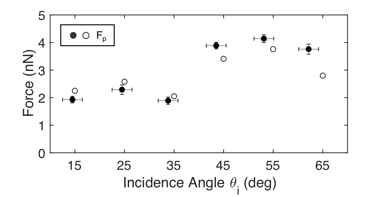
As the wavelength of light changes, the grating efficiency and number of orders may change. To assess how radiation pressure changes when the grating allows two diffraction orders, we substituted a laser having a wavelength nm. The procedures described above for Configuration A were repeated. Measurements were not made in Configuration B. At this wavelength two Littrow angles are allowed: for and for . The measured diffraction efficiency of each transmitted and reflected diffracted order is depicted in Fig.5(a,b), and the values of are plotted in Fig. 5(c) for a laser output power W. As expected the magnitudes of force are relatively constant, with the second order values roughly twice the first order values, as expected (see Fig. 2). The average measured force efficiencies, 0.67 for and 1.34 for differ by factor of 2.0, as expected. Although the grating was not designed for use at nm, the measured values of efficiency agree remarkably well () with the ideal case.
In summary, we have used a vacuum torsion oscillator in two configurations and at two different wavelengths to measure the radiation pressure force on a diffraction grating. We have verified that unlike an ideal flat reflective surface, which is known to have only a normal component of force, a diffraction grating generally experiences radiation pressure force components that are perpendicular to and parallel to the surface. The tangential component is a direct mechanical manifestation of the grating momentum vector. As expected, we found that the latter force is roughly constant and proportional to the grating momentum, whereas the normal component varied with the angle of incidence. The normal component of force vanished, producing a purely tangential force when . The measured forces were in good agreement with predicted values based on measured diffraction angles and efficiencies, with differences attributed to multiple diffraction orders and scattering. To our knowledge, this is the first quantitative confirmation of the equivalence of the grating momentum and mechanical momentum of a diffraction grating. Further, these results highlight the opportunity to replace reflective sailcraft with diffractive sails. To further advance the performance of diffractive sailcraft, large area single order gratings having a high diffraction efficiency at either a single wavelength (in the case of a laser-driven sail) or across a broad region of the solar spectrum (in the case of a sun-driven sail) may be developed.
References
- [1] James Clerk Maxwell. A treatise on electricity and magnetism, volume 1. Clarendon press, 1881.
- [2] Karl Schwarzschild. Der Druck des Lichts auf kleine Kugeln und die Arrhenius’sche Theorie der Cometenschweife. Verlagd. K. Akad., 1901.
- [3] AS Eddington. Stars, gaseous, on the pulsations of a gaseous star. Monthly Notices of the Royal Astronomical Society, 79:2–22, 1918.
- [4] PN Lebedev. Investigations on the pressure forces of light. Ann. Phys, 6:433–458, 1901.
- [5] EF Nichols and GF Hull. The application of radiation pressure to cometary theory. The Astrophysical Journal, 17:352, 1903.
- [6] LM Gindilis, NB Divari, and LV Reznova. Solar radiation pressure on particles of interplanetary dust. Soviet Astronomy, 13:114, 1969.
- [7] G Schwehm. Radiation pressure on interplanetary dust particles. In Interplanetary Dust and Zodiacal Light, pages 459–463. Springer, 1976.
- [8] Arthur Ashkin. Applications of laser radiation pressure. Science, 210(4474):1081–1088, 1980.
- [9] Paul D Lett, Richard N Watts, Christoph I Westbrook, William D Phillips, Phillip L Gould, and Harold J Metcalf. Observation of atoms laser cooled below the doppler limit. Physical review letters, 61(2):169, 1988.
- [10] Jean Dalibard and Claude Cohen-Tannoudji. Laser cooling below the doppler limit by polarization gradients: simple theoretical models. JOSA B, 6(11):2023–2045, 1989.
- [11] Constanze Höhberger Metzger and Khaled Karrai. Cavity cooling of a microlever. Nature, 432(7020):1002, 2004.
- [12] M Bhattacharya, AN Vamivakas, and P Barker. Levitated optomechanics: introduction. Journal of the Optical Society of America B, 34(6):LO1–LO2, 2017.
- [13] Thomas Corbitt, David Ottaway, Edith Innerhofer, Jason Pelc, and Nergis Mavalvala. Measurement of radiation-pressure-induced optomechanical dynamics in a suspended fabry-perot cavity. Physical Review A, 74(2):021802, 2006.
- [14] Grover A Swartzlander Jr, Timothy J Peterson, Alexandra B Artusio-Glimpse, and Alan D Raisanen. Stable optical lift. Nature Photonics, 5(1):48, 2011.
- [15] Allen HJ Yang, Sean D Moore, Bradley S Schmidt, Matthew Klug, Michal Lipson, and David Erickson. Optical manipulation of nanoparticles and biomolecules in sub-wavelength slot waveguides. Nature, 457(7225):71–75, 2009.
- [16] Qing Liu, Xiaoguang Tu, Kyung Woo Kim, Jack Sheng Kee, Yong Shin, Kyungsup Han, Yong-Jin Yoon, Guo-Qiang Lo, and Mi Kyoung Park. Highly sensitive mach–zehnder interferometer biosensor based on silicon nitride slot waveguide. Sensors and Actuators B: Chemical, 188:681–688, 2013.
- [17] Wilhelm Stork, Norbert Streibl, H Haidner, and P Kipfer. Artificial distributed-index media fabricated by zero-order gratings. Optics letters, 16(24):1921–1923, 1991.
- [18] Chulwoo Oh and Michael J Escuti. Achromatic diffraction from polarization gratings with high efficiency. Optics letters, 33(20):2287–2289, 2008.
- [19] Oleg D Lavrentovich. Liquid crystals, photonic crystals, metamaterials, and transformation optics. Proceedings of the National Academy of Sciences, 108(13):5143–5144, 2011.
- [20] Lorenzo Marrucci. The q-plate and its future. Journal of Nanophotonics, 7(1):078598, 2013.
- [21] Yong Zhang, Lin Zhou, Jia-qi Li, Qian-jin Wang, and Cheng-ping Huang. Ultra-broadband and strongly enhanced diffraction with metasurfaces. Scientific reports, 5:10119, 2015.
- [22] Nelson V Tabiryan, Svetlana V Serak, David E Roberts, Diane M Steeves, and Brian R Kimball. Thin waveplate lenses of switchable focal length-new generation in optics. Optics Express, 23(20):25783–25794, 2015.
- [23] Shulabh Gupta. Single-order transmission diffraction gratings based on dispersion engineered all-dielectric metasurfaces. JOSA A, 33(8):1641–1647, 2016.
- [24] Robert H Frisbee. Limits of interstellar flight technology. Frontiers of Propulsion Science, 227:31–126, 2009.
- [25] Paul Gilster. Centauri dreams: imagining and planning interstellar exploration. Springer Science & Business Media, 2004.
- [26] George Marx. Interstellar vehicle propelled by terrestrial laser beam. Nature, 211(5044):22, 1966.
- [27] Robert L Forward. Roundtrip interstellar travel using laser-pushed lightsails. Journal of Spacecraft and Rockets, 21(2):187–195, 1984.
- [28] Grover A Swartzlander Jr. Radiation pressure on a diffractive sailcraft. JOSA B, 34(6):C25–C30, 2017.
- [29] Karim Achouri and Christophe Caloz. Metasurface solar sail for flexible radiation pressure control. arXiv preprint arXiv:1710.02837, 2017.
- [30] Colin R McInnes. Solar sailing: technology, dynamics and mission applications. Springer Science & Business Media, 2013.
- [31] Charles Garner, Benjamin Diedrich, and Manfred Leipold. A summary of solar sail technology developments and proposed demonstration missions. NASA technology report, (JPC-99-2697), 1999.
- [32] Les Johnson, Mark Whorton, Andy Heaton, Robin Pinson, Greg Laue, and Charles Adams. Nanosail-d: A solar sail demonstration mission. Acta Astronautica, 68(5):571–575, 2011.
- [33] Yuichi Tsuda, Osamu Mori, Ryu Funase, Hirotaka Sawada, Takayuki Yamamoto, Takanao Saiki, Tatsuya Endo, Katsuhide Yonekura, Hirokazu Hoshino, and Jun’ichiro Kawaguchi. Achievement of ikaros-japanese deep space solar sail demonstration mission. Acta Astronautica, 82(2):183–188, 2013.
- [34] Andrey Novitsky, Cheng-Wei Qiu, and Haifeng Wang. Single gradientless light beam drags particles as tractor beams. Physical review letters, 107(20):203601, 2011.
- [35] S Sukhov and A Dogariu. Negative nonconservative forces: optical ”tractor beams” for arbitrary objects. Physical review letters, 107(20):203602, 2011.
- [36] S Sukhov and A Dogariu. On the concept of ”tractor beams”. Optics letters, 35(22):3847–3849, 2010.
- [37] Darwin Palima, Andrew Rafael Bañas, Gaszton Vizsnyiczai, Lóránd Kelemen, Thomas Aabo, Pál Ormos, and Jesper Glückstad. Optical forces through guided light deflections. Optics express, 21(1):581–593, 2013.
- [38] GT Gillies and RC Ritter. Torsion balances, torsion pendulums, and related devices. Review of scientific instruments, 64(2):283–309, 1993.
- [39] Modulus of elasticity or young’s modulus - and tensile modulus for common materials. ”http://www.engineeringtoolbox.com/young-modulus-d_417.html”. Accessed on 2017-12-21.
Appendix
The equation of motion for angular displacement may be expressed
| (5) |
where is a damping constant, is a step function, and is the shutter release time. For small angular displacements, we assume the driving force, is a constant. The solution of Eq. (5) is found via Laplace transform techniques: where
| (6) |
| (7) |
where is the unforced solution of Eq. (5) for , , , is the oscillation frequency, is the natural oscillation frequency, and is the initial phase at .
Acknowledgement
We thank Peter and Lihong Jansson (Hockessin, DE) for guidance and the hospitable use of their laboratory, and Sydor Optics (Rochester, NY) for thinning and dicing the diffraction grating. This research was partially supported by the National Science Foundation under Directorate for Engineering(ENG) (ECCS-1309517).