Microwave cavity tuned with liquid metal and its application to Electron Paramagnetic Resonance
Abstract
This note presents a method to tune the resonant frequency of a rectangular microwave cavity. This is achieved using a liquid metal, GaInSn, to decrease the volume of the cavity. It is possible to shift by filling the cavity with this alloy, in order to reduce the relative distance between the internal walls. The resulting modes have resonant frequencies in the range GHz. The capability of the system of producing an Electron Paramagnetic Resonance (EPR) measurement has been tested by placing a 1 mm diameter Yttrium Iron Garnet (YIG) sphere inside the cavity, and producing a strong coupling between the cavity resonance and Kittel mode. This work shows the possibility to tune a resonant system in the GHz range, which can be useful for several applications.
type:
NoteC.S.Gallo1, E.Berto2, C.Braggio2,3, F.Calaon3, G.Carugno2,3, N.Crescini1,3, A.Ortolan1, G.Ruoso1, M.Tessaro3
Keywords: microwave cavity, tunable resonance, liquid metal, Electron Paramagnetic Resonance, GaInSn Resonant cavities are typically completely enclosed by conducting walls that can contain oscillating electromagnetic fields. The resonant frequency of a mode in a rectangular cavity depends on the distances between the internal surfaces of the walls. Imposing the boundary conditions on the electromagnetic field trapped inside the cavity, it is possible to obtain an analytic expression of the resonant frequency for the mode. If we call the dimensions of a cavity filled with vacuum, this calculation yields
| (1) |
where is the speed of light in vacuum [1]. Eq.(1) states that a cavity resonates at frequencies which are determined by the dimensions of the resonant cavity: as the cavity dimensions increase, the resonant frequencies decrease, and vice versa. Thus a reduction of one of this distances necessarily results in increased resonant frequencies of the modes, allowing a tuning of the cavity within certain ranges.
To shift the resonance frequency of a chosen mode we change one single dimension by filling the cavity with a liquid metal. It is to be noticed that this is not the only way to shift the resonance frequency of a mode, for example it is possible to insert dielectric materials into the cavity [2, 3, 4, 5, 6, 7, 8]. The copper cavity used in this work has dimensions ; we aim to shift the resonance frequency of a Transverse Magnetic mode (TM102), whose resonance frequency is 7.093 GHz. The cavity partially filled with liquid metal is shown in Fig.(1).
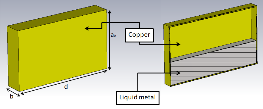
Let us call , and , the coordinate in the vertical direction and resonant frequencies of the empty and filled cavity, respectively. We tune the resonant frequency of the selected mode injecting different volumes of a liquid metal. We have selected GaInSn (liquid metal at room temperature), which is an eutectic mixture of the metals gallium, indium and tin. We control the volume of the injected metal using a syringe connected to the cavity by a copper tube as shown in Fig.(2). The dimensions of copper tube are not important, in our experiment we used a copper tube 130 mm long and with 1.78 mm of diameter.
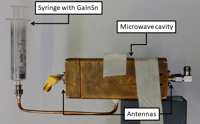
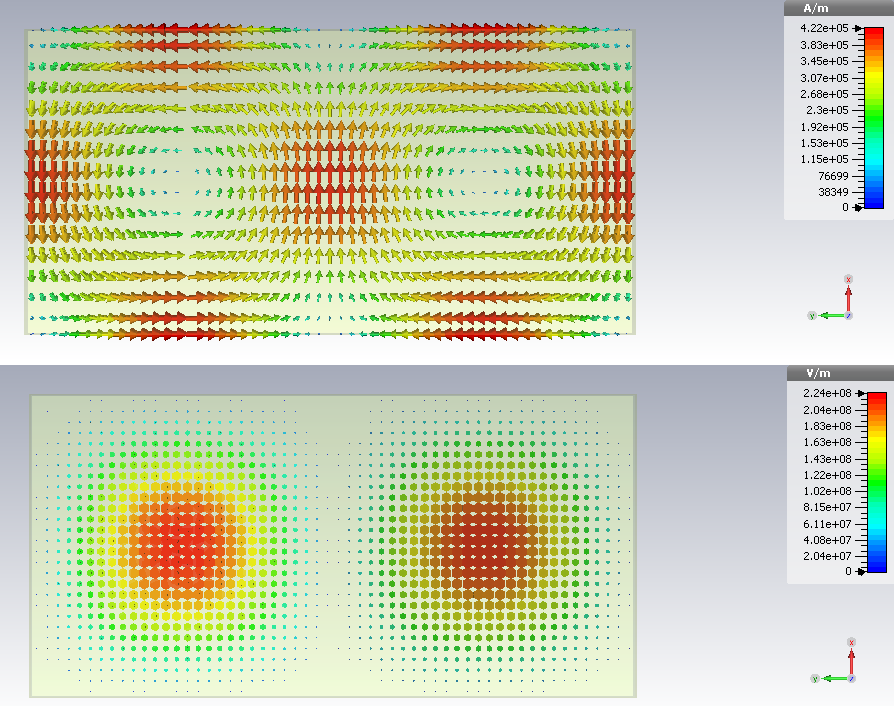
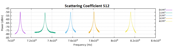
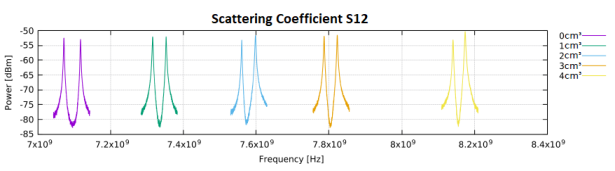
The measures were made at room temperature. The measures consist of steps. For every step the volume of liquid metal inside the cavity is increased of 1 cm3. In each step, we measured the scattering parameters of the system using a Network Analyzer, which is connected to the microwave cavity by two loop antennas (see Fig.(2)). For each variation of the cavity volume, we simulated the system by CST Microwave Studio to find the resonant frequencies, and the electromagnetic field of the TM102 cavity mode. In Fig.(3) we report an example of the fields in the cavity without liquid metal. While in Fig.(4) we show the measurements of the module of the transmission coefficient (S12) at different volume of liquid metal, taken with the Network Analyzer.
Now we were able to compare the frequencies measured with the simulated ones. The results are reported in Tab.(1).
-
•
[cm3] [mm3] [GHz] [GHz] 0 30.01060 7.066 7.093 2728 1 28.31060 7.282 7.333 2156 2 26.71060 7.516 7.580 2106 3 25.01060 7.805 7.806 2296 4 23.31060 8.146 8.159 2039
As expected, the resonant frequencies change in good agreement with the simulations and the loaded quality factors of the modes does not differ drastically from those of the empty cavity. We have thus shown that it is possible to tune the resonance frequencies of a cavity filled with a liquid metal.
Now we demonstrate that the system can be used for a physical application like an Electron Paramagnetic Resonance (EPR) experiment. In this way we tested the coupling of the cavity with a ferromagnetic resonance of a magnetic material placed inside. The cavity is equipped with a magnetized sample of volume and then placed inside an electromagnet that generates a static magnetic field . In a ferromagnetic material, electron spins tend to align parallel to the external magnetizing field and the Larmor frequency of the ferromagnetic resonance reads , where is the electron gyromagnetic ratio. If the total number of spin of the sample is sufficient, when the Larmor frequency and the cavity resonance coincide, the resonant mode of the system splits in two separate modes (hybridization). The mode separation is given by the total coupling strength , where is the spin density of the material, is the volume of the material, is the single spin coupling, is the volume of the cavity and [9]. To measure the hybridization, with the loop antennas, in addition to the field , an RF field is applied to the sample in a direction orthogonal to . We placed a 1 mm diameter Yttrium Iron Garnet (YIG) sphere in the center of the cavity, where the RF magnetic field is maximum (see Fig.(3)). This material has very high spin density m-3. The volume of the material is m-3, so the total expected coupling strength is .
We also performed 5 measures, labelled with , for the system cavity plus YIG. For every step the volume of liquid metal inside the cavity has been increased of 1 cm3. We measured the scattering parameters of the system using the Network Analyzer. The results of measurements are reported in Tab.(2), and in Fig.(5) we show the measurements of the module of the transmission coefficient (S12) of hybrid system at different volume of liquid metal.
-
•
[cm3] [T] [GHz] [GHz] 0 0.253 7.071 4159 7.117 4448 1 0.262 7.315 3325 7.353 3501 2 0.270 7.561 3979 7.599 2923 3 0.279 7.778 3709 7.824 3556 4 0.291 8.141 3540 8.174 3027
If we consider, for example, the cavity without liquid metal, the single spin coupling is Hz, so the total coupling strength is Hz. The total coupling strength measured is Hz, which are comparable within about 10%. The system works as expected, and for all the different levels of liquid metal we were able to obtain hybridization. This demonstrates the capability of our tunable resonant system of performing EPR measurement.
In conclusion, in this note we introduce a new method to tune the frequencies of the modes of cavities using liquid metal, and how it can be exploited in an EPR application. This process has been verified in the GHz frequency range, however we can sweep over different frequency ranges by changing the geometry of the empty cavity.
References
References
- [1] Pozar D 2004 Microwave Engineering (Wiley) ISBN 9780471448785
- [2] Liu X, Katehi L P B, Chappell W J and Peroulis D 2010 Journal of Microelectromechanical Systems 19 774-784 ISSN 1057-7157
- [3] Stefanini R, Chatras M, Pothier A, Orlianges J C and Blondy P 2009 High q tunable cavity using dielectric less rf-mems varactors 2009 European Microwave Integrated Circuits Conference (EuMIC) pp 391-394
- [4] Perigaud A, Pacaud D, Delhote N, Tantot O, Bila S, Verdeyme S and Estagerie L 2016 Frequency-tunable microwave-frequency wave filter with a dielectric resonator including at least one element that rotates uS Patent 9,343,791
- [5] E K 1969 Tunable microwave cavity using a piezoelectric device uS Patent 3,471,811
- [6] C Carvalho N, Fan Y and Tobar M 2016 Review of Scientic Instruments 87 094702
- [7] Sakaguchi J, Gilg H, Hayano R, Ishikawa T, Suzuki K, Widmann E, Yamaguchi H, Caspers F, Eades J, Hori M, Barna D, Horvth D, Juhsz B, Torii H and Yamazaki T 2004 Nuclear Instruments and Methods in Physics Research Section A: Accelerators, Spectrometers, Detectors and Associated Equipment 533 598 – 611 ISSN 0168-9002 URL http://www.sciencedirect.com/science/article/pii/S0168900204014639
- [8] Carter P S 1961 IRE Transactions on Microwave Theory and Techniques 9 252–260 ISSN 0097- 2002
- [9] Tabuchi Y, Ishino S, Ishikawa T, Yamazaki R, Usami K and Nakamura Y 2014 Phys. Rev. Lett. 113(8) 083603