Opposed flow focusing: evidence of a second order jetting transition
Abstract
We propose a novel microfluidic “opposed-flow” geometry in which the continuous fluid phase is fed into a junction in a direction opposite the dispersed phase. This pulls out the dispersed phase into a micron-sized jet, which decays into micron-sized droplets. As the driving pressure is tuned to a critical value, the jet radius vanishes as a power law down to sizes below 1 m. By contrast, the conventional “coflowing” junction leads to a first order jetting transition, in which the jet disappears at a finite radius of several m, to give way to a “dripping” state, resulting in much larger droplets. We demonstrate the effectiveness of our method by producing the first microfluidic silicone oil emulsions with a sub micron particle radius, and utilize these droplets to produce colloidal clusters.
pacs:
I Introduction
The controllable production of micron scale emulsions is an area of highly active research. Allowing extreme reductions in sample volumes, microdroplets currently find use across both fundamental research and industrial applications. One promising manufacturing method for these droplets is microfluidic emulsification theberge2010 . Offering unparalleled control over droplet formation, microfluidic emulsification systems find use across applications as diverse as the generation of artificial cells martino2016 , high-throughput screening of patient samples beebe2002 ; guo2012 ; yi2006 ; delamarche2005 , colloidal model systems meissner2017 , or even traffic dynamics champagne2010traffic .
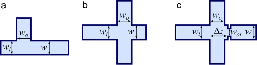
Conventionally, droplet generation in a microfluidic device is achieved via three main geometries as shown in Fig. 1: (a) T-junctions in which viscous shear stress at one fluid interface pulls off droplets into the flow of a second immiscible fluid thorsen2001 , (b) coflowing devices where an outer continuous phase fluid flows parallel to and surrounding an inner dispersed phase fluid until droplet generation occurs via stretching of the fluid interface ganan-calvo2001 , and flow-focusing devices, where the interface between coflowing streams are forced through a flow constriction causing droplet breakup through the generation of a velocity gradient anna2003 .
However, while these methods can effectively produce droplets with sizes below 100 m, the production of true micro-droplets with sizes below 10 m in diameter via microfluidic means remains a significant challenge. Typical droplet sizes realized in previous microfluidic setups are summarized in Table 1. To produce smaller droplets, one possibility is to reduce the size of the microfluidic device, but this is limited by the resolution of the manufacturing process available garstecki2005 . In addition, small channel sizes lead to large velocity gradients and large pressure gradients needed to drive the flow. In particular, oil-in-water emulsification remains a largely unexplored field.
| Droplet generation method | Emulsion type | Water droplet diameter | Oil droplet diameter |
|---|---|---|---|
| T-junction droplet generation | Water-in-oil nisisako2002 or oil-in-water nisisako2005 | 50 m | 100 m |
| Capillary coflow droplet generation | Water-in-oil or oil-in-water haase2014 | 20 m | 10 m |
| Flow focusing | Water-in-oil anna2003 or oil-in-water bauer2011 | 10 m | 20 m |
| Partial wetting | Fluorinated oil in water cohen2014 | - | 6 m |
| Geometric break-up | Water in oil link2004 | 50 m | - |
| Tip-streaming | Water in oil jeong2012 | 3 m | - |
Attempts to overcome this size limitation include methods of switching to more robust polymeric materials from which the device is comprised such as Norland adhesives to allow smaller geometries meissner2017 , using multiple coaxial jets ganan-calvo2007 , or utilizing electric fields to induce electro-hydrodynamic jetting G97 ; HLGVMP12 . While each of these methods begins to address the problem in their individual way, they all carry significant limitations in terms of technical complexity or system inflexibility. Here we pursue the alternative route of using suitably chosen flow characteristics to focus the inner phase into a very thin jet, whose radius is no longer limited by the device size.
Droplet production from a highly focused jet, also known as tip streaming, is a flow mode in which a thin jet emerges from a nearly conical point taylor1934 ; suryo2006 ; castrohernandez2012 ; anna2016 . The jet is subject to the Rayleigh-Plateau instability EV08 , and decays into droplets further downstream, whose sizes are set by the radius of the jet. However, the circumstances under which such a jet is produced are not understood, and depend crucially on the confined flow conditions realizable in a microfluidic device anna2016 . In unbounded flows produced by a four-roll mill, G.I. Taylortaylor1934 was able to deform the end of a drop into a conical tip, yet tip streaming occurred only when a small amount of surfactant was added. As the system was drained of surfactant, the jet disappeared once again.
A similar phenomenon was observed in the selective withdrawal geometry, in which an upper fluid phase is withdrawn through a nozzle from near the interface between two fluids layered atop of one another cohen2002 ; case2007 . As the flow rate is slowly increased, the interface is deformed into an increasingly sharp “hump”. When the tip of the hump has reached a radius of curvature of about 200 m, it transitions toward a “spout”, in which a thin jet is entrained into the nozzle; with increasing flow rate, the jet becomes thicker.
However, there is hysteresis in the system: one needs to go to lower flow rates for the spout to disappear than those at which the spout was first formed. Thus this system bears the characteristics of a first order transition: firstly, it is discontinuous, in that the jet radius jumps from zero (no jet) to a finite value, and vice versa. Secondly, there is hysteresis, in that the values of the control parameter are different depending on whether one passes from jet to no jet or vice versa. Both the hump and the spout states are characterized by a power-law dependence of their characteristic sizes as the control parameter approaches a critical value. This indicates that one is close to a second order transition, in which the characteristic size goes to zero, so that the transition from jet to no jet is continuous.
The aim of this paper is to use the precise control over the flow field made possible by microfluidics in order to realize this hypothetical second order transition. As the difference between the two states vanishes at a second order transition, we also expect there to be no hysteresis in that case. Achieving a second order transition would mean that the length scale of the jet is no longer set by the size of the microfluidic setup, but rather by our ability to tune the flow parameters close to the transition.
Recently, there has been some progress describing the formation of narrow tips and thin jets in microfluidic devices, both experimentally and computationally anna2016 . Usually this is achieved by extracting the dispersed fluid from a nozzle with an exterior phase flowing in the same direction (the coflowing configuration). In this situation the “jetting” state, which allows for the formation of the smallest drops, competes with a “dripping” state, characterized by the periodic formation of individual drops from near the nozzle opening utada2007 .
This is what is known as an “absolute instability” Cho05 ; UFGW08 , in that breakup occurs in the frame of reference of the nozzle. By contrast, drop formation from the jet occurs by a “convective instability”, which grows in a frame of reference convected with the flow. Numerical calculations in simple flow geometries have confirmed the possibility of creating thin jets from the tip of conical points suryo2006 ; castrohernandez2012 . However, jet radii have not been reported in a systematic fashion; in particular, the crucial question of what limits the size of the smallest jet has not been addressed.
In this paper, we contrast jetting in the conventional coflowing geometry with a novel opposed flow geometry. In agreement with previous results, we find in the former case that the smallest jet size is limited by transition to a dripping state. In the opposed flow geometry, on the other hand, dripping is suppressed, and the smallest jet size of about 1m appears to be limited only by our ability to adjust parameters close to a second order transition. This represents a significant improvement over droplet sizes of 10 m typically available from conventional flow focusing and opens the way to even smaller droplets than those we have produced here. The droplets produced this way are small enough so that they are susceptible to the thermal energy of the system, i.e. they are colloidal. Assemblies of such droplets have a well-defined thermodynamic state and thus can reach their ground state.
One experimental system where the size of these droplets can be readily exploited is the study of colloidal clusters. Displaying structural ordering rather different from that of bulk materials, colloidal clusters represent one of the clearest links between local geometry and bulk condensed matter malins2013tcc . In particular, due to the five-fold symmetry found in structures such as icosahedral and decahedral, colloidal clusters can act as model systems for both biological systems such as viral capsids, or materials such as glass where colloidal model systems have led to great insight into how atoms self-organize into energy minimizing locally favored structures malins2009 ; meng2010 ; malins2013tcc ; klix2013 . We demonstrate the utility of the droplets produced via our opposed flow-focusing methods by producing colloidal clusters of droplets via the addition of a depletion potential.
This paper is organized as follows: in Sect. II the experimental details and protocols will be described. In Section III we contrast the two flow geometries, and discuss their scaling properties in detail. As a potential application, we demonstrate the formation of colloidal clusters. We conclude by summarizing our findings and exploring their implications.
II Materials and Methods
II.1 Device assembly
Device patterns were fabricated on silicon wafers using standard photolithographic methods. Etched wafers were treated with trichloro(1H,1H,2H,2H-perfluorooctyl) silane to allow easy siloxane lift-off. Polydimethylsiloxane(PDMS) was mixed up in a 10:1 ratio of elastomer to curing agent (Sylgard 184). The mixed silicone elastomer was degassed, and approximately 20 g was poured on the silicon wafers, degassed a second time to remove any remaining bubbles, and heat cured at 60 ∘C for 6 hours. Once cured, PDMS layers were cut to shape and carefully removed from the silicon wafer. Tubing connectors were punched into the PDMS slabs using a mm diameter biopsy punch. The cut and punctured PDMS was subsequently thoroughly washed with isopropanol to clean out any PDMS remnants from the puncturing process. The PDMS chips were then plasma treated for 30 s in a 100 W Diener plasma cleaner. Immediately following plasma treatment, the device chip was brought into contact with a similarly prepared glass microscope slide, bonding the activated surfaces together.
We consider two different flow geometries, as shown in Fig. 2, produced from the same device with a central straight oil channel, to which four water side channels are attached in an x-shaped configuration. Two of the side channels are not punctured during the fabrication process, and therefore are blocked when liquid flows through the device. In the opposed flow system, shown in Fig. 2(a), the oil channel is connected so that oil flows from the side of the blockage, so that the water channel makes a 165∘ angle with the oil channel. Figure 2(b) shows the coflowing system, in which the oil comes from the direction of the open channels, leading to an angle of 15∘ between the aqueous and the oil flow.
II.2 PDMS surface coating
The hydrophobic surface properties of PDMS lead to clogging when producing oil-in-water emulsions. We overcome this difficulty by covering the PDMS with several layers of polymer coating bauer2010 , which were applied by flowing alternating polymer electrolyte solutions through the channel by use of a syringe pump. Layers were applied as follows: first 4 l of poly(allylamine hydrochloride) (PAH), a positively charged electrolyte, was inserted into the channel, so that it coated the negatively charged PDMS surfaces. This was followed by depositing the same volume of poly(sodium 4-styrenesulfonate) (PSS), a negatively charged electrolyte, onto the PAH layer. In total, four layers of PAH and PSS were applied to the PDMS surfaces. In between polymer electrolyte segments, 2 l of NaCl solution was flushed through the channels to remove excess charge. The solutions of PAH and PSS were used at the same concentration of 0.1 % w/v in 0.5 M NaCl, and the concentration of the NaCl solution used for washing in between the polymer segments was 0.1 M. These segments were loaded into a length of tubing, and flushed through the PDMS device at a flow rate of 50 l/h.
II.3 Droplet and jet production
Jetting experiments were carried out by connecting the assembled PDMS chip to a pressure pump (Fluigent MFCS) with polyethylene tubing. Silicone oil (shear viscosity 4.57 mPas) dyed with nile red was used as the dispersed phase and the continuous phase was a mixture of water and glycerol (30 : 70 wt) with viscosity 23 mPa s. This leads to a viscosity ratio of outer to inner phase 5.0. In order to produce a stable jet, we reduced the surface tension by adding 21mM of sodium dodecyl sulfate (SDS) to the aqueous phase, which is the maximum concentration that would go in solution. Since this is several times the critical micelle concentration (CMC) CDA08 , we believe that replacement of surfactant at the interface is so fast that the surface tension can be considered constant anna2016 .


The driving pressure was controlled using MaesFlo 3.2 software (Fluigent, Paris, France). Pressures were adjusted until the oil flow was stable and producing droplets, as shown in Fig. 2 for the opposed flow (left) and coflowing geometries (right). Once stable droplet formation was achieved, flow parameters were adjusted by either holding the external pressure constant and varying the internal pressure, or vice versa. The former mode of control is illustrated in Figs. 3 and 4 for the opposed flow geometry. As the internal pressure is lowered, the jet radius becomes very thin, and the oil drop near the nozzle exit assumes an almost conical shape, from which the jet emerges. In Fig. 4(a), each color represents the jet radius as the inner phase pressure is decreased, while the outer phase pressure was held fixed at a certain value from 1034 to 700 mbar. In Fig. 4(b) we show that all curves can be brought to a near collapse by plotting the radius as a function of the pressure ratio , establishing that this ratio is the main parameter determining the state of the system.
II.4 Cluster formation
Droplets obtained via the opposed flow focusing geometry were formed into clusters via the addition of non-adsorbing polymers. To this end droplets approximately 1.5 m in radius were produced, with the aqueous phase containing 6.34 mg/ml hydroxyethyl cellulose (HEC). With the radius of gyration of HEC being 50 nm, this leads to a colloid to polymer size ratio of approximately . Collection of the droplets was carried out with a fixed inner phase pressure of 275 mbar with the aqueous flows kept at 640 mbar. The resulting droplets were collected into a glass capillary and imaged under a confocal microscope (Leica SP-8) with excitation wavelength of 514 nm.
III Results and discussion
Below we contrast the two geometries of coflow and opposed flow. In the coflowing geometry, the smallest attainable jet gives way to dripping, leading to a hysteretic first order transition. In the opposed flow geometry, the smallest jet size is limited only by our ability to control the pressure, leading to a state where flow ceases. Oil drops with radii below 1 m, can be produced by this process. Here we show that such colloidal-sized droplets assemble into clusters with the addition of non-adsorbing polymers.
III.1 Coflowing jet formation
We begin with the conventional coflowing orientation in order to produce an oil jet from the drop attached to the nozzle, the aqueous flow channels making a 15∘ angle with the oil channel. By controlling the pressure ratio as detailed in the method section above, stable droplet formation was induced in the microfluidic device. To characterize the size scaling with pressure ratio, the radius at the narrowest point of the jet was measured.

The raw data of jet radius as a function of the inner flow (oil) pressure is shown on the left; the outer, aqueous pressure was fixed at 700 mbar. Shown are three cycles during which increases from zero until a jet is formed and subsequently increases in radius (blue symbols), followed by a sequence of measurements for decreasing (red symbols). There is considerable scatter in the data between each cycle. In addition, for each cycle there is significant hysteresis in that a jet forms at a radius of about 5m, while the jet disappears only when the radius has decreases to about 2m. Just below the transition, the system is in the dripping mode, in which oil drops are produced directly from the nozzle in a periodic fashion. Upon further decrease of , flow stops completely and the interface between oil and the aqueous phase assumes a rounded shape.
To test whether there is some indication of scaling in the coflowing data, in Fig. 5(b) we plotted the same radius data in a log-log plot as function of . For each cycle, and for each data set going up or down, we adjusted a critical pressure ratio such that we obtained an optimal power-law fit
| (1) |
where and the exponent were also adjustable parameters. This means that is the value of the pressure ratio at which the jet radius would vanish in a second order (continuous) transition. However, similar to measurements in the selective withdrawal geometry cohen2002 ; case2007 , scaling is cut off at finite in a discontinuous transition. Scaling exponents also give inconsistent values and were found in the ranges in the “up” direction, and in the “down” direction.
III.2 Opposed flow jet formation
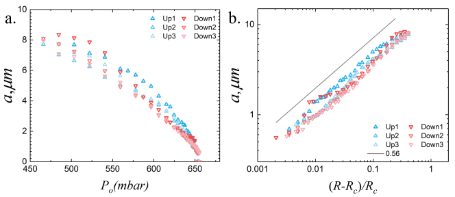
By inverting the flow direction of the oil, we now report results for the novel opposed flow geometry, in which the angle between the aqueous flow channel and the oil flow channel is 165∘. In Fig. 6(a) we show the jet radius for three cycles of increasing jet radius and decreasing jet radius. This time, the inner oil phase pressure was fixed at mbar, while the outer pressure was varied. Hence during the “up” phase, is decreased so as to increase , while during the “down” phase is increased. In the opposed flow geometry, there is very little hysteresis, and there is a much better collapse of the data across the three cycles of varying the outer pressure. This is even clearer in the log-log plot of Fig. 6(b), where for each cycle and for each direction of increasing and decreasing , we fitted the data to the power law (1). With the critical value in hand, we plotted against the critical pressure parameter .
There is now little variation of the slope in each case; in the “up” direction we obtain values , in the “down” direction . Fitting to the data for all three cycles leads to an average exponent of , shown as the straight line in Fig. 6(b). The smallest jets produced in the opposed flow geometry have a radius of about 0.5m, significantly smaller than anything produced by conventional focusing, see Table 1. One example of collected droplets from the device was characterized under the confocal microscope and is shown in Fig. 7(a), with mean radius of 1.2m. We were unable to determine whether there remained a small discontinuity as the jet disappears, or whether our ability to produce a small jet is limited by the accuracy with which the outer pressure can be adjusted. Most importantly, in the opposed flow geometry we no longer see a dripping state, but we pass directly from a jetting state to a state of no flow.
III.3 Droplet clusters
Since the jet decays into droplets further downstream, the very thin jets produced in the opposed flow geometry allow us to make correspondingly smaller droplets, with hydroxy ethyl cellulose polymers added to them. Owing to the short-range depletion attractions induced by HEC polymers, colloidal droplets with mean radius of 1.5 m form clusters, as shown in the confocal images of Fig. 7(b)-(e). These enable studies in the same spirit as meng2010 , but with 3d imaging, as the system is refractive index matched. In Figs. 7(b)-(e) we show closeups of individual clusters with particles; the wireframe inserts indicate the geometry of the cluster.

Our new model system enables the study of near-frictionless droplets. Unlike systems with solid particles, where access to the thermodynamic ground state is often suppressed klix2013 ; royall2018thunderbox , perhaps due to the polymer stabilizer layer thickness being the same size as the depletion polymers prasad2003 , these near-frictionless droplets may be better able to reach the ground state. The potential to generate smaller droplets with this method further enables us to form clusters with less tendency to sediment, and which may explore their configuration space very quickly, as the colloid diffusion time scales with the cube of the diameter. With a higher volume fraction of droplets, percolating colloidal gels can be obtained through the same depletion mechanism zaccarelli2007 ; manley2005 ; griffiths2017 .
IV Conclusions
In conclusion, it remains difficult to make sub 10 m droplets using conventional microfluidic methods, particularly in the case of oil-in-water systems. Instead, we have described a method to make colloidal oil droplets by tuning close to a second order transition, thereby reducing the droplet size by almost an order of magnitude. This was achieved by simply reversing the direction of the oil flow. If one succeeds in coming even closer to the transition, our approach has the potential of reducing droplet size practically without limit. We demonstrate the utility of the droplets produced here via the production of colloidal clusters, an experimental system which is challenging to access otherwise.
Acknowledgements.
J.D. acknowledges Bayer CropScience AG for financial support. M.M. acknowledges the EPSRC Doctoral training allowance EP/L504919/1, CPR acknowledges the Royal Society and Kyoto University SPIRITS fund, J.D. and CPR acknowledge the European Research Council (ERC consolidator grant NANOPRS, project number 617266) for financial support. J.E. acknowledges support from the Leverhulme Trust through International Academic Fellowship IAF-2017-010. He also gratefully acknowledges discussions with J.K. Nunes, as well as helpful comments on the manuscript.References
- [1] Ashleigh B Theberge, Fabienne Courtois, Yolanda Schaerli, Martin Fischlechner, Chris Abell, Florian Hollfelder, and Wilhelm TS Huck. Microdroplets in microfluidics: an evolving platform for discoveries in chemistry and biology. Angew. Chem. Int. Ed., 49(34):5846–5868, 2010.
- [2] C. Martino and Andrew J. deMello. Droplet-based microfluidics for artificial cell generation : a brief review. Interface Focus, 6:20160011, 2016.
- [3] David J Beebe, Glennys A Mensing, and Glenn M Walker. Physics and applications of microfluidics in biology. Annu. Rev. Biomed. Eng., 4:261–286, 2002.
- [4] Mira T. Guo, Assaf Rotem, John A. Heyman, and David A. Weitz. Droplet microfluidics for high-throughput biological assays. Lab Chip, 12(12):2146, 2012.
- [5] Changqing Yi, Cheuk Wing Li, Shenglin Ji, and Mengsu Yang. Microfluidics technology for manipulation and analysis of biological cells. Anal. Chim. Acta, 560(1-2):1–23, 2006.
- [6] Emmanuel Delamarche, David Juncker, and Heinz Schmid. Microfluidics for processing surfaces and miniaturizing biological assays. Adv. Mater., 17(24):2911–2933, 2005.
- [7] Max Meissner, Jun Dong, Jens Eggers, Annela M. Seddon, and C. Patrick Royall. Oil-in-water microfluidics on the colloidal scale: new routes to self-assembly and glassy packings. Soft Matter, 13:788–794, 2017.
- [8] Nicolas Champagne, Romain Vasseur, Adrien Montourcy, and Denis Bartolo. Traffic jams and intermittent flows in microfluidic networks. Phys. Rev. Lett., 105(4):044502, 2010.
- [9] T. Thorsen, R. W. Roberts, F. H. Arnold, and S. R. Quake. Dynamic pattern formation in a vesicle-generating microfluidic device. Phys. Rev. Lett., 86(18):4163–4166, 2001.
- [10] A. M. Gañán-Calvo and J. M. Gordillo. Perfectly monodisperse microbubbling by capillary flow focusing. Phys. Rev. Lett., 87(27 Pt 1):274501, 2001.
- [11] S. L. Anna, N. Bontoux, and H. A. Stone. Formation of dispersions using ”flow focusing” in microchannels. Appl. Phys. Lett., 82(3):364–366, 2003.
- [12] P. Garstecki, H. A. Stone, and G. M. Whitesides. Mechanism for Flow-Rate Controlled Breakup in Confined Geometries: A Route to Monodisperse Emulsions. Phys. Rev. Lett., 94(16):164501, 2005.
- [13] Takasi Nisisako, Toru Torii, and Toshiro Higuchi. Droplet formation in a microchannel network. Lab Chip, 2(1):24–26, 2002.
- [14] Takasi Nisisako, Shingo Okushima, and Toru Torii. Controlled formulation of monodisperse double emulsions in a multiple-phase microfluidic system. Soft Matter, 1(1):23–27, 2005.
- [15] Martin F Haase and Jasna Brujic. Tailoring of high-order multiple emulsions by the liquid–liquid phase separation of ternary mixtures. Angew. Chem. Int. Ed., 53(44):11793–11797, 2014.
- [16] W. A. C. Bauer, J. Kotar, P. Cicuta, R. T. Woodward, J. V. M. Weaver, and W. T. S. Huck. Microfluidic production of monodisperse functional o/w droplets and study of their reversible pH dependent aggregation behavior. Soft Matter, 7(9):4214–4220, 2011.
- [17] Céline Cohen, R. Giles, V. Sergeyeva, N. Mittal, P. Tabeling, D. Zerrouki, J. Baudry, J. Bibette, and N. Bremond. Parallelised production of fine and calibrated emulsions by coupling flow-focusing technique and partial wetting phenomenon. Microfluid Nanofluidics, 17:959–966, 2014.
- [18] DR Link, Shelley L Anna, DA Weitz, and HA Stone. Geometrically mediated breakup of drops in microfluidic devices. Phys. Rev. Lett., 92(5):054503, 2004.
- [19] Woong Chan Jeong, Jong Min Lim, Jae Hoon Choi, Jong Hoon Kim, You Jin Lee, Seung Hyun Kim, Gaehang Lee, Jong Duk Kim, Gi Ra Yi, and Seung Man Yang. Controlled generation of submicron emulsion droplets via highly stable tip-streaming mode in microfluidic devices. Lab Chip, 12(8):1446–1453, 2012.
- [20] Alfonso M. Gañán-Calvo, Román González-Prieto, Pascual Riesco-Chueca, Miguel A. Herrada, and María Flores-Mosquera. Focusing capillary jets close to the continuum limit. Nat. Phys., 3(10):737–742, 2007.
- [21] A. M. Gañán-Calvo. Cone-jet analytical extension of taylor’s electrostatic solution and the asymptotic universal scaling laws in electrospraying. Phys. Rev. Lett., 79:217–220, 1997.
- [22] M. A. Herrada, J. M. López-Herrera, A. M. Gañán-Calvo, E. J. Vega, J. M. Montanero, and S. Popinet. Numerical simulation of electrospray in the cone-jet mode. Phys. Rev. E, 86:026305, 2012.
- [23] G.I. Taylor. The formation of emulsions in definable fields of flow. Proceedings of the Royal Society, 29(Society, The Royal Society, Royal Sciences, Physical):71, 1934.
- [24] R. Suryo and O. A. Basaran. Tip streaming from a liquid drop forming from a tube in a co-flowing outer fluid. Phys. Fluids, 18:082102, 2006.
- [25] E Castro-Hernández, F Campo-Cortés, and José Manuel Gordillo. Slender-body theory for the generation of micrometre-sized emulsions through tip streaming. J. Fluid Mech., 698(2012):423–445, 2012.
- [26] S. L. Anna. Droplets and bubbles in microfluidic devices. Ann. Rev. Fluid Mech., 48:285–309, 2016.
- [27] J. Eggers and E. Villermaux. Physics of liquid jets. Rep. Progr. Phys., 71:036601, 2008.
- [28] Itai Cohen and Sidney R Nagel. Scaling at the selective withdrawal transition through a tube suspended above the fluid surface. Phys. Rev. Lett., 88(7):074501, 2002.
- [29] Sarah C. Case and Sidney R. Nagel. Spout states in the selective withdrawal of immiscible fluids through a nozzle suspended above a two-fluid interface. Phys. Rev. Lett., 98(11):114501, 2007.
- [30] Andrew S Utada, Alberto Fernandez-Nieves, Howard A Stone, and David A Weitz. Dripping to jetting transitions in coflowing liquid streams. Phys. Rev. Lett., 99(9):094502, 2007.
- [31] J.-M. Chomaz. Global instabilities in spatially developing flows: non-normality and nonlinearity. Annu. Rev. Fluid Mech., 37:357–392, 2005.
- [32] A. S. Utada, A. Fernandez-Nieves, J. M. Gordillo, and D. A. Weitz. Absolute instability of a liquid jet in a coflowing stream. Phys. Rev. Lett., 100:014502, 2008.
- [33] A. Malins, S. R. Williams, J. Eggers, and C. P. Royall. Identification of structure in condensed matter with the topological cluster classification. J. Chem. Phys., 139(23):234506, 2013.
- [34] A. Malins, S. R. Williams, J. Eggers, H. Tanaka, and C. P. Royall. Geometric frustration in small colloidal clusters. J. Phys.: Condens. Matter, 21:425103, 2009.
- [35] Guangnan Meng, Natalie Arkus, Michael P Brenner, and Vinothan N Manoharan. The free-energy landscape of clusters of attractive hard spheres. Science, 327(5965):560–563, 2010.
- [36] C. L. Klix, K. Murata, H. Tanaka, S. Williams, A. Malins, and C. P. Royall. Novel kinetic trapping in charged colloidal clusters due to self-induced surface charge organization. Sci. Rep., 3:2072, 2013.
- [37] W. A. C. Bauer, M. Fischlechner, C. Abell, and W. T. S. Huck. Hydrophilic PDMS microchannels for high-throughput formation of oil-in-water microdroplets and water-in-oil-in-water double emulsions. Lab Chip, 10(14):1814, 2010.
- [38] C. Carnero Ruiz, L. Díaz-López, and J. Aguiar. Micellization of sodium dodecyl sulfate in glycerol aqueous mixtures. J. Dispersion Sci. Technol., 29:266–273, 2008.
- [39] C. P. Royall. Hunting mermaids in real space: Known knowns, known unknowns and unknown unknowns. submitted, 2018.
- [40] V. Prasad, V. Trappe, A. D. Dinsmore, P. N. Segre, L. Cipelletti, and D. A. Weitz. Universal features of the fluid to solid transition for attractive colloidal particles. Faraday Discuss., 123:1–12, 2003.
- [41] E. Zaccarelli. Colloidal gels: Equilibrium and non-equilibrium routes. J. Phys.: Condens. Matter, 19:323101, 2007.
- [42] S. Manley, J. M. Skotheim, L. Mahadevan, and D. A. Weitz. Gravitational collapse of colloidal gels. Phys. Rev. Lett., 94(21):218302, 2005.
- [43] S. Griffiths, F. Turci, and C. P. Royall. Local structure of percolating gels at very low volume fractions. J. Chem. Phys., 146:014905, 2017.