Fundamental cavity–waveguide interplay in cavity QED
Abstract
Interfacing solid-state emitters with photonic structures is a key strategy for developing highly efficient photonic quantum technologies. Such structures are often organised into two distinct categories: nanocavities and waveguides. However, any realistic nanocavity structure simultaneously has characteristics of both a cavity and waveguide, which is particularly pronounced when the cavity is constructed using low-reflectivity mirrors in a waveguide structure with good transverse light confinement. In this regime, standard cavity quantum optics theory breaks down, as the waveguide character of the underlying dielectric is only weakly suppressed by the cavity mirrors. By consistently treating the photonic density of states of the structure, we provide a microscopic description of an emitter including the effects of phonon scattering over the full transition range from waveguide to cavity. This generalised theory lets us identify an optimal regime of operation for single-photon sources in optical nanostructures, where cavity and waveguide effects are concurrently exploited.
Solid-state emitters in photonic nanostructures play an important role in quantum optics and photonic quantum technologies O’Brien et al. (2009); Kok et al. (2007); Aharonovich et al. (2016), both as single-photon sources Varnava et al. (2008), and more generally as light-matter interfaces Arnold et al. (2015); Hu et al. (2008). Such nanostructures can be divided into two generic classes: Nanocavities work by enhancing spontaneous emission into a well-defined cavity mode through the Purcell effect Purcell (1946), while simultaneously suppressing decoherence mechanisms He et al. (2013); Ding et al. (2016); Somaschi et al. (2016); Kaer et al. (2013); Iles-Smith et al. (2017); Grange et al. (2017). Waveguides exploit slow-light effects in photonic crystal line defects Arcari et al. (2014); Manga Rao and Hughes (2007); Lecamp et al. (2007) or screening effects in e.g. nanowires Claudon et al. (2010); Reimer et al. (2012), such that spontaneous emission occurs preferentially into the desired channel, thus achieving high efficiencies over a broad frequency range. These two classes of structures are treated very differently in standard quantum optics theory. Nanocavities are often modelled using a standard Jaynes-Cummings treatment, where the electric field in the cavity is quantised as a single optical mode Jaynes and Cummings (1963), while waveguides are modelled as an unstructured reservoir with a continuum of optical modes with little or no spectral variation Weisskopf and Wigner (1930). This is a problem in the regime of strongly dissipative cavities, where neither of the two models provide a good physical description.
To illustrate this point, consider a cavity embedded in a waveguide structure defined by mirrors with variable reflectivity (Fig. 1a). If the reflectivity of the mirrors is decreased, intuitively one would expect a smooth transition between a strongly localised single-mode cavity, to a standard broadband photonic waveguide, with an intermediate regime at low factors, where the optical density of states simultaneously exhibits characteristics of both a waveguide and cavity Ismail et al. (2016); Kristensen and Hughes (2013); Lalanne et al. ; Barnett and Radmore (1988). However, the Jaynes-Cummings model does not demonstrate this behaviour, failing to describe the properties of emitters in either a waveguide or bulk medium for vanishing factors.
In this paper, we present a quantum optical model that captures the transition between a high- cavity and a waveguide, allowing consistent treatment of waveguides, lossy resonators and high quality cavities. Our model constitutes a bridge between highly accurate optical simulations of nanostructures de Lasson et al. (2018) and microscopic quantum dynamical calculations. This way, the quantum properties of generated light can be calculated, while fully accounting for the electromagnetic properties of the nanostructure. The generality of this theory enables us to identify an optimal regime of operation for quantum dot single-photon sources, which simultaneously harnesses the high efficiency of a waveguide and the phonon-suppressing spectral structure of a cavity.
We shall consider a two-level emitter placed in a waveguide with two mirrors forming a Fabry-Pérot cavity (Fig. 1a). We denote the ground and excited states of the emitter by and , respectively, separated by the transition frequency . The electromagnetic field can be described by a set of modes with annihilation and creation operators, and , frequencies and emitter coupling strengths . The Hamiltonian governing the entire system takes the form , where and are the Hamiltonians governing the emitter, electromagnetic field and their interaction, respectively. In the rotating wave approximation, they take the standard forms (): , , and , with . The indices labelling the optical modes can be divided into two sets: the first set, , contains all the modes with a certain transverse field profile of interest, for example that of the fundamental waveguide mode; the second set, , accounts for non-guided radiation modes, and guided modes with different transverse field profile if the structure is not single-moded. Each mode set has an associated local density of states (LDOS),
| (1) |
In the absence of mirrors in the waveguide, both densities can be considered constant over a large frequency range, , where is the spontaneous emission rate of the emitter into the mode set (cf. Fig. 1b). However, when mirrors with amplitude reflectivities are added to the structure, becomes Gregersen et al. (2016)
| (2) |
where is the emission rate into the waveguide in the absence of mirrors, which is highly dependent on the local field strength and position of the emitter. The phase accumulated during propagation in the cavity is given by the effective complex reflectivity coefficient , where is a mirror reflection phase, is the cavity length, and we assume a dispersion-less propagation factor, , where is the effective refractive index of the waveguide mode. For simplicity, we have assumed that the emitter is placed in the middle of the cavity. Further, since the mirror reflection phase only amounts to a shift in resonance and the position of the field antinodes in the cavity, they may be safely neglected.
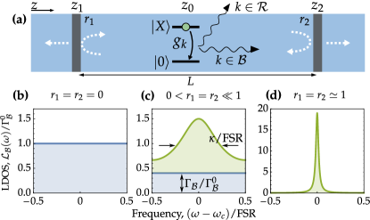
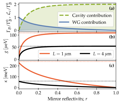
Importantly, for intermediate reflectivities, the LDOS features a Lorentzian lineshape offset by a constant background Gregersen et al. (2016), as shown in Fig. 1c, where (2) is plotted for . The background contribution to the LDOS, , stems from the waveguide nature of the dielectric structure, while the Lorentzian peak is a signature of the cavity quasi-mode, which becomes the dominant contribution to the LDOS as (cf. Fig 1d). To separate these two contributions from each other, we approximate the LDOS, (2), as , where we have introduced the dimensionless frequency and linewidth, . The LDOS weights and determine the contributions from background waveguide modes and the cavity, respectively. In the Supplemental Information (SI), we show how the mirror reflectivities and , and the bare waveguide emission rate uniquely determine all three parameters , and . Furthermore, , , and determine the emitter–cavity coupling strength, .
In Fig. 2a, the contribution to the LDOS from waveguide background modes and the cavity quasimode is shown as functions of the mirror reflectivity for a symmetric cavity (). These depend solely on the mirror reflectivity and show clearly how the system is gradually transformed from a waveguide for , to a cavity with full suppression of the waveguide background as . Similarly, the variation of the emitter–cavity coupling strength is shown in Fig. 2b. While is normally assumed to depend only on the cavity mode volume, , we see here that as , since the cavity does not contribute to the LDOS in this limit. As the reflectivity increases, approaches the value (dotted lines in Fig. 2b). This is consistent with the conventional scaling of as , noting that with the transverse mode area. Fig. 2c shows how the cavity linewidth tends to zero as the mirror reflectivity is increased. Importantly, the linewidth does not diverge as , but rather approximately converges to the value (dotted lines in Fig. 2c), which is the inverse of the time it takes for light to propagate from the middle of the cavity to one of the mirrors Manga Rao and Hughes (2007).
From these parameters, we are able to derive a quantum optical master equation to describe the dynamical and optical properties of the emitter (see SI for details),
| (3) | ||||
where () is the annihilation (creation) operator for the cavity mode, and is the Lindblad dissipator.
In the vanishing mirror limit, , we have , and the master equation reduces to the usual waveguide case. Conversely, in the high reflectivity limit, , the waveguide contribution to the LDOS vanishes, and the master equation describes an emitter coupled to a cavity quasimode and a radiation bath.
If the waveguide structure is single-moded, the emission rate only accounts for emission into radiation modes out of the waveguide structure, and it can be taken independent of the mirror reflectivity, . However, if the structure is multi-moded, also accounts for emission into waveguide modes with different transverse field distribution than . The cavity mirrors also modulate the LDOS for these modes, such that the total LDOS of the radiation reservoir, , becomes
| (4) |
where is the emission rate into radiation modes and the sum runs over all other mode families in the waveguide, except for the mode of interest. In the absence of cavity mirrors, we have the spontaneous emission rate, , and complex reflectivity, , associated to the mode, where is the corresponding propagation constant. Presuming that the emitter is only resonant with the mode of interest, we can assume weak coupling to the remaining modes, such that the emitter decay into is simply described by the spontaneous emission rate .
We now apply our formalism to the case of a quantum dot (QD) single-photon source in a dielectric waveguide structure with mirrors, taking scattering with longitudinal acoustic phonons into account. We take one cavity mirror to be perfectly reflecting and the other to have a finite reflectivity, . Due to interference effects, the presence of a perfectly reflecting mirror modulates the LDOS by a sinusoidal variation with a period of the free spectral range, , even in the limit . If the frequency range of interest is appreciably smaller than this range, as is often the case for a QD in a nanocavity, we find that the effect of the perfect bottom mirror can be implemented by using the renormalised rates, and , where and are calculated assuming a symmetric cavity as in Fig. 2. This means that in the limit of a vanishing front mirror reflectivity, the renormalised factor in the presence of the back mirror is . Here, is the waveguide factor in the absence of both mirrors, not to be confused with the wave propagation constant. Furthermore, we assume that the underlying waveguide structure is single-moded such that can be considered constant.
The total Hamiltonian of the system is given by , with and the free phonon and emitter–phonon Hamiltonians, given by Mahan (2013); Ramsay et al. (2010)
| (5) |
where () is the annihilation (creation) operator for the phonon mode with wavevector , with associated frequency , and exciton coupling strength . The phononic spectral density is given by , where is the exciton–phonon coupling parameter and the cutoff frequency Nazir and McCutcheon (2016). To calculate the dynamics and account for non-Markovian phonon relaxation, we make use of the polaron theory McCutcheon and Nazir (2010); McCutcheon et al. (2011); Roy and Hughes (2011); Wilson-Rae and Imamoğlu (2002); Nazir and McCutcheon (2016); Iles-Smith et al. (2017). This is done by first applying the unitary transformation to the Hamiltonian, , where . In this frame, an equation of motion for the reduced state of the QD that is non-perturbative in the electron-phonon coupling strength may be derived (see SI for details). For completeness, we also include a pure dephasing process Grange et al. (2017) with rate , which accounts for dephasing from charge noise Thoma et al. (2016), spin noise and virtual electron–phonon scattering Muljarov and Zimmermann (2004); Reigue et al. (2017).
The indistinguishability of photons emitted from the QD into detected modes Kiraz et al. (2004); Iles-Smith et al. (2017) can be calculated using tools from optical theory Novotny and Hecht (2012); Wubs et al. (2004), as discussed in the SI. This leads to
| (6) |
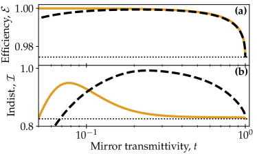
where accounts for the cavity filtering, is the total power in the modes, and is the two-colour dipole spectrum. The two-colour spectrum may be separated into two contributions , where describes emission into a sharp zero-phonon line (ZPL) from direct exciton relaxation, and corresponds to a broad phonon sideband (PSB) where a phonon and a photon are simultaneously emitted. Centrally, the Franck-Condon factor, , is the fraction of photons emitted into the ZPL, if the electromagnetic LDOS is frequency independent Iles-Smith et al. (2017). Here, , where is the temperature and is the Boltzmann constant. The efficiency is defined as the ratio of energy emitted into the desired waveguide mode and the total emitted energy. It is calculated as , where . In Fig. 3, the efficiency and indistinguishability are plotted versus transmittivity of the finitely reflecting cavity mirror for identical waveguide structures with cavity lengths (solid) and (dashed), where is the QD transition wavelength, taken as . For clarity, has been set to 0.
In the weak emitter–cavity coupling regime, the cavity resonance is broad compared to the ZPL, but can still vary appreciably over the PSB, meaning phonon-assisted QD relaxation is suppressed and the ZPL is Purcell enhanced. In this parameter regime, we may generalise the results of Ref. Iles-Smith et al. (2017) to obtain analytical expressions taking into account the waveguide–cavity interplay,
| (7) | ||||
| (8) |
where is the fraction of the PSB not removed by filtering imposed by the electromagnetic LDOS, is a phonon-enhanced pure dephasing rate and . In the limit , (8) reduces to , meaning the efficiency converges towards , as the front mirror is gradually removed (black dotted line in Fig. 3a). If the waveguide mode contribution to the LDOS were ignored, the efficiency would approach zero as Iles-Smith et al. (2017), which is only a valid approximation when the underlying waveguide structure has a vanishing factor. In the absence of pure dephasing, , (7) gives (black dotted line in Fig. 3b) as , consistent with Ref. Iles-Smith et al. (2017).
Contrarily, in the strong emitter–cavity coupling regime, , the cavity and exciton hybridise and form a polariton pair. In this case, the phonons drive incoherent transitions between the two polaritons, leading to a decreased photon indistinguishability. To resolve this effect, quantisation of the cavity becomes crucial, and a semi-classical weak light-matter coupling theory is insufficient. As seen in Fig. 3b, increasing the cavity length leads to a smaller , which allows further narrowing of the cavity line and thus suppression of the phonon sideband without entering the strong coupling regime, due to a larger cavity mode volume. Since the underlying waveguide structure has a high factor, the efficiency does not suffer noticeably from this. The efficiency starts to decrease when becomes small enough that the photon escapes the cavity by scattering to radiation modes via the QD rather than dissipating through the mirror. Increasing the cavity length will continue to improve the coherence of emitted photons until the cavity free spectral range becomes comparable to the width of the PSB, which will then become Purcell enhanced. For typical QDs, the PSB extends over a few meV, and the cavity would need a length of for this effect to set in.
In conclusion, we have characterised the important role of weakly suppressed waveguide modes in nanocavities. As a demonstration of this, we have shown that long nanocavities based on high factor waveguides constitute a promising new route to high-performance single photon sources.
Acknowledgements.
E.V.D, J.I.S., and J.M. acknowledge funding from the Danish Council for Independent Research (Grant No. DFF-4181-00416) and from Villum Fonden (Grant 8692). J.I.S is supported by the Engineering and Physical Sciences Research Council, Grant No. EP/N008154/1. N.G and A.D.O. acknowledge support from the Danish National Research Council for Technology and Production (LOQIT Sapere Aude grant DFF # 4005-00370).References
- O’Brien et al. (2009) J. L. O’Brien, A. Furusawa, and J. Vučković, Nat. Phot. 3, 687 (2009).
- Kok et al. (2007) P. Kok, W. J. Munro, K. Nemoto, T. C. Ralph, J. P. Dowling, and G. J. Milburn, Rev. Mod. Phys. 79, 135 (2007).
- Aharonovich et al. (2016) I. Aharonovich, D. Englund, and M. Toth, Nat. Phot. 10, 631 (2016).
- Varnava et al. (2008) M. Varnava, D. E. Browne, and T. Rudolph, Phys. Rev. Lett. 100, 060502 (2008).
- Arnold et al. (2015) C. Arnold, J. Demory, V. Loo, A. Lemaître, I. Sagnes, M. Glazov, O. Krebs, P. Voisin, P. Senellart, and L. Lanco, Nat. Comms. 6, 6236 (2015).
- Hu et al. (2008) C. Y. Hu, A. Young, J. L. O’Brien, W. J. Munro, and J. G. Rarity, Physical Review B 78, 085307 (2008).
- Purcell (1946) E. M. Purcell, Phys. Rev. 69, 681+ (1946).
- He et al. (2013) Y.-M. He, Y. He, Y.-J. Wei, D. Wu, M. Atatüre, C. Schneider, S. Höfling, M. Kamp, C.-Y. Lu, and J.-W. Pan, Nature nanotechnology 8, 213 (2013).
- Ding et al. (2016) X. Ding, Y. He, Z.-C. Duan, N. Gregersen, M.-C. Chen, S. Unsleber, S. Maier, C. Schneider, M. Kamp, S. Höfling, et al., Phys. Rev. Lett. 116, 020401 (2016).
- Somaschi et al. (2016) N. Somaschi, V. Giesz, L. De Santis, J. Loredo, M. P. Almeida, G. Hornecker, S. L. Portalupi, T. Grange, C. Antón, J. Demory, et al., Nat. Phot. 10, 340 (2016).
- Kaer et al. (2013) P. Kaer, P. Lodahl, A.-P. Jauho, and J. Mork, Physical Review B 87, 081308 (2013).
- Iles-Smith et al. (2017) J. Iles-Smith, D. P. S. McCutcheon, A. Nazir, and J. Mørk, Nat. Phot. 11, 521 (2017).
- Grange et al. (2017) T. Grange, N. Somaschi, C. Antón, L. De Santis, G. Coppola, V. Giesz, A. Lemaître, I. Sagnes, A. Auffèves, and P. Senellart, Phys. Rev. Lett. 118, 253602 (2017).
- Arcari et al. (2014) M. Arcari, I. Söllner, A. Javadi, S. L. Hansen, S. Mahmoodian, J. Liu, H. Thyrrestrup, E. H. Lee, J. D. Song, S. Stobbe, et al., Phys. Rev. Lett. 113, 093603 (2014).
- Manga Rao and Hughes (2007) V. S. C. Manga Rao and S. Hughes, Physical Review B 75, 205437 (2007).
- Lecamp et al. (2007) G. Lecamp, P. Lalanne, and J. P. Hugonin, Phys. Rev. Lett. 99, 023902 (2007).
- Claudon et al. (2010) J. Claudon, J. Bleuse, N. S. Malik, M. Bazin, P. Jaffrennou, N. Gregersen, C. Sauvan, P. Lalanne, and J.-M. Gérard, Nat. Phot. 4, 174 (2010).
- Reimer et al. (2012) M. E. Reimer, G. Bulgarini, N. Akopian, M. Hocevar, M. B. Bavinck, M. A. Verheijen, E. P. Bakkers, L. P. Kouwenhoven, and V. Zwiller, Nat. Comms. 3, 737 (2012).
- Jaynes and Cummings (1963) E. T. Jaynes and F. W. Cummings, Proceedings of the IEEE 51, 89 (1963).
- Weisskopf and Wigner (1930) V. Weisskopf and E. Wigner, Zeitschrift für Physik 63, 54 (1930).
- Ismail et al. (2016) N. Ismail, C. C. Kores, D. Geskus, and M. Pollnau, Optics Express 24, 16366 (2016).
- Kristensen and Hughes (2013) P. T. Kristensen and S. Hughes, ACS Photonics 1, 2 (2013).
- (23) P. Lalanne, W. Yan, K. Vynck, C. Sauvan, and J.-P. Hugonin, Laser & Photonics Reviews 0, 1700113.
- Barnett and Radmore (1988) S. Barnett and P. Radmore, Optics Communications 68, 364 (1988).
- de Lasson et al. (2018) J. R. de Lasson, L. H. Frandsen, P. Gutsche, S. Burger, O. S. Kim, O. Breinbjerg, A. Ivinskaya, F. Wang, O. Sigmund, T. Häyrynen, et al., Optics Express 26, 11366 (2018).
- Gregersen et al. (2016) N. Gregersen, D. P. S. McCutcheon, J. Mørk, J.-M. Gérard, and J. Claudon, Optics express 24, 20904 (2016).
- Mahan (2013) G. D. Mahan, Many-particle physics (Springer Science & Business Media, 2013).
- Ramsay et al. (2010) A. J. Ramsay, T. M. Godden, S. J. Boyle, E. M. Gauger, A. Nazir, B. W. Lovett, A. M. Fox, and M. S. Skolnick, Phys. Rev. Lett. 105, 177402 (2010).
- Nazir and McCutcheon (2016) A. Nazir and D. P. S. McCutcheon, Journal of Physics: Condensed Matter 28, 103002 (2016).
- McCutcheon and Nazir (2010) D. P. S. McCutcheon and A. Nazir, New Journal of Physics 12, 113042 (2010).
- McCutcheon et al. (2011) D. P. S. McCutcheon, N. S. Dattani, E. M. Gauger, B. W. Lovett, and A. Nazir, Physical Review B 84, 081305 (2011).
- Roy and Hughes (2011) C. Roy and S. Hughes, Physical Review X 1, 021009 (2011).
- Wilson-Rae and Imamoğlu (2002) I. Wilson-Rae and A. Imamoğlu, Physical Review B 65, 235311 (2002).
- Thoma et al. (2016) A. Thoma, P. Schnauber, M. Gschrey, M. Seifried, J. Wolters, J.-H. Schulze, A. Strittmatter, S. Rodt, A. Carmele, A. Knorr, T. Heindel, and S. Reitzenstein, Phys. Rev. Lett. 116, 033601 (2016).
- Muljarov and Zimmermann (2004) E. A. Muljarov and R. Zimmermann, Phys. Rev. Lett. 93, 237401 (2004).
- Reigue et al. (2017) A. Reigue, J. Iles-Smith, F. Lux, L. Monniello, M. Bernard, F. Margaillan, A. Lemaitre, A. Martinez, D. P. S. McCutcheon, J. Mørk, et al., Phys. Rev. Lett. 118, 233602 (2017).
- Kiraz et al. (2004) A. Kiraz, M. Atatüre, and A. Imamoğlu, Physical Review A 69, 032305 (2004).
- Novotny and Hecht (2012) L. Novotny and B. Hecht, Principles of nano-optics (Cambridge university press, 2012).
- Wubs et al. (2004) M. Wubs, L. G. Suttorp, and A. Lagendijk, Physical Review A 70, 053823 (2004).