High energy Free Electron Laser for nuclear applications
Abstract
The capability of Free-Electron Lasers to generate photon beams with record performances in the domain of MeV-class photon energy for nuclear photonics applications is here analyzed. We discuss possible nuclear FEL working points. Some typical situations are presented and simulated by means of the three-dimensional code GENESIS 1.3. The losses by spontaneous emission and by wakefield induced energy spread are then evaluated. The calculations show the possibility of generating FEL radiation at 1-4 MeV with less than 300 eV of bandwidth with not prohibitive set up requirements, achieving therefore regimes where no other kind of gamma ray sources could arrive.
I Introduction
Present X-ray Free-Electron Lasers (FELs) in operation or under commissioning achieve maximum photon energies between 10-20 keV LCLS ; SCSS ; XFEL ; PSI , a range covering an extremely wide number of applications in the imaging field and in the atomic and electronic physics. For larger photon energies, entering therefore the Nuclear Photonics domain, which starts at around 1 MeV and extends up to several MeVs, the radiation sources of reference at the state of art and for the near future developments are, at this moment, the Inverse Compton Scattering sources (ICSs)HIGS ; ELI . ICSs are based on the spontaneous incoherent radiation generated by Compton back-scattering of lasers by high brightness electron beams HIGS ; ELI and typically are projected to provide few polarized photons at 1-20 MeV in a bandwidth not narrower than several , namely 5-100 keV absolute bandwidth, with a completely incoherent radiation structure.
It has been debated whether a scientific case exists for FELs in this regime. Despite the large costs inherent in the development of Linac based FELs with electron beam in the range GeV, a strong scientific case justifies a design study within the frame of a Linear Collider scenario, i.e. conceiving a parasitic use for a nuclear oriented FEL of a separate beam line at a TeV-class Linac based collider. Using a superconducting linac XFEL in re-circulating mode by means of a return loop to double the energy to >30 GeV could also be an option. Although FELs were born and developed mainly with the goal to advance scientific researches and knowledge in the science of matter and related fields, by delivering the most advanced coherent and bright X-ray photon beams, it is worthwhile to consider exploiting their extreme capabilities to generate photon beams with record performances also in the domain of MeV-class photon energy. The coherent and cooperative mechanism for emitting radiation proper of FELs allows for a large upgrade of the photon beam properties if the FEL collective instability can be operated up to such a high photon energy. Together with coherence and enhancement in the radiated power goes an extremely narrow bandwidth proper of FELs operation, approaching the range of O() for the rms relative bandwidth, compared to the aforementioned O() of ICSs. This is extremely crucial for Nuclear Photonics applications, in which bandwidth, as well as spectral density, are of the maximum relevance. The achievement of absolute bandwidths down to the 100 eV range (relative bandwidth smaller than O() into the O() range) would open a completely new approach in Nuclear Photonics, enabling the excitation of single nuclear states, now forbidden to ICSs since their best performance is limited to more than two order of magnitude above this value. 100 eV absolute bandwidth would therefore represent a true breakthrough in Nuclear Physics and Photonics – the best energy resolution achieved with pure Ge detectors and close to the intrinsic single nuclear state bandwidth nucl . The next generation ICSs will probably be able to go down by one order of magnitude in relative bandwidth, approaching 1 keV, still far from the 100 eV level, the main issue being the collision laser intrinsic bandwidth, unlikely to become narrower than . The real challenge for nuclear oriented FELs will be the capability to operate below the O() bandwidth, implying severe requests to the accuracy and precision of undulator field stability and uniformity, as well as extremely low emittances and energy spreads of the electron beam.
In this paper, first we discuss the possible nuclear FEL working points. Then, some characteristic situations are presented and simulated by means of the FEL code GENESIS 1.3 genesis . The losses by spontaneous emission and by wakefield induced energy spread are then evaluated. We close with comments and conclusions.
II Working point discussion
The aim is to produce FEL radiation with energy larger than , with absolute bandwidth approaching (), with the least demanding requirements for undulator, electron beam current and energy.
The Pierce parameter key-1 , describing the one-dimensional FEL dynamics, can be expressed as:
| (1) |
where here in micron, is the undulator period, the undulator parameter and and gives an estimate of the natural FEL bandwidth Furthermore,
| (2) |
is the radiation resonant wavelength.
By combining (1) and (2) and considering the linear relation between undulator period and strength (being therefore with peak field of the magnets in a planar undulator), the nuclear FEL conditions can be written as:
| (3) |
with a corresponding photon energy:
| (4) |
For () and (), graphs of , and as functions of (whose state of the art is so far around half centimeter with und corti ; und corti2 ) for and and are presented in Fig. 1.
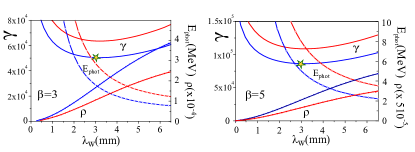
As can be seen, while the photon energy decreases monotonically, passes through a flat minimum at whose value is:
| (5) |
with a corresponding photon energy of:
| (6) |
Photon energies (> 1 MeV) and bandwidths ( approaching 1) suitable for nuclear applications are therefore obtained with current densities in the range:
| (7) |
and corresponding Pierce parameters:
| (8) |
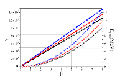
Values of around or slightly below the minimum of identify useful working points. Relying on Fig.1, lower periods lead to a favorable trend of the photon energy, but worse conditions in and , corresponding to longer undulators and less radiation photons. Going towards longer periods, instead, the parameter increases, but the energy of the radiation photons tends to go below the MeV level.
For (), situations with MeV can be obtained with mm and . With J=2000 , the parameter turns out to be about . It is possible to achieve similar bandwidth levels using lower current densities J=1000 , together with larger electron energies , with consequent increase in the photon energy MeV. In this case the FEL parameter does not exceed , leading to longer gain and saturation lengths and smaller gains. The case is characterized by larger electron and radiation photon energy with a consequent smaller , longer undulators and lower radiation yield.
These two working points are presented in Table 1.
| case A | case B | |
|---|---|---|
| 1.8 | 4.3 | |
| 300 | 500 | |
| E (GeV) | 25 | 40 |
| I (kA) | 12.5 | 12.5 |
| 2.5 | 2.5 | |
| 5 10-3-4 10-2 | 5 10-3-2.5 10-2 | |
| 0.5 10-4-10-4 | 0.5 10-4-10-4 | |
| 3 | 3 | |
| 0.42 | 0.42 | |
| 1.710-4 | 1.3 10-4 |
Regarding their feasibility, the state of the art of the undulators is so far at 4 mm of period with T, using the cryogenic technology und corti ; und corti2 . We are exploring therefore a regime not much far from this one. A superconducting helical undulator could be used to further reduce the gain length. The requirements on the electron beam will be commented in the next Section.
III Three-dimensional simulations
Three-dimensional time-dependent simulations have been performed with the code GENESIS 1.3 genesis for both working points described in Table 1, with varying electron emittance and energy spread and using the best numerical accuracy options. In these simulations, due to the low emittance and to the relatively short saturation length, the electron beam transverse dimensions have not be taken under control by any external focusing system. They increase therefore along the undulator from 2.5 to about 5 in the worst case, leading to slightly longer gain lengths and lower saturation power levels with respect to those evaluated with the initial values, but also slightly smaller bandwidths in those cases that are not strongly dominated by emittance and energy spread.
The results of the simulations are summarized in Fig. 3 (case A) and Fig. 4 (case B), where the bandwidth (a) and the number of photons (b) are reported as function of the emittance for two values of energy spread.
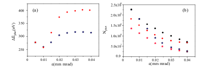
In case A, (, the bandwidth at very low emittance assumes values close to its one-dimensional natural value , and then increases with the emittance according to the trend given by the Ming Xie formulas key-2 . At the same time, the number of photons decreases from few to less than . The saturation length increases from 10-15 m at low emittance up to values larger than 30 m. In these cases we have reported in the graph and in the Table the value of the energy and number of photons at 30 m.
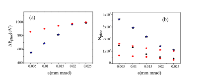
With further larger emittance, since the electron beam transverse dimension along the undulator increases with the emittance, the parameter becomes in average smaller, partially compensating the enlargement due to three-dimensional effects. The bandwidth therefore presents a plateau, with a subsequent decrease at increasing emittance. In case B, ( at null emittance the bandwidth shows a significant influence of the energy spread.
| e-beam energy | 0.31 GeV | absolute bandwidth | 17.5 keV |
| Period | 0.5 µm | norm. emitt. en (µm) | 0.5 |
| 0.02 | energy spread | 7. | |
| Photon energy | 3.5 MeV | repetition rate | 3.2 kHz |
| peak current | 200 A | average beam current | 800 nA |
| e- bunch charge | 250 pC | average beam power | 240 W |
| Laser energy | 0.2 J | # photons/pulse | |
| e- beam spot size | 20 µm | spectral density (s eV)-1 | 7.6 103 |
| relative bandwidth | 5.0 | div. angle | 40 µrad |
The absolute bandwidth is more than one order of magnitude narrower than ELI-NP-GBS (see Table 2), the number of photon per pulse is three order of magnitude larger, leading to spectral densities four order of magnitude higher. In Table 3, the simulation parameters and results of the FEL source are listed. As can be seen, at 20 pC, levels of electron emittance up to 4 mm mrad can be tolerated with energy spreads 0.5-1 , not too far from the state of the art reaching mm mrad and relative energy spread. Better beam quality requires further improvements in high-brilliance beam sources, which may also include plasma-wakefield driven injectors. In order to decrease further the bandwidth we need to relax the undulator parameter and/or the electron beam peak current (from tens kA down to few kA): this increases substantially the technological challenges on the beam quality (energy spread in particular) and undulator field quality and uniformity.
| case A | case B | |||||||
| e- beam energy (GeV) | 25 | 40 | ||||||
| Period (mm) | 3 | 3 | ||||||
| 0.35 | 0.35 | |||||||
| e- beam charge (pC) | 20 | 20 | ||||||
| e- beam length rms (fs) | 1 | 1 | ||||||
| e- beam initial spot size (µm) | 2.5 | 2.5 | ||||||
| Photon energy (MeV) | 1.85 | 4.2 | ||||||
| peak current (kA) | 12.5 | 12.5 | 12.5 | 12.5 | 12.5 | 12.5 | 12.5 | 12.5 |
| (µm) | 0.01 | 0.04 | 0.01 | 0.04 | 0.01 | 0.025 | 0.01 | 0.025 |
| slice energy spread x | 0.5 | 0.5 | 1 | 1 | 0.5 | 0.5 | 1 | 1 |
| initial x | 1.5 | 1.5 | 1.5 | 1.5 | 0.95 | 0.95 | 0.95 | 0.95 |
| 3d initial x | 1.2 | 0.47 | 0.95 | 0.4 | 0.7 | 0.45 | 0.42 | 0.3 |
| saturation length (m) | 15 | >30 | 22 | >30 | 24 | >30 | >30 | >30 |
| relative bandwidth x | 1.4 | 1.7 | 1.4 | 2.1 | 1.65 | 2.3 | 2.1 | 2.3 |
| absolute bandwidth (eV) | 260 | 320 | 260 | 400 | 690 | 990 | 900 | 990 |
| rad. energy/pulse (J) | 21 | 17 | 26 | 3∗ | 17∗ | 2.8∗ | ||
| # photons/pulse | 18.3 | 15. | 10. | |||||
| Spectral Density | 2.8 | 0.9 | 2.3 | 0.67 | 1.6 | 0.048 | 0.3 | 0.04 |
| phot. beam div. angle (rad) | 1 | 0.78 | 0.8 | 0.7 | 0.28 | 0.25 | 0.42 | 0.35 |
| radiation size(m) | 5 | 3 | 5.5 | 3.5 | 4 | 3.5 | 5 | 4 |
| Current limit for losses (A) | 1650 | 2240 | ||||||
| incoh. div. angle (µrad) | 25 | 10 |
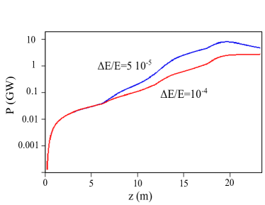
In Fig 5 we show the power growth as function of the undulator length, for case A with emittance and two values of energy spread. Saturation is achieved in 17-20 m, with power levels of 1-10 GW. The bandwidth achieves 260 eV, a bit less than the nominal value of 300 eV. The photon beam divergence angle is dominated by the electron dynamics.
IV Spontaneous undulator emission and wakefield induced energy spread losses
Possible sources of losses are the spontaneous undulator emission in the first undulator stages and the wakefiels induced energy spread. If the energy losses due to undulator spontaneous emission in the first FEL gain lengths are intense, the FEL process does not start. The spectral broadening due to the spontaneous emission can be estimated through a corresponding induced electron energy spread given by:
as derived in the Appendix, in agreement with the result of Ref [LCLS].
The coherent emission can occur only if the relative bandwidth enlargement due to this energy spread within the first gain length is less than the natural FEL bandwidth :
This can be translated into a condition for the current density:
In our cases, for both working points, the density current limits are lower than the value chosen.
As regards the electron energy spread induced by the wakefields, we have evaluated numerically the distortion in the electron distribution due to the wakefields during the propagation along the undulator, assuming a copper beam pipe with millimeter size and electron beams with the characteristics of the working points analyzed. Since the total charge is very small and the electron beam very short, the wakefield effect is completely negligible.
V Conclusions
The capability of Free-Electron Lasers to generate photon beams with record performances in the domain of MeV-class photon energy for nuclear photonics applications is here analyzed. We discuss possible nuclear FEL working points. Some typical situations are presented and simulated by means of GENESIS 1.3. The losses by spontaneous emission and by wakefield induced energy spread are then evaluated.
Appendix
Recalling the definition of undulator parameter , the total energy of the undulator field ( being the magnetic energy density, the transverse area, the undulator period and the undulator length), is:
| (9) |
The total photon number emitted in the spontaneous undulator radiation process can be estimated through the luminosity formula as:
| (10) |
where with m the classical electron radius, number of electron and number of the pseudophotons of the undulator.
Collecting (8) and (9), we have:
The electron distribution is given by the sum of the initial electron distribution and a perturbation due to the undulator:
where is fitted by:
with
Since we suppose that , we can assume that
The energy spread induced by the spontaneous emission is therefore:
Introducing the Compton wavelength m, we obtain:
in agreement with the result of Ref [LCLS,].
If this relative bandwidth enlargement within the first gain length is less than the natural FEL bandwidth, the coherent emission can occur. This can be translated into a condition for the current density:
or:
References
- (1) LCLS Design Study Report, SLAC-R-521 UC-414 (1998).
- (2) XFEL/SPring-8 Beamline Technical Design Report, XFEL/SPring-8 BL-TDR (2010).
- (3) SwissFEL Conceptual Design Report: https://www.psi.ch/swissfel/HomeEN/SwissFEL_CDR _web_ small.pdf
- (4) Winfried Decking and Hans Weise, ’Commissioning of the European XFEL Accelerator’, invited paper at IPAC 2017, Copenhagen.
- (5) O. Adriani et al., ’ELI-NP-GBS Technical Design Report’, http://arxiv.org/ftp/arxiv/papers/1407/1407.3669.pdf.
- (6) C. Sun and Y. K. Wu, ’Theoretical and simulation studies of characteristics of a Compton light source’, Phys. Rev. ST Accel. Beams 14, 044701 (2011).
- (7) C. W. Arnold,T. B. Clegg, C. Iliadis, H. J. Karwowski, G. C. Rich, and J. R. Tompkins, ’Cross-section measurement of 9Be( 8Be and implications for + n → 9Be in the r process’, Physical Review C 85, 044605 (2012)
- (8) S. Reiche, ’GENESIS 1.3: a fully 3D time-dependent FEL simulation code’, Nucl. Instrum. and Meth. in Phys. Res. A 429, 243 (1999).
- (9) R. Bonifacio, C. Pellegrini, and L. M. Narducci, ’Collective instabilities and high-gain regime in a free electron laser’, Opt. Commun. 50, 373 (1984).
- (10) Shigeru Yamamoto: ’Development of undulator magnets towards very short period lengths’ , AIP Conference Proceedings 1741, 020029 (2016); doi: 10.1063/1.4952808
- (11) J. Bahrdt, H.-J. Bäcker, M. Dirsatt, W. Frentrup, A. Gaupp, D. Just, D. Pflückhahn, M. Scheer, B. Schulz, R. Weingartner, F. Grüner, F. O’Shea, ’Cryogenic Design of a PrFeB-Based Uundulator’ Proceedings of IPAC’10, Kyoto, Japan WEPD012
- (12) Ming Xie, ’Design Optimixzation for an X-ray Free-Electron Laser driven by SLAC Linac’ Proceedings of PAC, (1995) DOI: 10.1109/PAC.1995.504603 .