Performing Fully Parallel Constraint Logic Programming on a Quantum Annealer
Abstract
A quantum annealer exploits quantum effects to solve a particular type of optimization problem. The advantage of this specialized hardware is that it effectively considers all possible solutions in parallel, thereby potentially outperforming classical computing systems. However, despite quantum annealers having recently become commercially available, there are relatively few high-level programming models that target these devices.
In this article, we show how to compile a subset of Prolog enhanced with support for constraint logic programming into a 2-local Ising-model Hamiltonian suitable for execution on a quantum annealer. In particular, we describe the series of transformations one can apply to convert constraint logic programs expressed in Prolog into an executable form that bears virtually no resemblance to a classical machine model yet that evaluates the specified constraints in a fully parallel manner. We evaluate our efforts on a 1095-qubit D-Wave 2X quantum annealer and describe the approach’s associated capabilities and shortcomings.
keywords:
quantum annealing, quantum computing, constraint logic programming, Prolog, D-Wave1 Introduction
Quantum annealing [Kadowaki and Nishimori (1998), Farhi and Gutmann (1998), Finnila et al. (1994)] is a presumably weaker [Bravyi and Hastings (2017)]111By “presumably weaker”, we mean that quantum annealing is associated with the StoqMA complexity class [Bravyi et al. (2006)]; gate-model quantum computing is associated with the QMA complexity class; and StoqMA QMA—with a supposition that StoqMA QMA. but more easily scalable [Kaminsky et al. (2004)] form of quantum computing than the more traditional gate model [Feynman (1986)]. To quantify what we mean by “scalable”, the recently introduced D-Wave 2000Q quantum annealer provides two thousand qubits while state-of-the-art gate-model quantum computers are just starting to reach mid-double-digit qubit counts [Knight (2017)].
Programming a quantum annealer is nearly identical to solving an optimization problem using (classical) simulated annealing [Kirkpatrick et al. (1983)]. That is, one constructs an energy landscape via a multivariate function such that the coordinates of the landscape’s ground state (i.e., its lowest value) correspond to the solution being sought. Quantum-annealing hardware then automatically relaxes to a solution—or one of multiple equally valid solutions—with some probability. The “quantum” in “quantum annealer” refers to the use of quantum effects, most notably quantum tunneling: the ability to “cut through” tall energy barriers to reach ground states with a higher probability than could be expected from a classical solution [Kadowaki and Nishimori (1998)].
The advantage of quantum annealing over classical code execution is its abundant inherent parallelism. A quantum annealer effectively examines all possible inputs in parallel to find solutions to a problem. For NP-complete problems [Cormen et al. (2001)] this implies a potential exponential speedup over a brute-force approach. The catch is the “effectively”. Quantum annealers are fundamentally stochastic devices. They provide no guarantee of finding an optimal (lowest-energy) solution. Consequently, they can be considered more as an automatic heuristic-finding mechanism than as a formal solver.
The question we ask in this work is, Can one express constraint logic programming in the form accepted by quantum-annealing hardware? Although such hardware is in its first few generations and not yet able to compete performance-wise with traditional, massively parallel systems, our belief is that the potential exists to one day be able to solve constraint logic programming (CLP) problems faster on quantum annealers than on conventional hardware. The primary challenge lies in how to express CLP—or, for that matter, almost any programming model—as an energy landscape whose ground state corresponds to a satisfication of the given constraints. The primary contribution of this work is therefore the demonstration that such problem expressions are indeed possible and the presentation of a methodology (reified in software) to accomplish that task.
The rest of this article is structured as follows. Section 2 details how problems need to be formulated for execution on a quantum annealer. Although mapping constraint logic programs onto a quantum annealer is a novel endeavor, Section 3 discusses other programming models that target quantum annealers and gate-model quantum computers. Section 4 is the core part of the article. It describes our implementation of quantum-annealing Prolog, a CLP-enhanced Prolog subset and associated compiler for exploiting the massive effective parallelism of a quantum annealer when solving CLP problems. Some examples and experiments are presented in Section 5. Finally, we draw some conclusions from our work in Section 6.
2 Background
2.1 Quantum annealing
A quantum annealer is a special-purpose device that finds a vector, , of spins (Booleans, represented as ) that minimize the energy of an Ising-model Hamiltonian [Johnson et al. (2011)]. Quantum annealers from D-Wave Systems, Inc. further restrict the Hamiltonian to being 2-local, meaning that it can contain quadratic terms but not cubic or beyond. The specific problem that a D-Wave system solves can be expressed as
| (1) |
In the above, , , and . In other words, is a pseudo-Boolean function of degree 2. Physically, the represent the strength of the external field applied to , and the represent the strength of the interaction between and . Given a set of and , finding the that minimize in Equation 1 is an NP-hard problem [Barahona (1982)]. Consequently, an efficient (i.e., polynomial-time) classical algorithm for finding these in the general case is expected not to exist. The best known classical algorithms run in exponential time, which is intractable for large . (On a D-Wave 2000Q system, .) Nevertheless, contemporary D-Wave systems can propose a solution in microseconds, which is an impressive capability.
A program for a quantum annealer is merely a list of and for Equation 1. Clearly, there is a huge semantic gap between such a list and constraint logic programming. Perhaps surprisingly, we show in Section 4 that it is indeed possible to map CLP problems into Ising-model Hamiltonians.
An important point regarding Equation 1 is that it represents a classical Hamiltonian. In contrast to gate-model quantum computers, in which the programmer directly controls the application of quantum-mechanical effects, these effects are almost entirely hidden from the user of a quantum annealer. Hence, the approach this paper presents is equally applicable to classical annealers such as Hitachi’s CMOS annealer [Yamaoka et al. (2016)], Fujitsu’s Digital Annealer [Fujitsu Ltd. (2017)], or even all-software implementations of simulated annealing [Kirkpatrick et al. (1983)]. We focus our discussion on quantum annealers, however, because such devices offer the potential of converging to an optimal solution with higher probability than can classical annealing methods [Kadowaki and Nishimori (1998)].
2.2 D-Wave hardware
D-Wave Systems, Inc. is a producer of commercial quantum annealers. Although their hardware performs the basic quantum-annealing task described in Section 2.1, engineering reality imposes a number of constraints on the specific Hamiltonians that can be expressed:
-
•
As stated above, only 2-local Hamiltonians are supported. 3-local Hamiltonians and beyond can be converted to 2-local Hamiltonians at the cost of additional spins.
-
•
Even though, nominally, , those coefficients in fact have finite precision and are limited to relatively few distinct values.
-
•
Although, ideally, there should be a for any , in practice, the system’s physical topology, called a Chimera graph [Bunyk et al. (2014)], provides limited connectivity: at most six for any given .
-
•
On top of the preceding constraint, in any given installation, a fraction of the and will be inoperative. (See below.)
Figure 1 illustrates the physical topology of Ising, the D-Wave 2X system installed at Los Alamos National Laboratory (LANL) that was used for all of the experiments reported in this article.
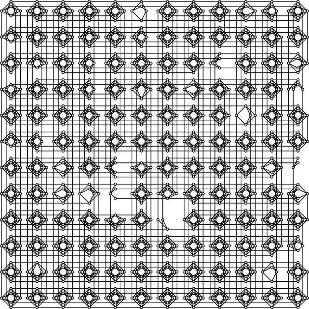
Edges represent the , and nodes represent the (and ). Physically, graph nodes are superconducting flux qubits, implemented as niobium rings that are written and read electromagnetically [Johnson et al. (2011)]. At superconducting temperatures—Ising operates at a mere 10.45 mK (0.01℃ above absolute zero)—quantum-mechanical effects (entanglement, superposition, and quantum tunneling) come into play. In Ising, 1095 (95.1%) of the qubits and 3061 (91.1%) of the couplers are operational.
Annealing times are also installation-dependent. Ising supports annealing times of 5–2000µs (user-selectable). Longer annealing times are theoretically more likely to find the input Hamiltonian’s global minimum, but shorter annealing times enable more attempts per unit time.
3 Related Work
Very little exists in terms of programming models and programming languages for gate-model quantum computers and quantum annealers.
Programming models for gate-model quantum computers
Although gate-model quantum computers are more heavily studied than quantum annealers, virtually all programming languages and compilers developed for these systems are based on the same underlying programming model: Place a specified gate at a specified location in a circuit, which is a directed acyclic graph. To illustrate this approach, Figure 2 presents an example of Grover’s search algorithm [Grover (1996)] in standard gate-model circuit notation.222The dashed box delineates the user-provided “oracle” function, which indicates if a set of inputs (2 bits, in this case) represents the item being searched for by flipping an ancilla qubit. Each gate (e.g., , , or CNOT []) represents a small unitary matrix that transforms the current state—in this case, a complex vector with 8 () elements.
\Qcircuit@C=1.25em @R=1.25em
\lstick\ket0 & \qw \gateH \gateX \ctrl2 \gateH \gateX \qw \ctrl1 \qw \gateX \gateH \meter \qw
\lstick\ket0 \qw \gateH \qw \ctrl1 \gateH \gateX \gateH \targ \gateH \gateX \gateH \meter \qw
\lstick\ket0 \gateX \gateH \qw \targ \qw \qw \qw \qw \qw \qw \qw \qw \qw\gategroup14350.5em–
The question is how to express algorithms such as the one shown in Figure 2 as computer code. OpenQASM [Cross et al. (2017)] is a domain-specific language in which the “statements” (x, h, cx, etc.) represent the application of a gate to one or more qubits, and programs can define parameterized macros to simplify repeated tasks. Scaffold [JavadiAbhari et al. (2015)] is similar but also supports C-style for loops to apply multiple gates in a fixed pattern. It further includes support for expressing classical oracles as gates. Quipper [Green et al. (2013)] and LIQ [Wecker and Svore (2014)] are embedded domain-specific languages, with the former embedded in Haskell and the latter embedded in F#, implying they have access to those languages’ code features. Like OpenQASM and Scaffold, Quipper and LIQ are based primarily on specifying an ordered sequence of gates applied to qubits, although in a functional-language context (e.g., a Quipper circuit runs within a Haskell monad). Quil [Smith et al. (2017)] and Q# [Microsoft Corp. (2017)] are recent domain-specific languages that, while sharing the same “ordered sequence of gates” abstraction as all the other efforts, put particular emphasis on tightly interleaving classical and quantum computation.
In short, the state of the art in programming models for gate-model quantum computers is at the level of an assembly language that offers various convenience features but little in the way of higher-level abstractions. The closest equivalent in the context of quantum annealing is perhaps QMASM [Pakin (2016)], which we introduce in Section 4.2 but then build upon to present a more expressive programming model based on classical circuits and, on top of that, one based on predicate logic. Unlike all of the works discussed above, in this paper we establish a large semantic gap between the programming model exposed by the underlying hardware and that presented to the user.
Quantum Prolog
[James et al. (2011)] (?) demonstrate that one can express the equivalent of a pure version of Prolog over finite relations in terms of a model of discrete quantum computing. (Conventionally, quantum computing is defined over Hilbert spaces, which are complex-valued.) This is one of the very few attempts to develop a high-level programming model for gate-model quantum computers, although for a form that has never been implemented. Besides targeting gate-model quantum computers rather than quantum annealers, this work differs from ours in that it focuses on the mathematical equivalency of relational programming and discrete quantum computing over the field of Booleans, while our work showcases the implementation of a Prolog compiler that generates code suitable for running on a physical quantum annealer.
Programming models for quantum annealers
Most of the literature that relates to programming quantum annealers focuses on expressing a single algorithm or single class of algorithms in terms of an Ising-model Hamiltonian (Equation 1). ?) surveys a number of such algorithms. More recent efforts include traveling-salesman problems [Heim et al. (2017)] and satisfiability problems [Hen and Young (2011)]. In contrast, our work is to make it possible to express problems without explicitly specifying individual and coefficients.
D-Wave Systems, Inc. provides a few tools that let one express problems in a higher-level form than a list of and coefficients. ToQ [D-Wave Systems, Inc. (2017b)], formerly Deqo [Dahl (2014)], is the most related tool to our quantum-annealing Prolog in that it is centered on constraint satisfaction and targets a quantum annealer. ToQ accepts a set of constraints and returns a set of values that satisfy those constraints. However, each individual constraint is evaluated classically and exhaustively; the D-Wave system is used only for combining individually satisfied constraints into a global problem and solving that. In contrast, our Prolog implementation performs all of its constraint satisfaction on the quantum annealer, not classically.
4 Implementation
4.1 Primitives
Tables 1 and 2 present the primitive mechanisms that one can use to represent a problem as an Ising-model Hamiltonian of the form stated in Equation 1.
| ✓ | |||
| ✓ | |||
| ✓ | ||||
| ✓ | ||||
| ✓ | ||||
| ✓ | ||||
Interpreting as false and as true, a negative expresses a preference for the corresponding being true (Table 1(a)) while a positive expresses a preference for the corresponding being false (Table 1(b)). The magnitude of the corresponds to the strength of the preference. A negative expresses a preference for the corresponding and having the same value (Table 2(a)) while a positive expresses a preference for the corresponding and having opposite values (Table 2(b)). In other words, can be interpreted as a wire in a digital circuit, and can be interpreted as an inverter. As with the , the magnitude of the corresponds to the strength of the preference.
One can set up a system of inequalities to find and values with a desired set (or sets) of in the ground state. This system of inequalities can be solved by hand in simple cases or with a constraint solver for more complicated cases. We use MiniZinc [Nethercote et al. (2007)] as our constraint-modeling language, but any similar system would suffice. Table 3(a) presents an Ising-model Hamiltonian, , whose 4-way degenerate ground state (meaning, the 4-way tie for the minimum value) is exactly the set of spins for which (i.e., logical conjunction).
| ✓ | ||||
| ✓ | ||||
| ✓ | ||||
| ✓ | ||||
| ✓ | ||||
| ✓ | ||||
| ✓ | ||||
| ✓ | ||||
The Hamiltonian was found by constraining the ground-state all to have the same value and all other to have a strictly greater value. Similarly, Table 3(b) presents an Ising-model Hamiltonian, , whose 4-way degenerate ground state is exactly the set of spins for which (i.e., logical disjunction).
It is worth noting that Hamiltonians are additive. Specifically, the ground state of is the intersection of the ground state of and the ground state of . The implication is that primitive operations like those shown in Table 3 can be trivially combined into more complicated expressions without having to solve a (computationally expensive) constraint problem for the overall expression. Because Ising-model Hamiltonians always have a non-empty ground state—they must have at least one minimum value—summing Hamiltonians whose ground states have an empty intersection can lead to an unintuitive ground state of the combined Hamiltonian. As a trivial example, has the unique ground state ; has the two-fold degenerate ground state and ; but has the three-fold degenerate ground state , , and .
In this work, however, we ensure by construction that we do not sum Hamiltonians whose intersection is empty. Specifically, because we sum Hamiltonians only for Boolean expressions and only by equating (cf. Table 2(a)) outputs to inputs and never outputs to outputs or inputs to inputs (i.e., we rely on a directed acyclic graph organization) we will not normally wind up with an empty intersection. The exception is in the case in which spins are “pinned” to values that introduce unsatisfiable output-output or input-input couplings, as discussed on Figure 4 in the following section.
Armed with Hamiltonians for and (Table 3(a)), or (Table 3(b)), and not (Table 2(b)) and the knowledge that Hamiltonians can be added together to produce new, more constrained Hamiltonians, we can implement a complete zeroth-order logic.
4.2 QA Prolog
We have implemented a Prolog compiler that compiles Prolog programs to a list of and coefficients for use with Equation 1. We call our implementation quantum-annealing Prolog or QA Prolog for short. Although the underlying concept is no more sophisticated than what was described in Section 4.1, a large software-engineering effort was needed to bridge the gap between what was presented there and a usable Prolog compiler.
Internally, QA Prolog comprises a number of software layers. The lowest layer is a “quantum macro assembler” we developed called QMASM [Pakin (2016)].333QMASM is freely available from https://github.com/lanl/qmasm. QMASM provides a thin but convenient layer of abstraction atop Equation 1. It lets programs refer to spins symbolically rather than numerically; shields the program from having to consider the specific underlying physical topology; and provides modularization through the use of macros that can be defined once and instantiated repeatedly.
As an example, Figure 3 shows how one can define and and or macros corresponding to the Hamiltonians portrayed by Table 3.
⬇ !begin_macro and A -0.5 B -0.5 Y 1.0 A B 0.5 A Y -1.0 B Y -1.0 !end_macro and
⬇ !begin_macro or A 0.5 B 0.5 Y -1.0 A B 0.5 A Y -1.0 B Y -1.0 !end_macro or
Lines containing a single symbol and a value correspond to an , and lines containing two symbols and a value correspond to a . Macros can be instantiated using the !use_macro directive.
The QMASM code in Figures 3(a) and 3(b) is compiled to a physical Hamiltonian, i.e., one that uses only the and that exist on the specific underlying hardware, with all coefficients scaled to the supported range. The D-Wave’s physical, Chimera-graph topology is not only fairly sparse but also contains no odd-length cycles—needed for the two A–B–Y cycles in Figure 3, for example—implying that a typical Hamiltonian must be embedded [Choi (2008)] into the physical topology. Doing so requires that additional spins and additional terms be added to the Hamiltonian and slightly alters the coefficients. For example, Figure 3(a) may compile to . A benefit of QMASM is that it lets programs work with arbitrary 2-local Ising Hamiltonians—support for higher-order interaction terms may be added in the future—while it automatically maps those Hamiltonians onto the available hardware.
Given that we can implement Boolean functions as Hamiltonians, we can take a large leap in abstraction and programmability and map Verilog programs [Thomas and Moorby (2002)] into the form of Equation 1. Verilog is a popular hardware-description language. Unlike QMASM, which looks foreign to a conventional-language programmer, the Verilog language supports variables, arithmetic operators, conditionals, loops, and other common programming-language constructs.
Verilog is a good match for current quantum annealers because, unlike most programming languages, it provides precise control over the number of bits used by each variable. With a total of only a few thousand bits (a few hundred bytes) available for both code and data combined on contemporary quantum annealers, there is no room for waste. Figure 4 presents an example of a Verilog module that inputs two 4-bit variables, this and that, and outputs a 5-bit variable, the_other, which is a function of the two inputs.
Although this program does not perform a useful function, it works
well for pedagogical purposes because it employs a variety of language
features including internal variables (defined with wire), a
relational operator (==), a C-style ternary conditional
(?:), multiplication, addition, and assignment.
We use Yosys [Wolf and Glaser (2013)], an open-source hardware-synthesis tool, to compile Verilog code to an EDIF (Electronic Design Interchange Format) netlist [Kahn et al. (2000)], a precise, machine-parseable description of a digital circuit. In addition to compiling, Yosys performs a number of optimizations on the design and, with the help of ABC [Brayton and Mishchenko (2010), Berkeley Logic Synthesis and Verification Group (2016)], transforms the design to use only a relatively small set of basic gates. A program we developed, edif2qmasm,444edif2qmasm is freely available from https://github.com/lanl/edif2qmasm. translates the EDIF netlist to a QMASM Hamiltonian. The generated code employs a standard-cell library of precomputed Hamiltonians for and, or, not, xor, and other such primitives.
In the case of Figure 4, the generated Hamiltonian comprises 263 and and 375 . We can “pin” values to the this and that inputs by specifying the as in Table 1, run the Hamiltonian on a quantum annealer, and read out the the_other output. (QMASM even supports pinning directly on the command line [Pakin (2016)].) We can alternatively pin the the_other output, run the Hamiltonian, and read out the two inputs; pin the output and one of the inputs and read out the other input; or pin nothing and read out valid mappings of inputs to outputs. (As could be expected, though, if the function were non-surjective, specifying an output that is not the image of any element in the function’s domain will not result in valid inputs.) In essence, we support a relational semantics in a language that does not normally offer such a capability.
The final piece of QA Prolog is the Prolog compiler itself. QA Prolog supports only a subset of Prolog but enough to handle basic constraint logic programming. For instance, QA Prolog supports atoms and positive integers but not floating-point numbers, strings, lists, first-class compound terms, or any other data type. It supports arithmetic and relational operations but not ! (cut), fail, or any impure predicates. Clauses can reference other clauses but not recursively. Polymorphic clauses are not supported, but integer/1 and atom/1 can be used to disambiguate otherwise polymorphic clauses. QA Prolog does support unification [Robinson (1965)], backtracking, and predicates comprising multiple clauses.
Importantly, QA Prolog allows the goals in a rule’s body to be specified in any order without impacting their ability to be proven. In particular, operations can be performed on variables even before they are ground. This is in contrast to basic Prolog—as opposed to Prolog with the library(clpfd) predicates [Triska (2012)]—which is limited in its ability to manipulate free variables.
After the usual lexing and parsing steps, the compiler performs type inference on the abstract syntax tree. Because so few spins are available in current hardware, distinguishing between the two supported data types lets the compiler represent each of them using a different numbers of bits: bits for atoms, assuming distinct atoms are named in the program, and bits for integers, assuming the largest integer appearing literally in the program is . A QA Prolog command-line argument lets the user increase the number of bits per integer in case larger values are needed for intermediate results.
Once all types are inferred, QA Prolog’s code generator generates Verilog code. Although compiling Prolog to Verilog appears, on the surface, to be a peculiar strategy, recall that
-
1.
our quantum-annealing implementation of Verilog already has a relational semantics,
-
2.
Verilog provides arithmetic and relational operations, saving QA Prolog from having to implement those itself,
-
3.
hardware-synthesis tools such as Yosys perform a number of logic optimizations and simplifications on QA Prolog’s behalf, and
-
4.
QA Prolog gets unification support “for free” because the same spins are used to represent every instance of the same variable appearing in the Verilog code.
In the compilation from Prolog to Verilog, each predicate (including all clauses) is converted to a single Verilog module. Because the names of Verilog arguments must be unique, arguments are renamed. In Prolog terms, this is like replacing the fact “same(X, X).” with the rule “same(A, B) :- A = B.”. In addition, an extra, single-bit argument called Valid is included in the argument list. This is an output value that is set to 1 if and only if all goals are proved. Queries that include variables are implemented by pinning Valid to 1 and letting the annealing process solve for all the variables so as not to violate that condition. Queries that do not include variables leave Valid unpinned and let the annealing process find a value for it that does not violate any other conditions.
Once QA Prolog has compiled the Prolog source code—including the query, which can be specified on the command line—to Verilog, QA Prolog invokes Yosys, edif2qmasm, and QMASM, as illustrated in Figure 5.
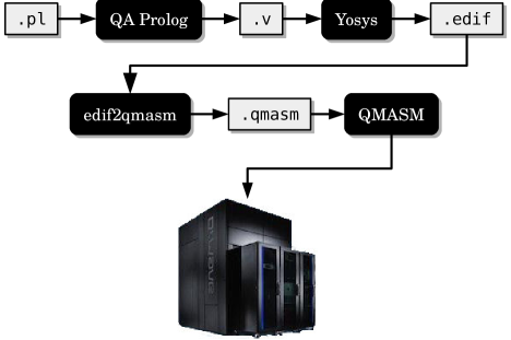
With the help of D-Wave’s SAPI library [D-Wave Systems, Inc. (2017a)], QMASM remotely executes the user’s program on a D-Wave system and reports the (Boolean) value of each symbol appearing in the QMASM source file. QA Prolog maps these lists of Booleans back to integers and named atoms, associates those values with variables named in the user’s query, and reports all variables and their values to the user just like a typical Prolog environment would.
A quantum annealer always returns a vector of spins (); there is no notion of “no result found”. Although QMASM can detect certain obviously incorrect results and discard them, in the general case, QA Prolog can return incorrect results. Consider the constraint logic program, “impossible(X) :- X < 4, X > 4.”. Although impossible(X) should never succeed, QA Prolog proposes all eight 3-bit integers as possible solutions, as all eight are equally bad choices. We do not consider this odd behavior a showstopper because many important problems in P and NP have solutions that can be (classically) verified quickly. A user can run QA Prolog to quickly produce a set of candidate solutions then filter out invalid ones as part of a post-processing step.
5 Evaluation
In this section, we examine what QA Prolog is and is not capable of expressing. A expands upon this section by presenting all of the transformations a particular program undergoes from Prolog source code to a 2-local Ising Hamiltonian. Our main metric in this section is the cost in spins for various programs. Figure 6 presents a Prolog program that defines an and/3 predicate in terms of an and/2 predicate, which itself is defined by four facts.
Note that this example does not involve any constraint logic programming.
Compiling Figure 6 with QA Prolog results in a logical Hamiltonian with 26 spins, and QMASM assembles that into a physical Hamiltonian with 42 spins. For comparison, a hand-constructed logical Hamiltonian for a 3-input and requires only 5 spins,555, where is an ancilla spin needed to produce the correct ground state. and QMASM assembles that into a physical Hamiltonian containing 10 spins.
Next, consider a Prolog program that finds two positive integers whose sum and product are each 4 (Figure 7).
When run with the query “fours(A, B)”, the program correctly produces “A = 2, B = 2”. The program in fact additionally produces “A = 6, B = 6”. Because 3 is the minimum number of bits needed to represent all integers appearing literally in Figure 7, QA Prolog represents all numbers with that many bits. Because and , the second solution is valid, albeit a bit surprising.
Even a program this small consumes a large number of spins, primarily because of the 3-bit multiplication. Specifically, it maps to 24 logical spins at the QMASM level, which in turn get mapped to 39 physical spins or 3.6% of the total available on LANL’s D-Wave 2X system. The number of logical spins is a function of both the compilation tools (Yosys and ABC, in this case) and the set of precomputed Hamiltonians included in edif2qmasm’s standard-cell library. The number of physical spins is a function of the both the physical topology and the minor-embedding algorithm—and the random-number generator’s state in the case of a stochastic embedder such as the one we use [Cai et al. (2014)].
The total end-to-end execution time, including all of the compilation steps and the network connection to the D-Wave 2X, averages s over 100 trials. For each trial, we specified an annealing time of 20 µs and had the hardware perform 1000 anneals, enabling a maximum of 1000 unique solutions to be returned. Hence, a fixed 20 ms of the end-to-end time is the computation proper—the actual annealing time. Although the end-to-end time is high, our belief is that this time will grow slower with program complexity than would a classical implementation. Remember: all goals in the entire program are effectively evaluated in parallel. Not only are CLP semantics honored, but there is no additional performance cost for going beyond plain Prolog’s unification capabilities.
What are the limits on the Prolog programs that can be run on a D-Wave 2X using QA Prolog? We found that the “light meal” example from Dutra’s CLP tutorial [Dutra (2010)] is too large to fit, but if we skip dessert, as in Figure 8, the code runs, with 170 logical spins dilating to 602 physical spins.
As a more controlled experiment, consider a mult/3 predicate defined as “mult(A, B, C) :- C = A*B.”. Because of QA Prolog’s support for CLP, we can provide a value only for C in a query to factor C into A and B. The reader should note that this one-line integer-factoring program for a quantum annealer is conceptually far simpler than Shor’s famous integer-factoring algorithm for gate-model quantum computers [Shor (1999)], which requires knowledge of both quantum mechanics and number theory to understand. By factoring a relatively small number, say 6, we can steadily increase the bit width and measure the number of logical and physical spins required to represent the program.
Figure 9 presents the results of this study.
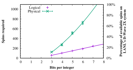
The number of logical spins for a given bit width does not change from compilation to compilation, but the number of physical spins does because it relies on a stochastic minor-embedding algorithm [Cai et al. (2014)]. Consequently, the figure includes error bars for physical spin counts. Points represent measurements; lines represent regressions. The regression curves used are and . Both have a coefficient of determination . As Figure 9 indicates, the number of physical spins grows faster than the number of logical spins. For integer factorization, we run out of physical spins at 7 bits per integer.
6 Conclusions
Quantum annealers represent a radical departure from conventional computer architectures. Rather than perform a sequence of operations that modify state (registers and memory), a quantum annealer performs in hardware a particular type of NP-hard optimization problem. Specifically, it finds a set of Boolean values (spins) that minimize a real-valued, fixed-form function of a potentially large number of variables. In effect, a quantum annealer evaluates the function in parallel for all possible inputs and reports in a fixed length of time (microseconds) the best instance found. The catch is that the solution is not guaranteed to be optimal.
Although quantum annealers offer the potential for huge performance gains through massive effective parallelism, programming them can be a challenge. At the lowest level, a program for a quantum annealer is merely a list of coefficients for the aforementioned fixed-form pseudo-Boolean function. The question we sought to answer in this work is, Can one express constraint logic programming in the form accepted by quantum-annealing hardware? The key insight we make in answering that question is identifying an analogy between expression minimization in an Ising-model Hamiltonian and unification in constraint logic programming.
Based on that insight we implemented QA Prolog, a compiler that, through a sequence of transformations, converts Prolog programs into 2-local Ising-model Hamiltonians, runs these on a D-Wave quantum annealer, and reports the results in terms of program variables. We draw the following conclusions from our study:
-
1.
Despite the enormous semantic gap, it is indeed possible to automatically convert constraint logic programs, expressed in a subset of Prolog, to the solution to an optimization problem, expressed as coefficients to a 2-local Ising-model Hamiltonian.
-
2.
An important limiting factor is the number of spins needed to express even trivial constraint logic problems. Our experimental platform, a D-Wave 2X quantum annealer installed at Los Alamos National Laboratory, has 1095 spins. One can think of those 1095 spins as corresponding to roughly 136 bytes of memory, which need to hold all program inputs, outputs, and logic.
-
3.
End-to-end performance (i.e., including compilation time) is poor: a few seconds for even trivial CLP problems. Although we expect these times to rise slowly with problem size and complexity we cannot confirm that hypothesis or compare it to classical implementations until we can execute programs sufficiently large so as to challenge classical CLP systems.
Even considering the preceding shortcomings we remain optimistic about the potential of exploiting the massive effective parallelism provided by quantum annealers to accelerate the execution of constraint logic programs. Although the hardware is in its early generations, when increased scale and other engineering improvements are put into place, QA Prolog will be ready to take advantage of these advances.
References
- Barahona (1982) Barahona, F. 1982. On the computational complexity of Ising spin glass models. Journal of Physics A: Mathematical and General 15, 10, 3241.
- Berkeley Logic Synthesis and Verification Group (2016) Berkeley Logic Synthesis and Verification Group. 2016. ABC: A system for sequential synthesis and verification. Available from http://www.eecs.berkeley.edu/~alanmi/abc/.
- Bravyi et al. (2006) Bravyi, S., Bessen, A. J., and Terhal, B. M. 2006. Merlin-Arthur games and stoquastic complexity. arXiv:quant-ph/0611021v2.
- Bravyi and Hastings (2017) Bravyi, S. and Hastings, M. 2017. On complexity of the quantum Ising model. Communications in Mathematical Physics 349, 1 (Jan.), 1–45.
- Brayton and Mishchenko (2010) Brayton, R. and Mishchenko, A. 2010. ABC: An academic industrial-strength verification tool. In Proceedings of the 22nd International Conference on Computer Aided Verification, T. Touili, B. Cook, and P. Jackson, Eds. Springer Berlin Heidelberg, Edinburgh, United Kingdom, 24–40.
- Bunyk et al. (2014) Bunyk, P. I., Hoskinson, E. M., Johnson, M. W., Tolkacheva, E., Altomare, F., Berkley, A. J., Harris, R., Hilton, J. P., Lanting, T., Przybysz, A. J., and Whittaker, J. 2014. Architectural considerations in the design of a superconducting quantum annealing processor. IEEE Transactions on Applied Superconductivity 24, 4 (Aug.), 1–10.
- Cai et al. (2014) Cai, J., Macready, B., and Roy, A. 2014. A practical heuristic for finding graph minors. arXiv:1406.2741 [quant-ph].
- Choi (2008) Choi, V. 2008. Minor-embedding in adiabatic quantum computation: I. the parameter setting problem. Quantum Information Processing 7, 5 (Oct.), 193–209.
- Cormen et al. (2001) Cormen, T. H., Leiserson, C. E., Rivest, R. L., and Stein, C. 2001. Introduction to Algorithms, 2nd ed. MIT Press.
- Cross et al. (2017) Cross, A. W., Bishop, L. S., Smolin, J. A., and Gambetta, J. M. 2017. Open quantum assembly language. arXiv:1707.03429 [quant-ph].
- D-Wave Systems, Inc. (2017a) D-Wave Systems, Inc. 2017a. Developer Guide for Python. D-Wave Systems, Inc., Burnaby, British Columbia, Canada.
- D-Wave Systems, Inc. (2017b) D-Wave Systems, Inc. 2017b. ToQ Overview. D-Wave Systems, Inc., Burnaby, British Columbia, Canada. ToQ documentation, qOp version 2.3.1.
- Dahl (2014) Dahl, E. D. 2014. Deqo: A Direct Embedding Quantum Optimizer. D-Wave Systems, Inc.
- Dutra (2010) Dutra, I. 2010. Constraint logic programming: A short tutorial. Available from https://www.dcc.fc.up.pt/~ines/talks/clp-v1.pdf.
- Farhi and Gutmann (1998) Farhi, E. and Gutmann, S. 1998. Analog analogue of a digital quantum computation. Physical Review A 57, 2403–2406.
- Feynman (1986) Feynman, R. P. 1986. Quantum mechanical computers. Foundations of Physics 16, 6 (June), 507–531.
- Finnila et al. (1994) Finnila, A. B., Gomez, M. A., Sebenik, C., Stenson, C., and Doll, J. D. 1994. Quantum annealing: A new method for minimizing multidimensional functions. Chemical Physics Letters 219, 5, 343–348.
- Fujitsu Ltd. (2017) Fujitsu Ltd. 2017. Quantum computing and AI start a new era. Fujitsu Journal.
- Gansner and North (2000) Gansner, E. R. and North, S. C. 2000. An open graph visualization system and its applications to software engineering. Software—Practice and Experience 30, 11 (Sept.), 1203–1233.
- Green et al. (2013) Green, A. S., Lumsdaine, P. L., Ross, N. J., Selinger, P., and Valiron, B. 2013. Quipper: A scalable quantum programming language. In Proceedings of the 34th ACM SIGPLAN Conference on Programming Language Design and Implementation. ACM, New York, New York, USA, 333–342.
- Grover (1996) Grover, L. K. 1996. A fast quantum mechanical algorithm for database search. In Proceedings of the Twenty-eighth Annual ACM Symposium on Theory of Computing. ACM, New York, NY, USA, 212–219.
- Heim et al. (2017) Heim, B., Brown, E. W., Wecker, D., and Troyer, M. 2017. Designing adiabatic quantum optimization: A case study for the traveling salesman problem. arXiv:1702.06248v1 [quant-ph].
- Hen and Young (2011) Hen, I. and Young, A. P. 2011. Exponential complexity of the quantum adiabatic algorithm for certain satisfiability problems. Physical Review E 84, 061152.
- James et al. (2011) James, R. P., Ortiz, G., and Sabry, A. 2011. Quantum computing over finite fields. arXiv:1101.3764 [quant-ph].
- JavadiAbhari et al. (2015) JavadiAbhari, A., Patil, S., Kudrow, D., Heckey, J., Lvov, A., Chong, F. T., and Martonosi, M. 2015. ScaffCC: Scalable compilation and analysis of quantum programs. Parallel Computing 45, 2–17.
- Johnson et al. (2011) Johnson, M. W., Amin, M. H. S., Gildert, S., Lanting, T., Hamze, F., Dickson, N., Harris, R., Berkley, A. J., Johansson, J., Bunyk, P., Chapple, E. M., Enderud, C., Hilton, J. P., Karimi, K., Ladizinsky, E., Ladizinsky, N., Oh, T., Perminov, I., Rich, C., Thom, M. C., Tolkacheva, E., Truncik, C. J. S., Uchaikin, S., Wang, J., Wilson, B., and Rose, G. 2011. Quantum annealing with manufactured spins. Nature 473, 7346 (May), 194–198.
- Kadowaki and Nishimori (1998) Kadowaki, T. and Nishimori, H. 1998. Quantum annealing in the transverse Ising model. Physical Review E 58, 5355–5363.
- Kahn et al. (2000) Kahn, H., La Fontaine, R., and Lau, R. 2000. Electronic design interchange format (EDIF): Part 2: Version 4 0 0. Standard IEC 61690-2:2000, International Electrotechnical Commission, Manchester, United Kingdom. Jan.
- Kaminsky et al. (2004) Kaminsky, W. M., Lloyd, S., and Orlando, T. P. 2004. Scalable superconducting architecture for adiabatic quantum computation. arXiv:quant-ph/0403090v2.
- Kirkpatrick et al. (1983) Kirkpatrick, S., Gelatt, C. D., and Vecchi, M. P. 1983. Optimization by simulated annealing. Science 220, 4598 (May), 671–680.
- Knight (2017) Knight, W. 2017. IBM raises the bar with a 50-qubit quantum computer. MIT Technology Review.
- Lucas (2014) Lucas, A. 2014. Ising formulations of many NP problems. Frontiers in Physics 2, 5.
- Microsoft Corp. (2017) Microsoft Corp. 2017. The Q# progamming language. Available from https://docs.microsoft.com/en-us/quantum/quantum-qr-intro.
- Nethercote et al. (2007) Nethercote, N., Stuckey, P. J., Becket, R., Brand, S., Duck, G. J., and Tack, G. 2007. MiniZinc: Towards a standard CP modelling language. In Proceedings of the 13th International Conference on Principles and Practice of Constraint Programming, C. Bessière, Ed. Springer, Berlin, Heidelberg, 529–543.
- Pakin (2016) Pakin, S. 2016. A quantum macro assembler. In Proceedings of the 2016 IEEE High Performance Extreme Computing Conference (HPEC).
- Robinson (1965) Robinson, J. A. 1965. A machine-oriented logic based on the resolution principle. Journal of the ACM 12, 1 (Jan.), 23–41.
- Shor (1999) Shor, P. W. 1999. Polynomial-time algorithms for prime factorization and discrete logarithms on a quantum computer. SIAM Review 41, 2, 303–332.
- Smith et al. (2017) Smith, R. S., Curtis, M. J., and Zeng, W. J. 2017. A practical quantum instruction set architecture. arXiv:1608.03355 [quant-ph].
- Thomas and Moorby (2002) Thomas, D. and Moorby, P. 2002. The Verilog Hardware Description Language, 5th ed. Springer.
- Triska (2012) Triska, M. 2012. The finite domain constraint solver of SWI-Prolog. In Proceedings of the Eleventh International Symposium on Functional and Logic Programming (FLOPS 2012). Number 7294 in Lecture Notes in Computer Science. Kobe, Japan, 307–316.
- Wecker and Svore (2014) Wecker, D. and Svore, K. M. 2014. LIQ: A software design architecture and domain-specific language for quantum computing. arXiv:1402.4467 [quant-ph].
- Wielemaker et al. (2012) Wielemaker, J., Schrijvers, T., Triska, M., and Lager, T. 2012. SWI-Prolog. Theory and Practice of Logic Programming 12, 1–2 (Jan.), 67–96.
- Wolf and Glaser (2013) Wolf, C. and Glaser, J. 2013. Yosys—a free Verilog synthesis suite. In Proceedings of the 21st Austrian Workshop on Microelectronics (Austrochip 2013). Linz, Austria.
- Yamaoka et al. (2016) Yamaoka, M., Yoshimura, C., Hayashi, M., Okuyama, T., Aoki, H., and Mizuno, H. 2016. A 20k-spin Ising chip to solve combinatorial optimization problems with CMOS annealing. IEEE Journal of Solid-State Circuits 51, 1 (Jan.), 303–309.
Appendix A An end-to-end example
In this section we detail the complete QA Prolog compilation and execution process illustrated in Figure 5. Figure 10 presents a Prolog source file that defines a bigger/2 predicate, which we query with “bigger(Big, Little)”. Because the constraint logic works on free variables, this example does not work with ordinary Prolog environments. For instance, SWI-Prolog [Wielemaker et al. (2012)] returns an “Arguments are not sufficiently instantiated” error.
QA Prolog compiles bigger/2 and the associated query into the Verilog code shown in Figure 11. Because the largest integer literal appearing in the Prolog source code is 15, the Verilog code uses 4-bit integers throughout.
The EDIF netlist that Yosys produces from Figure 11 is a rather verbose s-expression. Rather than present it here, Figure 12 shows a visualization of the circuit that that Yosys renders using Graphviz [Gansner and North (2000)]. The notation that Yosys uses indicates how bits are renumbered as they flow from one component to the next. “OAI3” represents a 3-input or-and-invert gate: .

edif2qmasm translates the circuit illustrated in Figure 12 to the QMASM code listed in Figure 13. In QMASM syntax, “=” specifies a chain (a strongly negative ) and “<->” specifies an alias (multiple names for the same spin). The translation from EDIF constructs to QMASM constructs is nearly one-to-one, which makes the process fairly straightforward.
Finally, QMASM assigns each variable to one or more physical spins that are available on the target hardware. Because the process contains some stochastic elements, Figure 14 presents only one instance of a mapping to the hardware. In the case shown, the Hamiltonian uses 76 and 101 .
The Big variable in the Prolog query is mapped to the bit string , and the Little variable in the query is mapped to the bit string (both big-endian). The Valid bit (Figure 11) is mapped to .
We ran the Figure 14 Hamiltonian on LANL’s D-Wave 2X system, specifying that we wanted 1000 samples of the vector and an annealing time of 20µs. The D-Wave 2X found exactly the three valid solutions: “Big = 8, Little = 7” (139 instances), “Big = 9, Little = 7” (137 instances), and “Big = 9, Little = 8” (226 instances). QMASM automatically rejected the remaining instances. (It is not uncommon for a quantum annealer to return an invalid solution, which is analogous to a classical optimization algorithm getting stuck in a local minimum.) Although only 20 ms were spent performing quantum annealing, a total of 200 ms of real time was spent on the D-Wave 2X. This includes various requisite pre- and post-processing tasks.
The total end-to-end time, including not only the time spent on the D-Wave 2X but also the time spent in QA Prolog, Yosys, edif2qmasm, QMASM, the local filesystem, and various networks between the development workstation and the D-Wave 2X, averages s over 100 trials. Clearly, a problem like the one used in this exercise is insufficiently complex to overcome the numerous overheads and observe an increase in performance over what can readily be achieved classically.