Advanced IEEE 802.11ax TCP aware scheduling under unreliable channels
Abstract
In this paper we suggest advanced IEEE 802.11ax TCP-aware scheduling strategies for optimizing the AP operation under transmission of unidirectional TCP traffic. Our scheduling strategies optimize the performance using the capability for Multi User transmissions over the Uplink, first introduced in IEEE 802.11ax, together with Multi User transmissions over the Downlink. They are based on Transmission Opportunities (TXOP) and we suggest three scheduling strategies determining the TXOP formation parameters. In one of the strategies one can control the achieved Goodput vs. the delay. We also assume saturated WiFi transmission queues. We show that with minimal Goodput degradation one can avoid considerable delays.
Keywords: IEEE 802.11ax; TCP; Aggregation; Transmission Opportunity; Goodput; Multi User; MIMO; OFDMA;
1 Introduction
1.1 Background
In 2013 the IEEE established a new Task Group (TG), denoted TGax, in order to establish a new standard for the IEEE 802.11 networks [1]. The functional requirements for IEEE 802.11ax, also denoted High Efficiency WLAN (HEW) [2] are to achieve at least four times as much improvement in the average throughput per station compared to former versions of the IEEE 802.11 standards [3], and to support dense deployment environments [4, 5, 6, 7, 8].
In order to achieve these goals, several new features are considered by TGax including physical layer techniques, medium access control layer strategies, spatial frequency reuse schemes and power saving mechanisms.
In the physical layer the new techniques are adopting Orthogonal Frequency Division Multiple Access (OFDMA) and deploying Multi User Multiplex-Input Multiplex-Output (MU-MIMO) over the DL and UL.
Concerning the MAC layer, in order to improve the Basic Service Set (BSS) throughput, it is crucial to develop an efficient MAC scheme which can reduce the probability of a transmission collision among different stations, allow for simultaneous transmissions in the same BSS and decrease the channel time for transmission of control information. One way to achieve the above goals is to improve the basic access mechanism in IEEE 802.11 networks, namely Distributed Coordination Function (DCF) based on Carrier Sense Multiple Access with Collision Avoidance (CSMA/CA). The second way is to focus on new MAC schemes for simultaneous multi user transmissions, based on the OFDMA and MIMO technologies.
1.2 Research question
One of the remarkable additions in IEEE 802.11ax is to enable MU-MIMO and/or OFDMA over the Uplink, with combination of MU-MIMO and/or OFDMA over the Downlink, where only DL MU-MIMO was possible in the predecessor of IEEE 802.11ax, namely IEEE 802.11ac [3]. MU over the UL enables simultaneous transmissions of several stations to the AP. In this paper we evaluate several scheduling strategies in order to optimize the performance of MU over the Downlink and Uplink in relation to TCP traffic which is composed of two way traffic; one way for the TCP Data segments and the other way for the TCP Ack segments.
The current paper is a continuation of papers [11, 9, 10, 12, 13]. In papers [11, 9, 10, 12] the authors suggest scheduling strategies for the parallel transmissions of the AP to a given set of stations using new features of IEEE 802.11ax . The authors assume UDP-like traffic where the AP transmits data MAC Service Data Units (MSDUs) to the stations, which reply with MAC acknowledgments. In paper [13] and in this paper we assume a DL unidirectional TCP-like traffic in which the AP transmits TCP Data MSDUs to a given set of stations, and the stations reply with TCP Ack MSDUs. The differences between this paper and paper [13] is that in paper [13] the assumption is that the channel is reliable, while in this paper we extend the work to unreliable channels, which opens the door for the use of advanced transmission strategies and considers the impact of various channels as reflected by the use of different MCSs over the DL and UL. As far as we know the issue of transmitting TCP traffic over IEEE 802.11ax has not yet been investigated, except in paper [13]. We suggest several TCP-aware scheduling strategies for transmission of unidirectional TCP Data segments over the DL and TCP Ack segments over the UL using Multi User (MU) mode for 4, 8, 16 and 32 stations scenarios over an unreliable channel. This is one of the aspects to compare between new amendments of the IEEE 802.11 standard [14]. In this paper we are interested in finding a theoretical upper bound on the maximum DL unidirectional TCP Goodput that can be achieved by IEEE 802.11ax without any delay restriction and comparing between the various TCP-aware scheduling strategies. Therefore, due to a very short round trip delay we assume the traffic saturation model where TCP connections always have data to transmit ( no limit on the amount of TCP Data segments waiting and on the TCP transmission queue ) and the TCP Ack is generated immediately by receivers. Second, we neutralize any aspects of the PHY layer as the number of Spatial Streams (SS) in use and channel correlation when using MU, the use in the sounding protocol etc. We also use equal Resource Units (RUs) allocation for all served stations and optimize the MU-MIMO/OFDMA in order to reduce the overhead and to increase the Goodput.
As mentioned, we assume that every TCP connection has enough TCP Data segments to fulfill the next PPDU and we assume that transmissions are made using an optimized ( in terms of overhead reduction and Goodput maximization ) two level aggregation scheme to be described later. Our goal is to find an upper bound on the maximum possible Goodput that the wireless channel enables the TCP connections, where the TCP itself does not impose any limitations on the offered load, i.e. on the rate that MSDUs are given for transmission to the MAC layer of the IEEE 802.11ax. We then optimize the delay within minimal Goodput maximization. We also assume that the AP and the stations are the end points of the TCP connections. Following e.g. [15, 16, 17, 18] it is quite common to consider short Round Trip Times (RTT) in this kind of high speed network such that no retransmission timeouts occur. Moreover, we assume that every TCP connections’ Transmission Window can always provide as many MSDUs to transmit as the IEEE 802.11ax protocol limits enable. This assumption follows the observation that aggregation is useful in a scenario where the offered load on the channel is high.
This research is an additional step in investigating TCP traffic in IEEE 802.11ax. In our further papers we plan to address other TCP traffic scenarios to investigate such as UL unidirectional TCP traffic and bi-directional TCP traffic and to reflect other protocol limitations.
1.3 Previous works
Most of the research papers on IEEE 802.11ax thus far examine new mechanisms in the PHY and MAC layers of the IEEE 802.11ax proposal [19, 20, 21, 22, 23, 24, 25, 26, 27, 28, 29, 30, 31, 32, 33]. The issue of TCP traffic over IEEE 802.11ac networks has been investigated, e.g. in [34, 35, 36], for uni-directional DL TCP traffic, uni-directional UL TCP traffic and both bi-directional DL and UL TCP traffic. However, in all these works there is no possibility of using the MU operation mode over the UL, a feature that was first introduced in IEEE 802.11ax . To the best of our knowledge, paper [13] is the first and only paper so far that deals with TCP traffic over IEEE 802.11ax networks. In this paper the authors assume a reliable channel and saturated TCP traffic and show two-level aggregation efficient packing policy of TCP Data/Ack segments in MAC Protocol Data Units (MPDUs). They suggest three scheduling strategies for the transmission of DL TCP Data segments based on Single User (SU) and OFDMA+MU-MIMO PHY layers, and consider 4, 8, 16, 32 and 64 stations in the system and measure the TCP Goodput of the system using TXOPs as will be described later in this paper. The main findings are that for 4 and 8 stations the MU strategies outperform the SU one, for 16 and 32 stations the MU and SU strategies have about the same performance and in the case of 64 stations the SU strategy outperforms the MU ones.
In this paper we extend previous works by assuming an unreliable channel and so the efficient packing used in [13] cannot be used. Therefore, we suggest another TCP-aware scheduling strategy; consider the use of different Modulation/Coding schemes (MCSs) over the DL/UL which together with the bandwidth and the Signal-to-Noise Ratio (SNR) influence the Bit Error Rate (BER).
The remainder of the paper is organized as follows: In Section 2 we describe the new mechanisms of IEEE 802.11ax relevant to this paper. In Section 3 we describe the operation mode and the TCP-aware scheduling strategies suggested. We assume the reader is familiar with the basics of PHY and MAC layers of IEEE 802.11 described in previous papers, e.g. [37]. In Section 4 we present the simulation results for the Goodput and Delay of the various proposed TCP-aware scheduling strategies and Section 5 summarizes the paper. In the Appendix we show an example of the relation between the channel bandwidth, Modulation/Coding schemes in use and the Signal-to-Noise-Ratio to the received Bit Error Rate. Lastly, moving forward, we denote IEEE 802.11ax by 11ax .
2 New features in IEEE 802.11ax
As mentioned, 11ax focuses on implementing mechanisms to efficiently serve more users, enabling consistent and reliable streams of data ( average throughput per user ) in the presence of multiple users. In order to meet these targets we mention a few new 11ax mechanisms in both the PHY and MAC layers, relevant to this paper. At the PHY layer, 11ax enables larger OFDM FFT sizes (4X larger) and therefore every OFDM symbol is compared to in IEEE 802.11ac, the predecessor of 11ax . By narrower sub-carrier spacing (4X closer) the protocol efficiency is increased because the same Guard Interval (GI) is used both in 11ax and in previous versions of the standard.
In addition, to increase the average throughput per user in high-density scenarios, 11ax introduces two new Modulation Coding Schemes (MCSs), MCS10 (1024 QAM ) and MCS 11 (1024 QAM 5/6), applicable for transmission with bandwidth larger than 20 MHz.
In this paper we use the Transmission Opportunity (TXOP) feature first introduced in IEEE 802.11n [38]. This feature allows a station, after gaining access to the channel, to transmit several PHY Protocol Data Units (PPDUs) in a row without interruption. For scenarios with bidirectional traffic such as TCP Data/Ack segments, this approach is very efficient as it reduces contention in the wireless channel and reduces delay by sending the TCP Acks in the same TXOP.
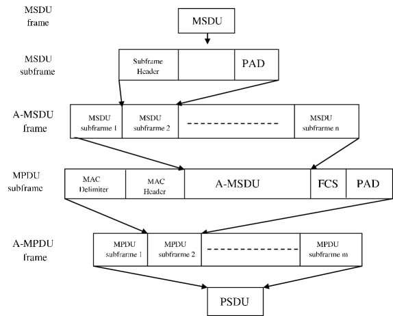
We focus on optimizing the TXOP duration and pattern, PPDU duration and the 11ax’s two-level aggregation scheme working point first introduced in IEEE 802.11n [38], in which several MPDUs can be aggregated to be transmitted in a single PHY Service Data Unit (PSDU). Such aggregated PSDU is denoted Aggregate MAC Protocol Data Unit (A-MPDU) frame. In two-level aggregation every MPDU can contain several MSDUs. MPDUs are separated by an MPDU Delimiter field of 4 bytes and each MPDU contains MAC Header and Frame Control Sequence (FCS) fields. MSDUs within an MPDU are separated by a SubHeader field of 14 bytes. Every MSDU is rounded to an integral multiple of 4 bytes together with the SubHeader field. Every MPDU is also rounded to an integral multiple of 4 bytes.
In 11ax the size of an MPDU is limited to 11454 bytes and the size of the A-MPDU frame is limited to 4,194,304 bytes. The transmission time of the PPDU (PSDU and its preamble) is limited to () due to the L-SIG (one of the legacy preamble’s fields) duration limit [1]. The A-MPDU frame structure in two-level aggregation is shown in Figure 1.
IEEE 802.11ax also enables extension of the MAC acknowledgment mechanism by using an acknowledgment window of 256 MPDUs. In this paper we also assume that all MPDUs transmitted in an A-MPDU frame are from the same Traffic Stream (TS). In this case up to 256 MPDUs are allowed in an A-MPDU frame of 11ax.
Recall that in 11ax it is also possible to use MU-MIMO over the UL. It is possible to transmit/receive simultaneously to/from up to 74 stations over the DL/UL respectively.
Finally, in this paper we assume an unreliable channel and therefore the use of the IEEE 802.11 Automatic-ReQuest response (ARQ) protocol. We do not specify this protocol here. The interested reader can find a description of this protocol in e.g. paper [39].
3 Model
3.1 IEEE 802.11ax (HE) TCP aware scheduling strategies
3.1.1 IEEE 802.11ax (HE) DL unreliable channel, simultaneous Multi User unidirectional TCP operation mode
In the HE DL unreliable channel, simultaneous MU unidirectional TCP, the AP transmits TCP Data segments to several stations simultaneously and receives TCP Ack segments from the stations simultaneously. We assume the following 11ax operation mode where simultaneous DL TCP Data segments are sent by the AP to multiple stations in the same PPDU using MU mode, and the TCP Ack segments are sent simultaneously by the stations in one PPDU by again using MU mode under unreliable channel conditions as is illustrated in Figure 2.
In the proposed operation mode, after waiting the BackOff and AIFS intervals, the AP receives an air access and starts a TXOP by transmitting a DL HE MU PPDU frame containing A-MPDU frames which contain TCP Data segments, to a given set of stations simultaneously using MU mode. In the DL PPDU the AP transmits one A-MPDU frame to every station in the MU stations’ set, i.e. group of stations. Every A-MPDU contains several MPDU frames and each MPDU contains several MSDUs, which are TCP Data segments. The MPDU frames in an A-MPDU are acknowledged by a BAck frame from their receiver and all the BAck frames are also transmitted simultaneously by the stations using HE UL MU mode. After the AP receives the BAck frames the so-called HE DL MU TCP Data cycle ends and such a Data cycle can now repeat itself several times.
In order to reduce the delay one needs to transmit to or receive from a group of stations simultaneously, and therefore the AP needs to allocate Resource Units (RU) per served station. A RU is a subchannel and RU allocation is done for the DL for TCP Data segments and for the UL for the BAck frames and the TCP Ack segments’ transmissions based on the traffic profile and channel conditions. According to the 11ax protocol, the AP signals the stations when and how to transmit, i.e. their UL RU allocation, by a Trigger Frame (TF) control frame. For the BAck transmissions the AP transmits a unicast Trigger Frame (TF) to every station that contains the UL RU allocation. This TF MPDU is aggregated with the DL Data MPDUs that the AP transmits to a station in the DL HE MU A-MPDU frame.
At the end of the last HE DL MU TCP Data cycle the AP initiates a HE UL MU TCP Ack cycle by transmitting the broadcast Trigger Frame (TF) to the MU stations’ set, i.e. group of stations. This TF solicits MU UL Data transmissions that contain TCP Ack transmissions from the stations to the AP via the same unreliable channel. In this UL transmission the stations transmit TCP Ack segments using UL HE MU A-MPDU frames using HE triggered based MU PPDU per station. Every station transmits its TCP Ack segments in a different UL HE MU A-MPDU frame. The AP acknowledges the stations’ UL HE MU A-MPDU frames by generating and transmitting a single DL Multi Station BAck (M-BA) frame. The AP selects the UL TCP Ack transmission parameters in order to increase the transmission efficiency and reliability. The dominant parameters are the MCS, the number of spatial streams to use and the number of TCP Ack segments to include in UL triggered based MPDUs. At this stage the HE UL MU TCP Ack cycle ends and a new series of HE DL MU TCP Data cycle(s) and HE UL MU TCP Ack cycle begin.
Since the AP has full control over the channel access activity we can assume that there are no collisions by e.g. increasing the size of the congestion interval from which the stations choose their HE MU Extended Distributed Coordination Function (EDCF) BackOff parameter set, and/or the AP can use the new 11ax MU air access restrictions’ timers that can stop a station from transmitting.

3.1.2 TCP performance optimization
In order to maximize the Goodput while minimizing the round trip TCP delay, we propose TCP-aware scheduling strategies that optimize the TXOP formation. For this purpose one needs to analyze the TXOP structure and the format and parameters of the various frames in the operation mode, i.e. the TXOP formation optimization is done by deciding how many MPDUs containing TCP Acks are transmitted by a station in its A-MPDU, how many TCP Acks there are in an MPDU, what is the MCS and Number of Spatial Streams (NSS) to be used by the stations, how many A-MPDUs that contain TCP Data segments are transmitted in a TXOP, how many MPDUs there are in such A-MPDUs and how many TCP Data segments there are in an MPDU. The selection is done based on the traffic profile and the channels’ conditions.
Based on the current 11ax product practical implementation and in order to protect the vulnerable portion of the TXOP, i.e. the UL TCP Ack transmission, we first manage that the transmission error probability of MPDUs containing TCP Acks is negligible compared to that of MPDUs containing TCP Data segments. The negligible UL TCP Ack transmission error probability is achieved by using either a lower MCS and/or by shorter MPDUs (less TCP Acks). Therefore, in this paper we set the reception error of MPDUs containing UL TCP Acks as practically , and much smaller than the reception error of MPDUs containing TCP Data segments, i.e. , by choosing for the UL the highest indexed MCS in which BER0.
In order to optimize the Goodput by increasing the transmission efficiency further, there is a need to minimize overhead as much as possible when transmitting the TCP Acks. Therefore it is most efficient to transmit a given number of TCP Ack segments in a minimal number of A-MPDU frames, given the maximum number of such segments that can be sent in one MPDU by the 11ax frame lengths and PPDU duration, and the 0 (zero) target reception error probability in this paper. Let an MPDU that contains as many TCP Acks as possible according to the above criteria be denoted a Full MPDU. A Partial MPDU is one that contains a smaller number of TCP Acks. The A-MPDU containing TCP Acks shall contain as many Full MPDUs with possibly one Partial MPDU, given the 11ax protocols’ limits which are the number of MPDUs that cannot be larger than 256, which is the 11ax Block Ack (BA) window size and the transmission duration time of the MAC PPDU containing the A-MPDU that can be at most . This optimization derives the number of TCP Data segments to be transmitted in a TXOP, as we explain in Section 3.2.2 .
Concerning the number of TCP Data segments to be transmitted in one MPDU, we use the local throughput optimization strategy in unreliable channels which maximizes the DL MPDUs throughput in the following way. Say X TCP Data segments are transmitted in an DL MPDU containing TCP Data segments. Let and be the length in bits of the DL MPDU containing these X TCP Data segments, and its transmission time respectively. Let be the length in bits of a TCP Data segment and BER be the Bit Error Rate. Then, is the average number of TCP Data bits being transmitted successfully in the MPDU. The local throughput of the MPDU is given by:
| (1) |
One then finds the optimal integer X that maximizes the local throughput, and say it is X∗, i.e.:
| (2) |
Then, in every MPDU one transmits X∗ TCP Data segments. If a smaller number than X∗ TCP Data segments are (left) to be transmitted in an A-MPDU, say Data segments, these Y TCP Data segments are transmitted in one DL MPDU.
3.1.3 Proposed TCP-aware scheduling strategies
In relation to every TCP connection the target is to reach an optimized working point where the number of TCP Data segments transmitted and acknowledged at the MAC layer, but-not-yet-acknowledged at the TCP layer, to be at least the optimized number of TCP Acks to be transmitted at the end of the TXOP. Let be the maximum number of TCP Acks that a station can transmit in one A-MPDU. Let be the serial number of the first TCP Data segment that was transmitted by the AP but not-yet-acknowledged at the TCP layer. If the AP was transmitting to one station only, then it was continuing to transmit DL A-MPDUs until the number of TCP Data segments ’on the fly’, i.e. that were already transmitted and acknowledged at the MAC layer, but-not-yet-acknowledged at the TCP layer, is at least in a row starting from . After this number is reached, the AP enables the receiving station to transmit its UL A-MPDU containing the TCP Acks. Notice that the AP knows which TCP Data segments arrived successfully or in error at the receiver at the MAC layer by the BAck frames that it receives from the station after each DL A-MPDU transmission.
However, since the AP transmits to a set of stations simultaneously, it can be the case that not all the receiving stations reach the point where they have at least TCP Acks per station to transmit simultaneously. Therefore, we check three possible scheduling strategies which differ in their termination criteria:
-
1.
TCP-aware scheduling strategy 1 - minimal response time: The AP transmits until at least one station has TCP Acks to transmit.
-
2.
TCP-aware scheduling strategy 2 - target response time: The AP transmits until all the stations have TCP Acks per station to transmit.
-
3.
TCP-aware scheduling strategy 3 - max Goodput based response time: Given that the AP transmits to stations then it transmits until all the stations together have at least TCP Acks to transmit, where .
Together with the definition of the above scheduling strategies, we also assume that the AP transmits as much TCP Data segments as it can in an A-MPDU. When the AP transmits an A-MPDU according to the above strategies, it is sometimes left with the capability to transmit in the A-MPDU more TCP Data segments than the strategy requires, and the AP does so.
3.2 Parameters’ values
3.2.1 RU allocation
We assume the 5GHz band and a 160MHz AP operation bandwidth that is divided into either 2 RUs of 80MHz each, 4 RUs of 40MHz each, or into 8 RUs of 20MHz each. In the case of a 160MHz RU allocation the AP communicates with 4 stations using one spatial stream per station. In the case of 2 RUs of 80MHz each, in every 80MHz RU the AP communicates with 4 stations, using one spatial stream per station. Thus, in the two RUs the AP communicates with 8 stations. The same holds for the 40MHz and 20MHz RUs allocations, in which the AP communicates with 16 and 32 stations respectively. When 4 stations are served in the system the 160MHz operation bandwidth is used in MU-MIMO. For a larger number of served stations MU-MIMO+OFDMA is used. The stations transmit to the AP over the UL in a symmetrical way to that of the AP over the DL.
The TF and the Multi Station BAck frames are transmitted using the legacy mode and the PHY rate is set to the largest basic rate that is smaller or equal to the TCP Data/Ack segments’ transmission rate .
In Table 1 we show the PHY rates and the preambles used in the various MCSs and in all cases of the number of stations , i.e. and 32.
| 1 | 2 | 3 | |||||
| MU UL data | MU DL data | DL TF/Multi Station BAck | |||||
| transmission rate | transmission rate | transmission rate | |||||
| PHY Rate | Preamble | PHY Rate | Preamble | PHY Rate (legacy) | Preamble | ||
| MCS | (Mbps per 1 SS) | () | (Mbps per 1 SS) | () | (Mbps) | () | |
| GI | GI | GI | |||||
| 4 stations | |||||||
| 0 | 68.1 | 64.8 | 72.1 | 72.8 | 48.0 | 20.0 | |
| 1 | 136.1 | 64.8 | 144.1 | 72.8 | 48.0 | 20.0 | |
| 2 | 204.2 | 64.8 | 216.2 | 68.8 | 48.0 | 20.0 | |
| 3 | 272.2 | 64.8 | 288.2 | 68.8 | 48.0 | 20.0 | |
| 4 | 408.3 | 64.8 | 432.4 | 68.8 | 48.0 | 20.0 | |
| 5 | 544.4 | 64.8 | 576.5 | 68.8 | 48.0 | 20.0 | |
| 6 | 612.5 | 64.8 | 648.5 | 68.8 | 48.0 | 20.0 | |
| 7 | 680.6 | 64.8 | 720.6 | 68.8 | 48.0 | 20.0 | |
| 8 | 816.7 | 64.8 | 864.7 | 68.8 | 48.0 | 20.0 | |
| 9 | 907.4 | 64.8 | 960.7 | 68.8 | 48.0 | 20.0 | |
| 10 | 1020.8 | 64.8 | 1080.4 | 68.8 | 48.0 | 20.0 | |
| 11 | 1134.2 | 64.8 | 1201.0 | 68.8 | 48.0 | 20.0 | |
| 8 stations | |||||||
| 0 | 34.0 | 64.8 | 36.0 | 76.8 | 36.0 | 20.0 | |
| 1 | 68.1 | 64.8 | 72.1 | 76.8 | 48.0 | 20.0 | |
| 2 | 102.1 | 64.8 | 108.1 | 72.8 | 48.0 | 20.0 | |
| 3 | 136.1 | 64.8 | 144.1 | 72.8 | 48.0 | 20.0 | |
| 4 | 204.2 | 64.8 | 216.2 | 68.8 | 48.0 | 20.0 | |
| 5 | 272.2 | 64.8 | 288.2 | 68.8 | 48.0 | 20.0 | |
| 6 | 306.3 | 64.8 | 324.3 | 68.8 | 48.0 | 20.0 | |
| 7 | 340.3 | 64.8 | 360.3 | 68.8 | 48.0 | 20.0 | |
| 8 | 408.3 | 64.8 | 432.4 | 68.8 | 48.0 | 20.0 | |
| 9 | 453.7 | 64.8 | 480.4 | 68.8 | 48.0 | 20.0 | |
| 10 | 510.4 | 64.8 | 540.4 | 68.8 | 48.0 | 20.0 | |
| 11 | 567.1 | 64.8 | 600.4 | 68.8 | 48.0 | 20.0 | |
| 16 stations | |||||||
| 0 | 16.3 | 64.8 | 17.2 | 84.8 | 12.0 | 20.0 | |
| 1 | 32.5 | 64.8 | 34.4 | 84.8 | 12.0 | 20.0 | |
| 2 | 48.8 | 64.8 | 51.6 | 76.8 | 24.0 | 20.0 | |
| 3 | 65.0 | 64.8 | 68.8 | 76.8 | 48.0 | 20.0 | |
| 4 | 97.5 | 64.8 | 103.2 | 72.8 | 48.0 | 20.0 | |
| 5 | 130.0 | 64.8 | 137.6 | 72.8 | 48.0 | 20.0 | |
| 6 | 146.3 | 64.8 | 154.9 | 72.8 | 48.0 | 20.0 | |
| 7 | 162.5 | 64.8 | 172.1 | 72.8 | 48.0 | 20.0 | |
| 8 | 195.0 | 64.8 | 206.5 | 72.8 | 48.0 | 20.0 | |
| 9 | 216.7 | 64.8 | 229.4 | 72.8 | 48.0 | 20.0 | |
| 10 | 243.8 | 64.8 | 258.1 | 72.8 | 48.0 | 20.0 | |
| 11 | 270.8 | 64.8 | 286.8 | 72.8 | 48.0 | 20.0 | |
| 1 | 2 | 3 | |||||
| MU UL data | MU DL data | DL TF/Multi Station BAck | |||||
| transmission rate | transmission rate | transmission rate | |||||
| PHY Rate | Preamble | PHY Rate | Preamble | PHY Rate (legacy) | Preamble | ||
| MCS | (Mbps per 1 SS) | () | (Mbps per 1 SS) | () | (Mbps) | () | |
| GI | GI | GI | |||||
| 32 stations | |||||||
| 0 | 8.1 | 64.8 | 8.6 | 104.8 | 6.0 | 20.0 | |
| 1 | 16.3 | 64.8 | 17.2 | 104.8 | 12.0 | 20.0 | |
| 2 | 24.4 | 64.8 | 25.8 | 84.8 | 24.0 | 20.0 | |
| 3 | 32.5 | 64.8 | 34.4 | 84.8 | 24.0 | 20.0 | |
| 4 | 48.8 | 64.8 | 51.6 | 80.8 | 48.0 | 20.0 | |
| 5 | 65.0 | 64.8 | 68.8 | 80.8 | 48.0 | 20.0 | |
| 6 | 73.1 | 64.8 | 77.4 | 80.8 | 48.0 | 20.0 | |
| 7 | 81.3 | 64.8 | 86.0 | 80.8 | 48.0 | 20.0 | |
| 8 | 97.5 | 64.8 | 103.2 | 80.8 | 48.0 | 20.0 | |
| 9 | 108.3 | 64.8 | 114.7 | 80.8 | 48.0 | 20.0 | |
| 10 | 121.9 | 64.8 | 129.0 | 80.8 | 48.0 | 20.0 | |
| 11 | 135.4 | 64.8 | 143.4 | 80.8 | 48.0 | 20.0 | |
In this paper we assume unreliable channels and need to consider the relation between the Bit Error Rate (BER) to the bandwidth of the channel in use, the MCS in use and the Signal-to-Noise-Ratio (SNR). Using the IEEE official channel mode description [40] one can find for every RU’s bandwidth and MCS the relation between the SNR and BER, assuming that the AP is communicating with every station over one spatial stream. We demonstrate the above in the Appendix.
3.2.2 Channel Access and frames’ size
We assume the IEEE 802.11 Best Effort Access Category in which for the AP and for a station, and for the transmissions of the AP. Recall that we assume there are no collisions between the AP and the stations because we use the 11ax triggered based AP operation. The BackOff interval is a random number chosen uniformly from the range . Since we consider a very ’large’ number of transmissions from the AP we take the BackOff average value of , and the average BackOff interval for the AP is which equals for a .
Concerning the transmission in 11ax mode, an OFDM symbol is . In the DL we assume a GI of and therefore the symbol in this direction is . In the UL MU we assume a GI of and therefore the symbol in this direction is . The UL GI is due to UL arrival time variants. When considering transmissions in legacy mode, the symbol is containing a GI of .
We assume that the MAC Header field is of 28 bytes and the Frame Control Sequence (FCS) field is of 4 bytes. Finally, we assume TCP Data segments of and bytes. Therefore, the resulting MSDUs’ lengths are and bytes respectively ( 20 bytes of TCP header plus 20 bytes of IP header plus 8 bytes of LLC SNAP are added ). Together with the SubHeader field and rounding to an integral multiple of 4 bytes, every MSDU is now of and bytes respectively. Due to the limit of 11454 bytes on the MPDU size, 7 and 42 such MSDUs are possible respectively in one MPDU.
The TCP receiver transmits TCP Acks. Every MSDU containing a TCP Ack is of bytes ( 20 bytes of TCP Header + 20 bytes of IP header + 8 bytes of LLC SNAP ). Adding 14 bytes of the SubHeader field and rounding to an integral multiple of 4 bytes, every MSDU is of bytes, and every single MPDU, again due to the size limit of 11454 bytes, can contain up to 178 MSDUs (TCP Acks). Thus, the receiver can transmit up to TCP Acks in a single HE UL A-MPDU frame.
4 Performance results
In the following we show simulation performance results for the 11ax TCP scheduling strategies we defined previously. All the simulation results addressed in this paper were obtained by software that we wrote, and were validated by NS-3 and 11ax products. We checked the performance as a function of the number of served stations to which the AP transmits simultaneously, i.e. 4, 8, 16 and 32 stations. In the following graphs’ titles we use the number of stations rather than the RU allocation, to show the impact of the number of stations on the results.
We show TCP Goodput and Delay results. The TCP Goodput results show the long term average number of TCP Data bits that are successfully transmitted per second. The related Delay results show the average TXOP length as shown in the bottom diagram of Figure 2. This Delay definition is a measure of the Round Trip Time (RTT) between the AP and the stations.
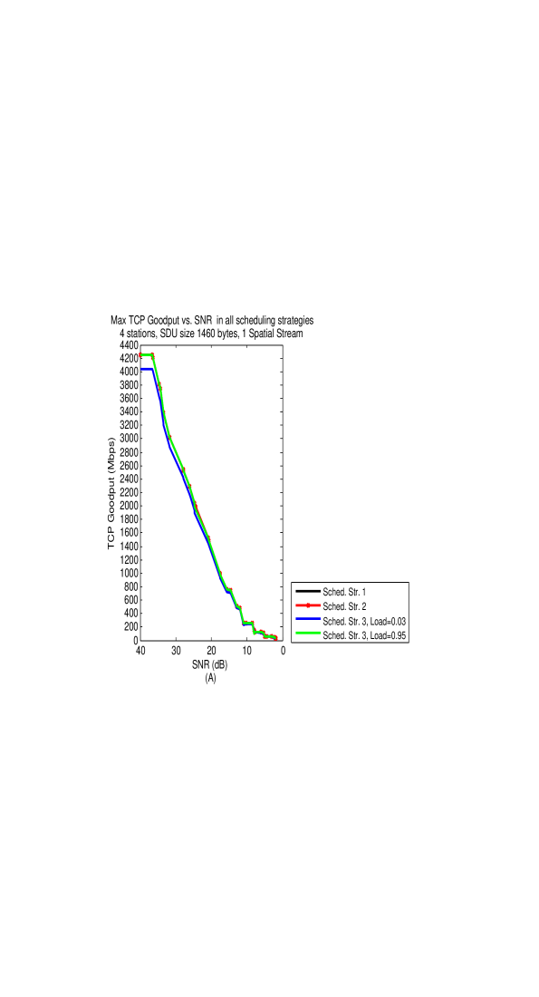
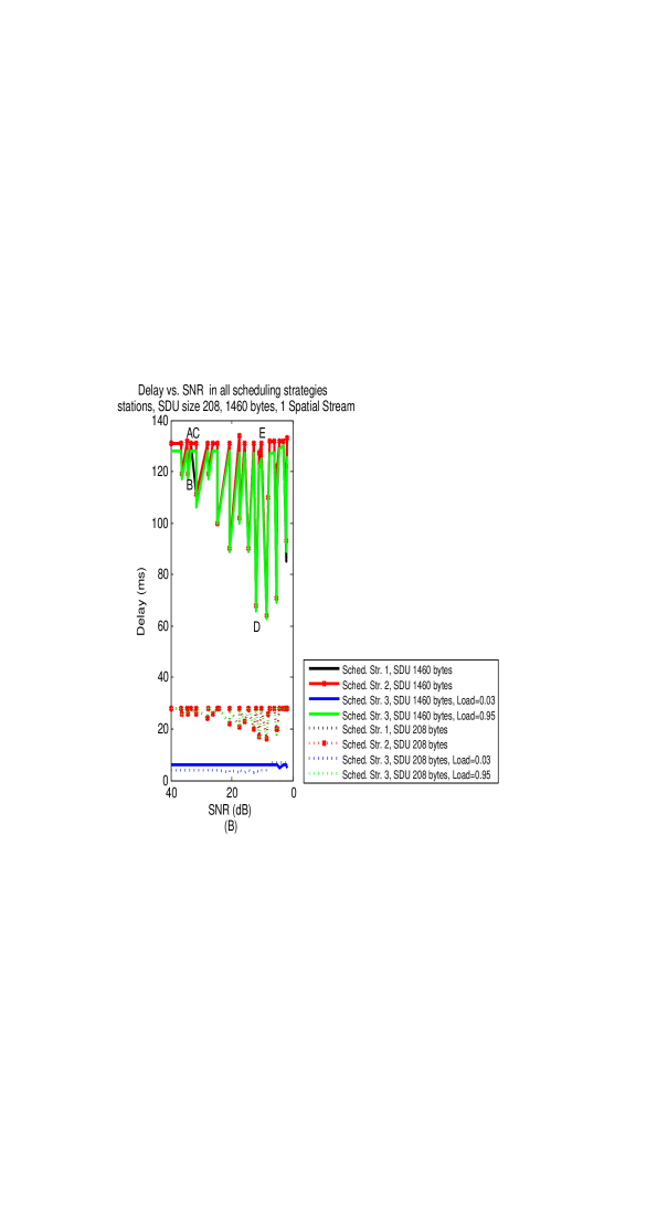
In Figure 3 we show the TCP Goodput and Delay results for 4 stations, i.e. one 160MHz channel, and for TCP Data segments of 1460 bytes. In Figures 3(A) and 3(B) we show the maximum TCP Goodput and Delay results respectively as a function of the SNR for scheduling strategies 1, 2 and 3, where for scheduling strategy 3 we assume loads of 0.03 and 0.95 .
It is clear from the figures that scheduling strategy 3 with load=0.03 is the best to use in terms of Delay optimization because it achieves about of the maximum TCP Goodput of the other strategies, but with a delay of , compared to about in the other strategies which all have a similar performance.
Notice that the Delay curves in Figure 3(B) are swinging, except for the case of scheduling strategy 3 with load=0.03 . The reasons for this swinging in the curves are subtle. Notice points A and B in the curves. For point A, which corresponds to SNR36.6, one uses MCS11 over both the DL and the UL with PHY rates of 1201.0 and 1134.2 Mbps respectively, and both channels are reliable, i.e. BER0. On the other hand, point B corresponds to SNR36.5 where the BER over the DL is 0.0006 using MCS11. Since we require a reliable UL channel one needs to use MCS10 over the UL with a PHY rate of 1020.8 Mbps. Thus, a smaller number of TCP Ack segments can be transmitted in one HE UL MU TCP Ack cycle, and this results in a smaller number of HE DL MU TCP Data cycles in the TXOP, and in a smaller Delay.
In point C the Delay increases again. Point C corresponds to SNR34.7 where MCS10 is used over both the DL and the UL with BER0. The number of TCP Acks to transmit in a TXOP remains as in point B but the DL PHY rate is smaller, which causes the TXOP to be longer compared to point B. Worth mentioning is also point D where the UL PHY rate becomes very small, 68.1 Mbps when using MCS0. This small PHY rate causes a small number of TCP Ack segments to be transmitted in a TXOP, and so also to a small number of TCP Data segments in a TXOP. At this point MCS1 is used over the DL with a PHY rate of 144.1 Mbps. There is an increase in the Delay in point E because at this point MCS0 is used over both the DL and the UL with a PHY rate of 68.1 Mbps over both channels. This results in a longer TXOP that is used to transmit the same number of TCP Data/TCP Ack segments as in point D.
There are no visible fluctuations in the curve for scheduling strategy 3 with load0.03 because the number of TCP Data segments to transmit in a TXOP is relatively small, and the differences in the PHY rates used over the SNR range cause differences only in the order of a few tenth of , which are not visible in the graph.
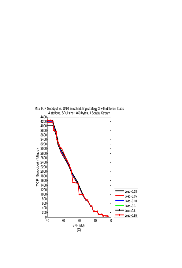
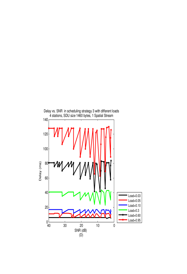
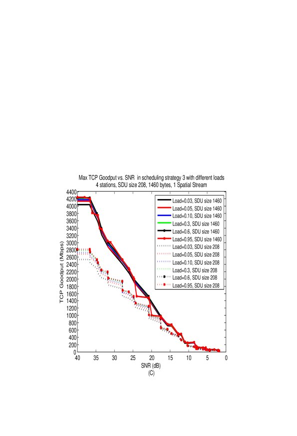
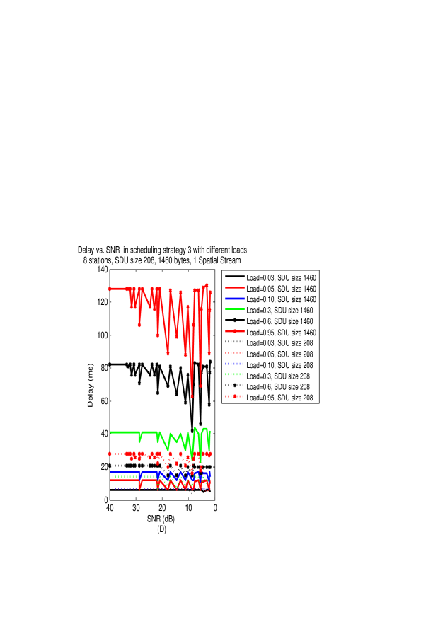
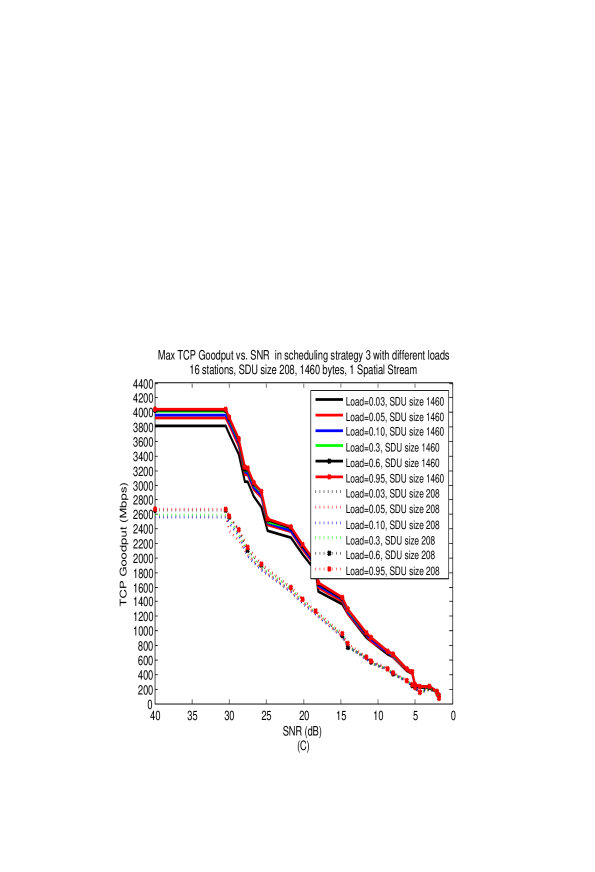
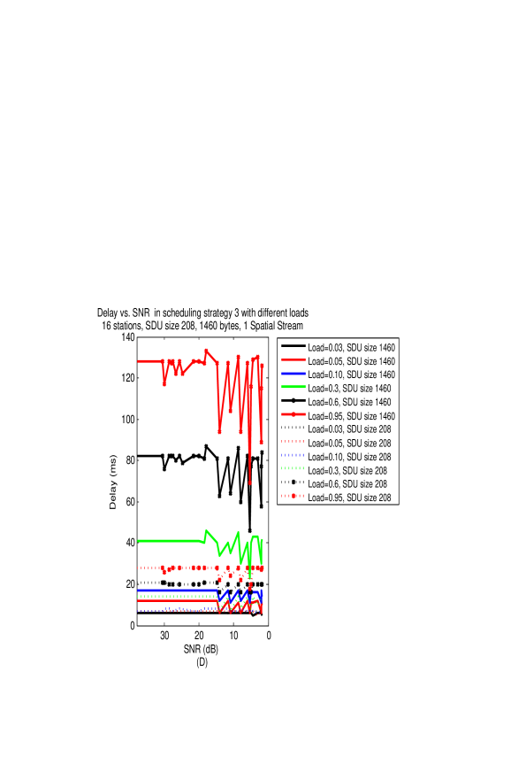
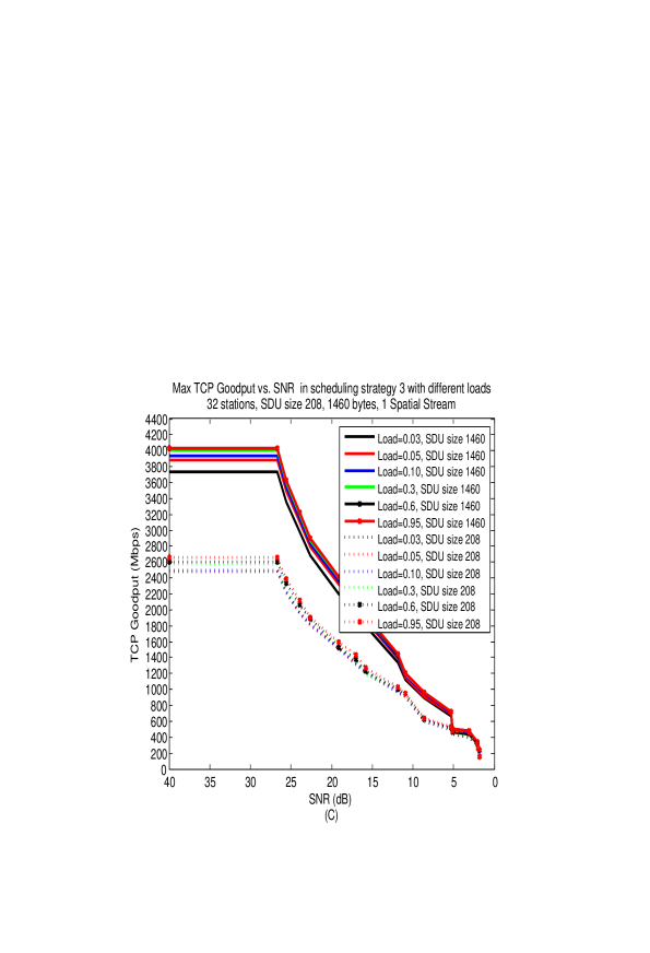
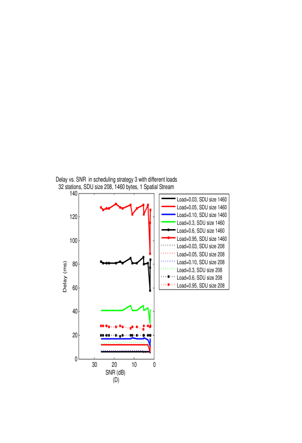
In Figures 3(C) and 3 (D) we show the sensitivity analysis of the load parameter in scheduling strategy 3 on the TCP Goodput and Delay results respectively. One can see that up to load0.1 the delays remain small while for larger loads the delay increases significantly without any gain in TCP Goodput, as can be observed from Figure 3(C).
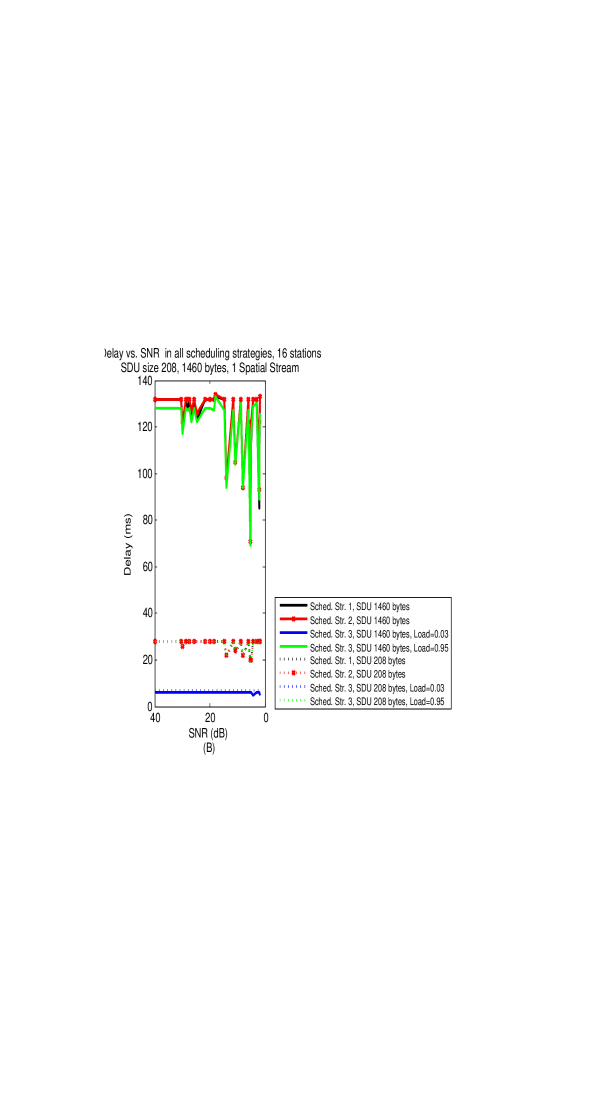
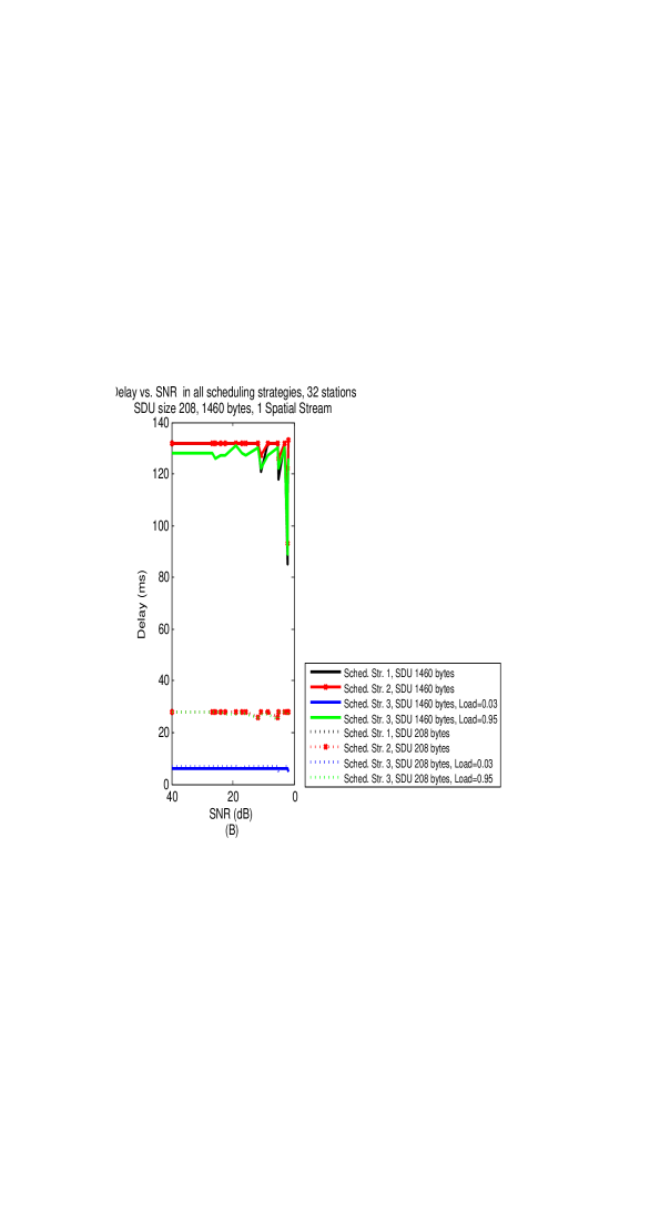
In Figure 4 we show the same results as in Figure 3 but this time for TCP Data segments of 208 and 1460 bytes together. For large SNR values the TCP Goodput results for TCP Data segments of 208 bytes are smaller than those for 1460 bytes. In both cases approximately the same number of TCP Ack segments are transmitted in a TXOP, but in the case of the short TCP Data segments the overhead (BackOff, AIFS etc.) is amortized over a smaller number of TCP Data bits, resulting in a lower TCP Goodput.
As the SNR decreases the TCP Goodputs in both segments’ sizes converge. As the SNR decreases so do the DL and UL PHY rates. This results in long transmission times of the TCP Data segments for both TCP Data segments’ sizes and the difference in length between 208 and 1460 bytes becomes less dominant.
Concerning the Delay metric, in general the TXOPs containing TCP Data segments of 208 bytes are shorter compared to those containing similar numbers of TCP Data segments of 1460 bytes. Therefore the delays are smaller in the former case. An exception is scheduling strategy 3 with load0.03, as we explain in relation to Figure 8 later. Scheduling strategy 3 with load0.03 is the most efficient in both segments’ sizes.
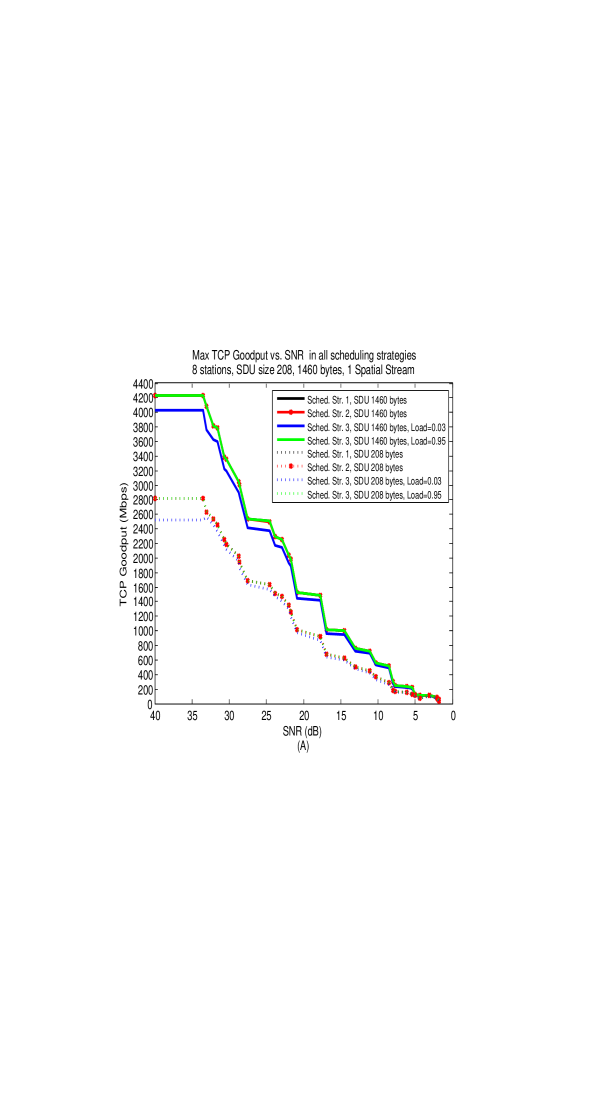
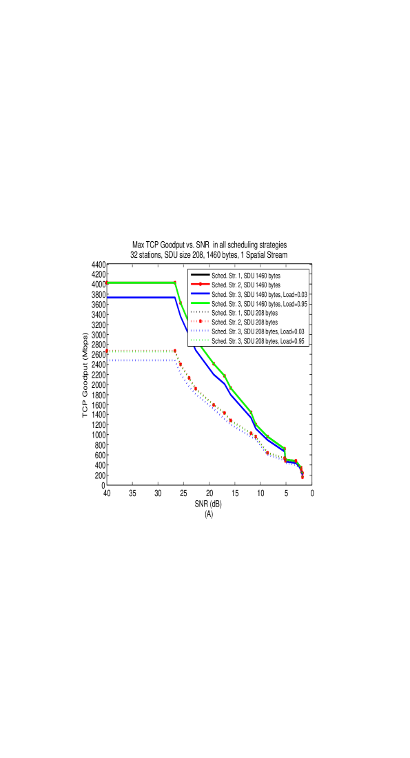
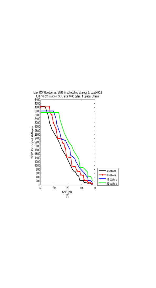
In Figures 5-7 we show the same results as in Figure 4 for 8, 16 and 32 stations, i.e. 80, 40 and 20MHz RUs respectively. The relative results among the scheduling strategies remain the same as in Figure 4. Worth mentioning is that the RU allocations of 160 and 80 MHz have a slightly larger maximum TCP Goodput than in RU allocations of 40 and 20 MHz. This is explained by the PHY rates shown in Table 1. A RU allocation of 80 MHz has half the PHY rate of that of a RU of 160 MHz and this is also the case for RUs of 20 and 40 MHz respectively. However, a RU of 40 MHz has less than half the PHY rate than that of a RU of 80 MHz.
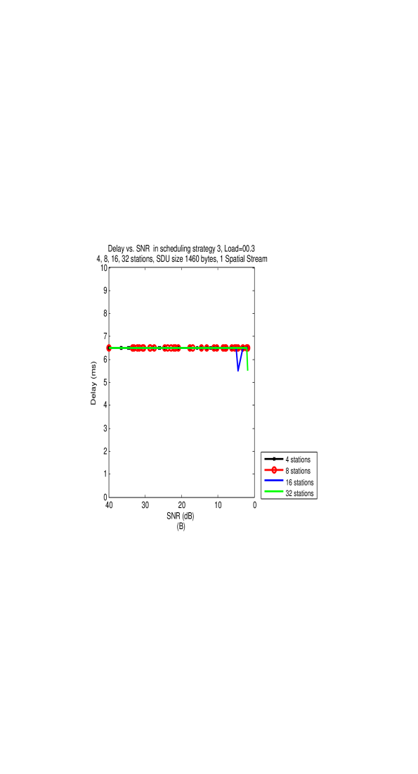
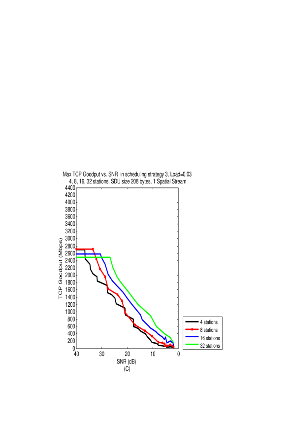
In Figure 8 we show the TCP Goodput and Delay results for scheduling strategy 3 with load0.03 only, as a function of the SNR. Results are shown for 4, 8, 16 and 32 stations, and for both sizes of TCP Data segments, to further check the impact of the number of stations on the TCP Goodput and Delay. As was observed before in RUs of 40 and 20 MHz there is a slightly lower TCP Goodput than in RUs of 160 and 80 MHz. Concerning the Delay metric, the Delays in the case of 208 and 1460 bytes TCP Data segments are the same over all the channels’ bandwidths.
Notice the Delay metrics in the cases of TCP Data segments of 1460 and 208 bytes in Figures 8(B) and 8(D) respectively. The delay in the case of TCP Data segments of 1460 bytes is smaller than that of 208 bytes: vs. . One might think that as the TCP Data segments are longer, so are the TXOPs and the Delay metric. However, in load0.03 only one PPDU is needed for the transmission of all the TCP Data segments. Since we assume that the AP transmits the minimum between the load and the number of TCP Data segments possible in one PPDU, the AP transmits more TCP Data segments of 208 bytes than TCP Data segments of 1460 bytes. Thus, more TCP Acks are transmitted in one TXOP in the case of TCP Data segments of 208 bytes, and so the TXOPs in this case are also slightly longer.
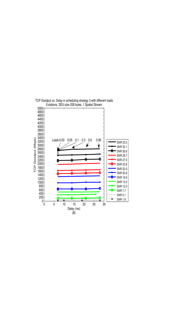
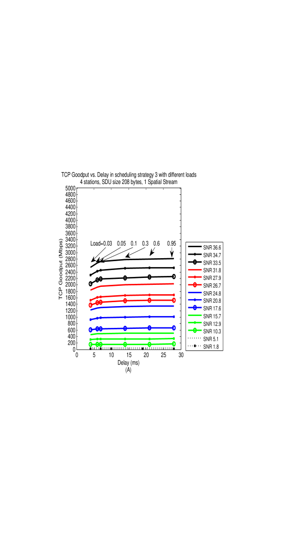
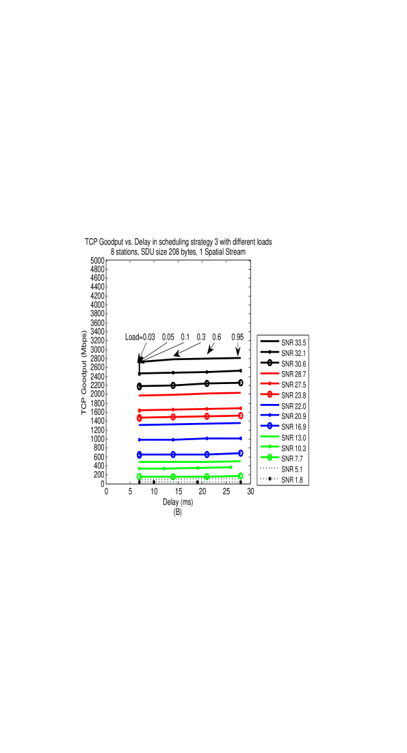
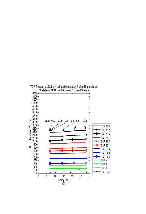
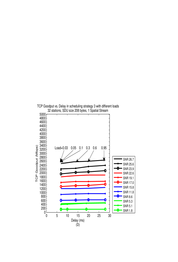
In Figures 9 and 10 we show the impact of the Delay, i.e. length of the TXOPs on the received TCP Goodput in different SNRs or MCSs in use. Figures 9 and 10 correspond to TCP Data segments of 1460 and 208 bytes respectively. The Delay metric can be a parameter in scheduling strategy 3 where the load determines the TXOPs length. In Figure 9(A), (B), (C) and (D) results are shown for RU allocation for 4, 8, 16 and 32 stations respectively. One can see that the maximum TCP Goodput is already received around Delays of 25ms. Thus, for overloaded TCP connections and long TCP Data segments RTTs of 25ms are sufficient to use the 11ax channel efficiently. For TCP Data segments of 208 bytes the sufficient Delay is about 13ms, Figure 10.
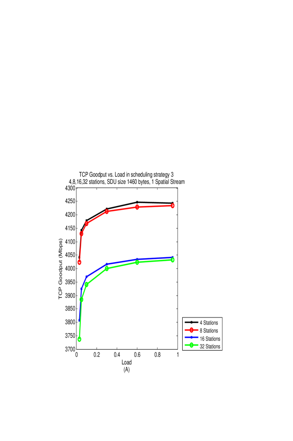
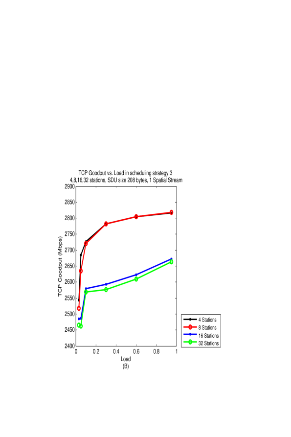
Finally, in Figure 11 we show the TCP Goodput vs. load in scheduling strategy 3 for 4, 8, 16 and 32 stations and for TCP Data segments of 208 and 1460 bytes. For TCP Data segments of 1460 bytes and when using load0.03 for all the number of stations, one only loses about of the maximum Goodput . When TCP Data segments are of 208 bytes one loses about . The difference between to is due to the fact that when short TCP Data segments are transmitted, more of them are needed to receive a good relation between the TCP Data bits transmitted and the overhead.


5 Summary
In this paper we suggest TCP-aware scheduling strategies for the transmission of unidirectional TCP traffic between the AP and the stations in an IEEE 802.11ax BSS. The AP is the source of TCP Data segments and the stations reply with TCP Acks. Our proposed TCP-aware scheduling strategies take advantage of MU transmission capability over the Uplink, which is a feature first introduced in IEEE 802.11ax .
Our TCP-aware scheduling strategies are based on TXOP; the selected MCSs used over the Uplink ensure reliable transmissions while the Downlink is unreliable. We measure the Goodput and TXOPs’ length in different transmission strategies that determine the TXOP formation that controls how many TCP Data segments are transmitted in a cycle.
Our main finding is that relatively short TXOPs cycles are sufficient to receive almost the largest Goodput, and there is a parameter for TXOP formation by which one can control what Goodput to receive, while paying in the TXOP cycle length. The TXOP cycle length is important since it is a part of the time-out measured by TCP. For example, we checked the Goodput and cycles’ length for 1460 and 208 bytes TCP Data segments’ length. In order to receive the largest Goodput one needs cycles of and respectively. If one loses of the maximum Goodput, the cycles’ length can decrease to .
Further research issues concerning TCP traffic over IEEE 802.11ax can be to explore the transmission of TCP data traffic from the stations to the AP and transmitting bidirectional TCP data traffic. Also, a small transmission error probability over the Uplink can be achieved by using large indexed MCSs which enable large PHY rates, while on the other hand using shorter MPDUs and so transmitting a smaller number of TCP Acks. It is interesting to check if such a scheme is more efficient than the one used in this paper where lower indexed MCSs ensure a reliable Uplink with lower PHY rates.
6 Appendix
In this appendix we demonstrate the relation between the channel bandwidth, MCS in use and the SNR to the received BER in various RUs’ bandwidths and MCSs in use. The results are taken from [40]. We assume that the AP is communicating with every station over one spatial stream.
In Table 2 we show some examples for this relation, assuming the 160MHz channel RU allocation. For example, for the BER equals 0 for all the MCSs and clearly in this case both the AP and the stations use MCS11 over the DL and the UL respectively, which enables the largest PHY rate. For one can assume that either the AP uses MCS11 and the stations use MCS10, or both the AP and the stations use MCS10. Recall that in this paper we assume that the channel over which the TCP Acks are transmitted, i.e. the UL, is reliable, and so in SNR35.1 the stations cannot use MCS11 over the UL. Notice that the AP can use either MCS11 or MCS10 over the DL, with a trade-off: the first possibility is a larger PHY rate but BER0, while the other possibility is the PHY rate is smaller but BER0.
In Table 2 we also show the most efficient MCSs to use for every SNR (in terms of the Goodput) over the DL and UL. These MCSs are shown in Italic. For example, for SNR36.6 dB MCS11 is used over the DL and the UL. For SNR35.1 dB MCS11 is used over the DL and MCS10 is used over the UL. Notice also that when considering a 160MHz channel RU allocation, such a channel can be used for SNRs larger than 10.2 dB only.
| SNR | MCS | |||||||||||
|---|---|---|---|---|---|---|---|---|---|---|---|---|
| 0 | 1 | 2 | 3 | 4 | 5 | 6 | 7 | 8 | 9 | 10 | 11 | |
| 36.6 | 0 | 0 | 0 | 0 | 0 | 0 | 0 | 0 | 0 | 0 | 0 | 0 |
| 35.1 | 0 | 0 | 0 | 0 | 0 | 0 | 0 | 0 | 0 | 0 | 0 | 0.6595 |
| 34.0 | 0 | 0 | 0 | 0 | 0 | 0 | 0 | 0 | 0 | 0 | 0.0222 | 1 |
| 33.6 | 0 | 0 | 0 | 0 | 0 | 0 | 0 | 0 | 0 | 0 | 0.3696 | 1 |
| 33.5 | 0 | 0 | 0 | 0 | 0 | 0 | 0 | 0 | 0 | 0.0005 | 0.4958 | 1 |
| 32.5 | 0 | 0 | 0 | 0 | 0 | 0 | 0 | 0 | 0 | 0.0987 | 1 | 1 |
| 31.7 | 0 | 0 | 0 | 0 | 0 | 0 | 0 | 0 | 0 | 0.9412 | 1 | 1 |
| 30.2 | 0 | 0 | 0 | 0 | 0 | 0 | 0 | 0 | 0.6457 | 1 | 1 | 1 |
| 27.1 | 0 | 0 | 0 | 0 | 0 | 0 | 0 | 0.0749 | 1 | 1 | 1 | 1 |
| 25.9 | 0 | 0 | 0 | 0 | 0 | 0 | 0.0022 | 1 | 1 | 1 | 1 | 1 |
| 24.7 | 0 | 0 | 0 | 0 | 0 | 0.0010 | 0.832 | 1 | 1 | 1 | 1 | 1 |
| 20.1 | 0 | 0 | 0 | 0 | 0.1417 | 1 | 1 | 1 | 1 | 1 | 1 | 1 |
| 19.7 | 0 | 0 | 0 | 0 | 0.5970 | 1 | 1 | 1 | 1 | 1 | 1 | 1 |
| 17.5 | 0 | 0 | 0 | 0.0005 | 1 | 1 | 1 | 1 | 1 | 1 | 1 | 1 |
| 16.4 | 0 | 0 | 0 | 0.4973 | 1 | 1 | 1 | 1 | 1 | 1 | 1 | 1 |
| 14.6 | 0 | 0 | 0.0003 | 1 | 1 | 1 | 1 | 1 | 1 | 1 | 1 | 1 |
| 13.6 | 0 | 0 | 0.4188 | 1 | 1 | 1 | 1 | 1 | 1 | 1 | 1 | 1 |
| 10.2 | 0 | 1 | 1 | 1 | 1 | 1 | 1 | 1 | 1 | 1 | 1 | 1 |
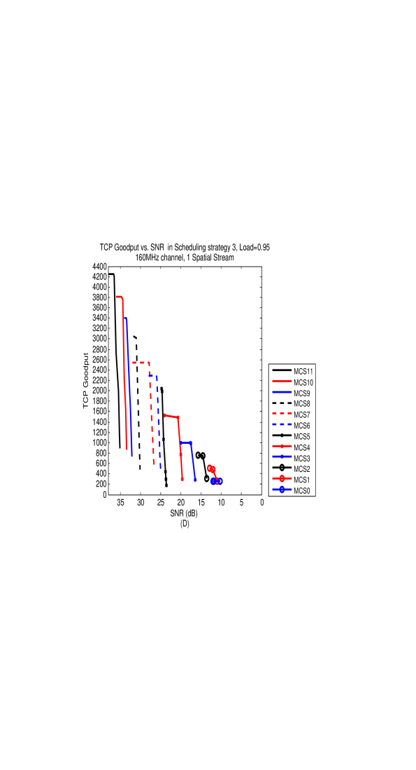
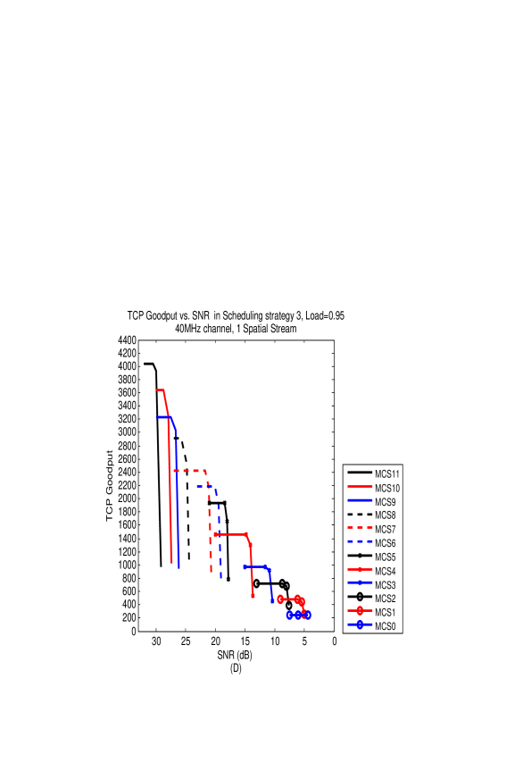
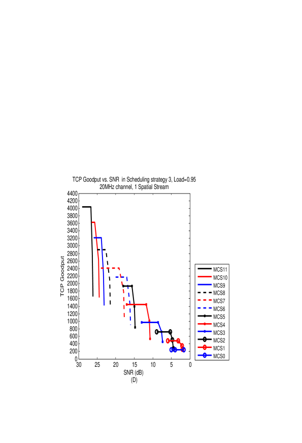
In Figure 12 we show for the four RU allocation channels in use in this paper, namely 160, 80, 40 and 20 MHz, and for scheduling strategy 3 with , the received TCP Goodput as a function of the SNR. We assume TCP Data segments of 1460 bytes. The curves are generated based on raw data from [40] and are ’waterfall’ shaped. One can see that every MCS has a range of SNR values over which it enables a positive TCP Goodput. The lower indexed MCSs can be used in lower SNRs, but with a smaller PHY rate and so with a smaller TCP Goodput.

References
- [1] IEEE Std. 802.11TM-2016, IEEE Standard for Information Technology - Telecommunications and Information Exchange between Systems - Local and Metropolitan Area Networks - Specific Requirements. Part 11: Wireless LAN Medium Access Control (MAC) and Physical Layer (PHY) Specifications, IEEE, NewYork, (December 2016)
- [2] IEEE P802.11axTM/D1.4, IEEE Draft Standard for Information Technology - Telecommunications and Information Exchange between Systems - Local and Metropolitan Area Networks - Specific Requirements. Part 11: Wireless LAN Medium Access Control (MAC) and Physical Layer (PHY) Specific requirements. IEEE, NewYork, (2017)
- [3] IEEE Std. 802.11acTM-2013, IEEE Standard for Information Technology - Telecommunications and Information Exchange between Systems - Local and Metropolitan Area Networks - Specific Requirements. Part 11: Wireless LAN Medium Access Control (MAC) and Physical Layer (PHY) Specific requirements. Amendment 4: Enhancements for Very High Throughput for Operation in Bands below 6 GHz, IEEE, NewYork, (2013)
- [4] E. Perahia, R. Stacey, Next Generation Wireless LANs: 802.11n and 802.11ac, 2nd Edition, Cambridge Press, 2013
- [5] E. Khorov, A. Kiryanov, A. Lyakhov, IEEE 802.11ax: How to Build High Efficiency WLANs, Int. Conf. on Eng. and Telecommunication (2015) 14-19
- [6] M. S. Afaqui, E. G. Villegas, E. L. Aguilera, IEEE 802.11ax: Challenges and Requirements for Future High Efficiency WiFi, IEEE Wireless Communications 99 (2016) 2-9
- [7] D. J. Deng, K. C. Chen, R. S. Cheng, IEEE 802.11ax: Next Generation Wireless Local Area Networks, 10th Int. Conf. on Heterogeneous Networking for Quality, Security and Robustness (QSHINE), (2014) 77-82
- [8] B. Bellalta, IEEE 802.11ax: High-efficiency WLANs, IEEE Wireless Communications, 23(1) (2016) 38-46
- [9] O. Sharon, Y. Alpert, Scheduling strategies and Throughput optimization for the Uplink for IEEE 802.11ax and IEEE 802.11ac based networks, Wireless Sensor Networks,9 (2017) pp. 250-273
- [10] O. Sharon, Y. Alpert, Scheduling strategies and throughput optimization for the Downlink for IEEE 802.11ax and IEEE 802.11ac based networks, Submitted, Physical Communications
- [11] O. Sharon, Y. Alpert, Single User MAC level Throughput comparision: IEEE 802.11ax vs. IEEE 802.11ac, Wireless Sensor Networks, 9 (2017), pp. 166-177
- [12] B. Bellalta, K. Kosek-Szott, AP-initiated Multi-User Transmissions in IEEE 802.11ax WLANs, arXiv:1702.05397v1 [cs.NI] (2017)
- [13] O. Sharon, Y. Alpert, Optimizing TCP Goodput and Delay in next generation IEEE 802.11 (ax) devices, Submitted Ad-Hoc Networks
- [14] R. Karmakar, S. Chattopadhyay, S. Chakraborty, Impact of IEEE 802.11n/ac PHY/MAC High Throughput Enhancement over Transport/Application layer protocols - A Survey, IEEE Communication surveys and tutorials (2017)
- [15] Miorandi, D., Kherani, A. A. and Altman, E. (2006) A Queueing model for HTTP traffic over IEEE 802.11 WLANs. Computer Networks, 50, 63-79.
- [16] Bruno, R., Conti, M. and Gregori, E. (2005) Throughput Analysis of UDP and TCP Flows in IEEE 802.11b WLANs: A Simple Model and its Validation. Workshop on Techniques, Methodologies and Tools for Performance Evaluation of Complex Systems, 2005, 54-63.
- [17] Bruno, R., Conti, M. and Gregori, E. Throughput Analysis and Measurements in IEEE 802.11 WLANs with TCP and UDP Traffic Flows. IEEE Trans. on Mobile Computing, 7, 171-186, (2008)
- [18] Kumar, A., Altman, E., Miorandi, D. and Goyal, M. New Insights from a Fixed Point Analysis of Single Cell IEEE 802.11 WLANs. IEEE/ACM Trans. on Networking, 15, 588-601, (2007)
- [19] D. Chen, A survey of IEEE 802.11 Protocols: Comparison and Prospective 5th International Conference on Mechatronics, Materials, Chemistry and Computer Engineering (ICMMCCE) pp. 569-578, (2017)
- [20] H. A. Omar, K. Abboud, A Survey on High Efficiency Wireless Local Area Networks: Next Generation WiFi, IEEE Communications Surveys and Tutorials, (2016)
- [21] D. Nandal, P. Yadav, A Review on OFDMA and MU-MIMO MAC Protocols for upcoming IEEE Standard 802.11ax International Journal on Recent and Innovation Trends in Computing and Communication, Vol. 4, Issue 8, pp. 108-114 (2016)
- [22] Q. Qu, B. Li, M. Yang, Z. Yan, An OFDMA based Concurrent Multiuser MAC for Upcoming IEEE 802.11ax, IEEE Wireless Comm. and Networking Conf. Workshops (WCNCW) pp. 136-141, (2015)
- [23] D.J. Deng, S. Y. Lien, J, Lee, K. C. Chen, On Quality-of-Service Provisioning in IEEE 802.11ax WLANs IEEE Access, Vol. 4, pp. 6086-6104 (2016)
- [24] A. Aijaz, P. Kulkarni, Simultaneous Transmit and Receive Operation in Next Generation IEEE 802.11 WLANs: A MAC Protocol Design Approach IEEE Wireless Communications Vol. 24, No. 6, pp. 128-135 (2017)
- [25] R. Pierre, F. Hoefel, IEEE 802.11ax: On Time Synchronization in Asynchronous OFDM Uplink Multi-User MIMO Physical Layer, XXXV Simposio Brasileiro De Telecomunicacoes E Processamento De Sinais-Sbr (2017)
- [26] W. Lin, B. Li, M. Yang, Q. Qn, Z. Yan, X. Zuo, B. Yang, Integrated Link-System level Simulation Platform for the Next Generation WLAN - IEEE 802.11ax, IEEE Globecom (2016)
- [27] J. Lee, D. J. Deng, K. C. Chen, OFDMA-based hybrid channel access for IEEE 802.11ax WLAN, unpublished.
- [28] M. Karaca, S. Bastani, B. E. Priyanto, M. Safavi, B. Landfeldt, Resource Management for OFDMA based Next Generation 802.11ax WLANs, 9th IFIP Wireless and Mobile Networking Conf. (WMNC) (2016)
- [29] V. Jones, H. Sampath, Emerging technologies for WLAN, IEEE Commu. Mag., 5 (2015) 141-9
- [30] L. Sanabria-Russo, A. Faridi, B. Bellalta, J. Barcelo, M. Oliver, Future evolution of CSMA protocols for the IEEE 802.11 standard IEEE Int. Conf. on Comm. (ICC) (2013) 1274-9
- [31] L. Sanabria-Russo, J. Barcelo, A. Faridi, B. Bellalta, WLANs throughput improvement with CSMA/ECA, IEEE Conf. on Computer Comm. Workshops (INFOCOM WKSHPS) (2014) 125-6
- [32] Y. He, R. Yuan, J. Sun, W. Gong, Semi-Random Backoff: Towards resource reservation for channel access in wireless LANs, IEEE Int. Conf. on Network Protocols (ICNP) (2009) 21-30
- [33] E. Khorov, V. Loginov, A. Lyakhov, Several EDCA Parameters Sets for Improving Channel Access in IEEE 802.11ax Networks, Int. Symposium on Wireless Communication Systems (ISWCS) (2016) 419-423
- [34] O. Sharon, Y. Alpert, Coupled IEEE 802.11ac and TCP performance evaluation in various aggregation schemes and Access Categories, Computer Networks 100 (2016) 141-156
- [35] O. Sharon, Y. Alpert, Coupled IEEE 802.11ac and TCP Goodput improvement using Aggregation and Reverse Direction, Wireless Sensor networks 8(7) (2016) 107-136
- [36] O. Sharon, Y. Alpert, Comparison between TCP scheduling strategies in IEEE 802.11ac based Wireless networks, Ad Hoc Networks 61C (2017) pp. 95-113
- [37] O. Sharon, Y. Alpert, MAC level Throughput comparison: 802.11ac vs. 802.11n, Physical Communication 12 (2014) 33-49
- [38] IEEE Std. 802.11TM-2012, Standard for Information Technology - Telecommunications and Information Exchange between Systems - Local and Metropolitan Area Networks - Specific Requirements. Part 11: Wireless LAN Medium Access Control (MAC) and Physical Layer (PHY) specifications, IEEE, NewYork, (2012)
- [39] O. Sharon, Y. Alpert, The combination of aggregation, ARQ, QoS guarantee and mapping of Application flows in very High Throughput 802.11ac networks, Physical Communication 17 (2015) 15-36
- [40] IEEE P802.11 Wireless LANs, 11ax Evaluation Methodology, Appendix 3 - RBIR and AWGN PER Tables (2015) .