Software-based discharge suppressor using an EPICS data acquisition system as a rapid prototype at the LIPAc beam extraction system
Abstract
Internal continuous discharge can rapidly damage high-current ion sources and their extraction systems composed of several electrodes at high voltage. To prevent this continuous discharge inside the extraction system, a rapid prototype using an Experimental Physics and Industrial Control System (EPICS) software system for data acquisition has been implemented. During commissioning of the 140 mA deuterium electron cyclotron resonance ion source of the Linear IFMIF Prototype Accelerator (LIPAc), discharges were often observed during plasma tuning of the ion source and beam optics tuning of the extraction system. If such continuous discharge can be avoided, discharge-related damage such as melting electrode edges and holes in the boron nitride disk in the ion source can be minimized and thus an efficient machine operation can be achieved. A veto signal is output to the machine protection system, which is then in charge of the RF power shutdown of the ion source for a pre-determined time. The average reaction time of this system has been measured and is about 10 ms from discharge detection to RF power shutdown of the ion source with a 50 Hz sampling frequency. This is hundreds of times slower than hardware-based implementation. However, it prevents almost all continuous discharges at the LIPAc ion source and extraction system, and is still much faster than an operator’s reaction time.
I Introduction
The Linear IFMIF Prototype Accelerator (LIPAc) is a prototype accelerator to demonstrate 125 mA/9 MeV continuous-wave (CW) deuterium accelerator technologies Knaster_LIPAc . Its objective is to realize an accelerator-driven neutron source: the International Fusion Materials Irradiation Facility (IFMIF) that provides neutron equivalent spectrum of deuterium–tritium fusion reactions and delivers adequate () neutron flux to test materials to be used in future commercial fusion reactors Knaster_IFMIF .
To realize this 100 mA class CW hadron accelerator, the ion source of LIPAc is required to produce low beam emittance (maximum value of ) at the radio-frequency quadrupole (RFQ) entrance with well-matched Twiss parameters to minimize beam losses to less than 10% through the RFQ Michele . These two points are to avoid damages during operation on downstream accelerator components and on the injector itself. A previous study showed that a boron nitride (BN) lining increases atomic ion fraction ChalkRiver_1991 . Therefore, the ion source of LIPAc employs a set of BN lining disks.
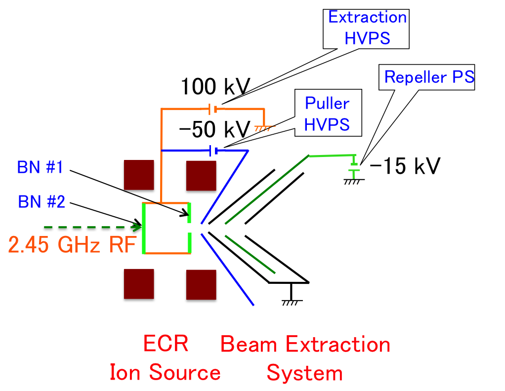
The injector of LIPAc is composed of a 2.45 GHz electron cyclotron resonance (ECR) ion source based on the CEA-Saclay SILHI source design SILHI and a low energy beam transport (LEBT) line to transport and match the beam into the RFQ using a dual solenoid focusing system with integrated steerers. Figure 1 shows the LIPAc ECR ion source and its five-electrode beam extraction system in the accelerator column structure, while Table 1 shows the required beam parameters at the exit of the LIPAc injector Gobin_LIPAc , Delferriere_LIPAc . The LIPAc ion source uses an injection of gases ( and ), a 2.45 GHz 1000 W magnetron RF generator, and two solenoids to generate plasma. To obtain optimum beam optics, a puller electrode is used in addition to a plasma electrode. A negative potential electrode (called a repeller) is inserted between two ground electrodes to prevent electron invasion into the ion source.
| Particle type | D+ |
|---|---|
| D+ fraction | 99% |
| Beam energy | 100 keV |
| Beam current | 140 mA |
| Beam current noise | 1% rms |
| Duty factor | CW |
| (pulse for commissioning tests) | |
| Normalized rms transverse emittance |
II Discharge in the Beam Extraction System
II.1 Discharge phenomena and consequences
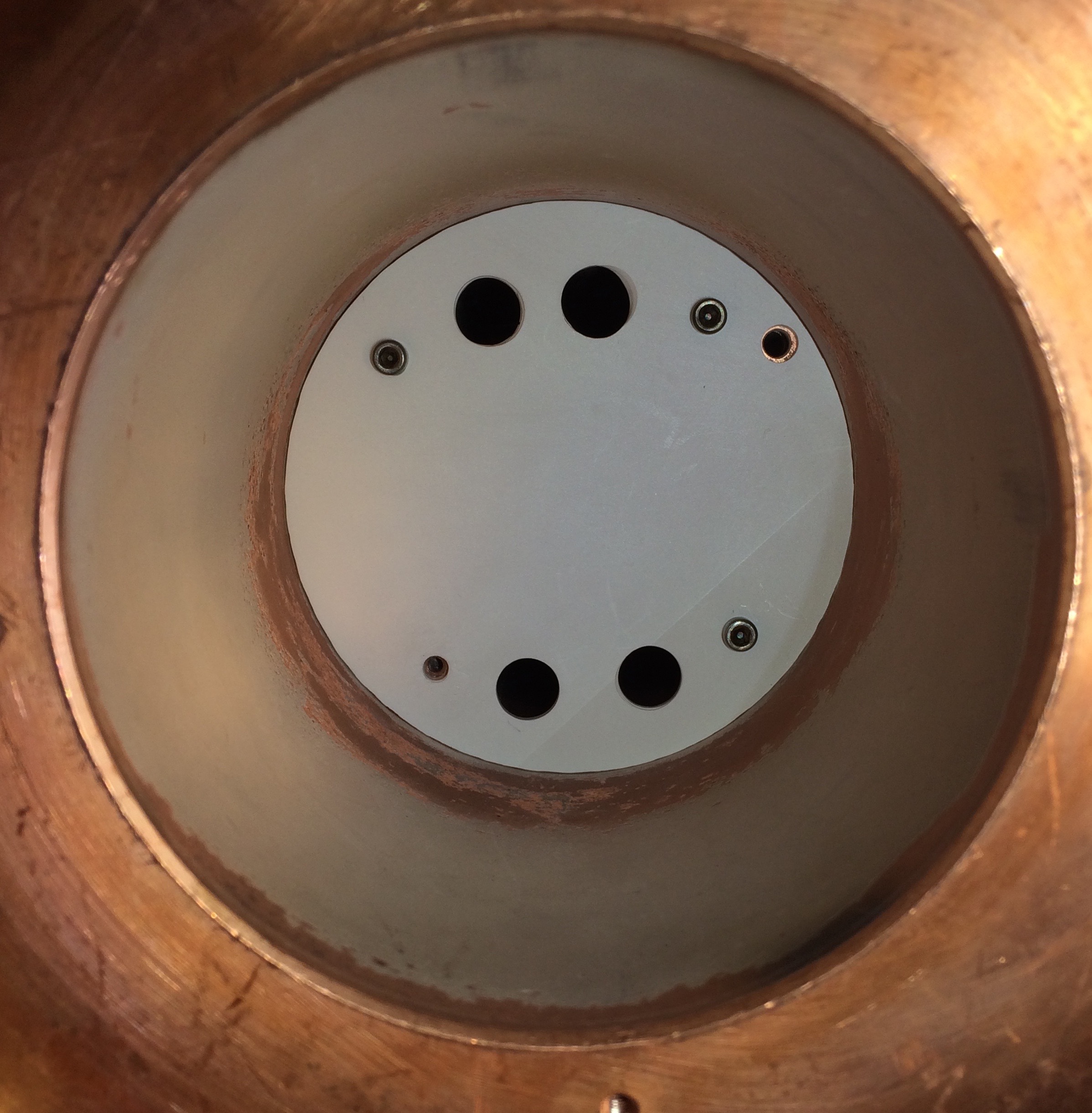
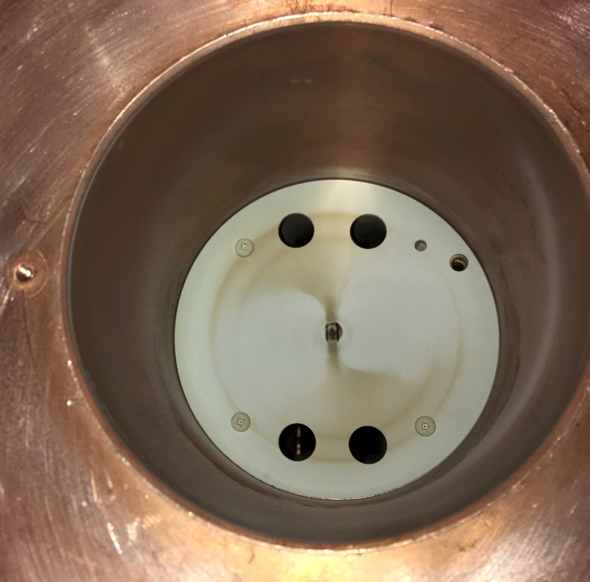
The beam from the ion source is injected into the LEBT line where many secondary electrons exist. They are produced by collision between the beam and residual gas footnote1 in the LEBT. They are also produced by the collision of the beam with other accelerator components located inside the LEBT. If some of these secondary electrons are attracted by the acceleration voltage, they rush into the ion source and damage it. They are therefore called back-streaming electrons. To prevent back-streaming electron invasion into the ion source, a repeller electrode is used (Figure 1 shows a repeller electrode installation). Applying a negative voltage to the repeller electrode creates a potential wall against the back-streaming electrons footnote2 . However, many high-current ion source facilities report damage or countermeasure of back-streaming electrons LEDA_1997 , PSI_2011 , IUCF_2004 , China_2008 . Figure 2 shows a new BN disk (BN #2 in Figure 1), and Figure 3 shows a damaged BN #2 disk in the LIPAc ion source. The central area is damaged, black colored, and slightly dipped. Once a hole is made, the performance is much reduced.
One possible scenario of this secondary electron invasion is that the secondary electrons are produced inside the extraction system itself. In fact, if the beam divergence becomes large in the extraction system due to bad beam optics, the beam can hit the electrodes (such as the puller electrode) of the extraction system. A large amount of secondary electrons can thus be produced, and they are then attracted to the ion source.
A second scenario is that the repeller electrode voltage decreases during operation and that the secondary electrons located in the LEBT then have sufficient energy to pass the potential of the repeller electrode. The drop in the repeller electrode voltage can be due to several reasons. For instance, it can be due to a Penning discharge between the repeller and one of the two ground electrodes, which is a consequence of electrons accelerated up to several kilovolts and trapped in one or several locations in the accelerator column by a combination of electric and magnetic field lines with enough energy to ionize the residual gas. The drop in the repeller electrode voltage can be also induced by collision of the beam with the repeller electrode. It has also been observed during LIPAc injector commissioning that a drop in the main high voltage (HV) sometimes induced a drop in the repeller electrode voltage, but more investigations are needed to understand such complex phenomena. External disturbances or bad grounding can also induce such a drop in the repeller electrode, as observed during the LIPAc injector commissioning.
To determine the minimum voltage to apply to the repeller electrode to repel all the secondary electrons from the LEBT, measurements of the emittance were performed with a 100 keV deuterium beam at the LIPAc injector as a function of the repeller electrode voltage (), see Figure 4.
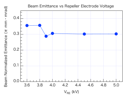
The emittance measurements were performed using an Allison scanner Allison installed just downstream of the extraction system. The results show that the emittance increases when the repeller electrode voltage is set below 3.9 kV. This observation shows that a minimum voltage of 3.9 kV on the repeller electrode is necessary to repel all the secondary electrons. If the voltage is just decreased by 100 V, the energy of the secondary electrons (same energy for all electrons) is then enough to pass the potential of the repeller electrode and all these electrons come back to the ion source. The emittance is thus increased as less secondary electrons are present to contribute to the space charge compensation of the beam. In addition, it was observed with an oscilloscope that the pulse of total extracted current was becoming unstable and that the level of this pulse was increasing for below 3.9 kV. The secondary electrons coming back to the source add a positive current to the extracted current and disturb the ion source.
II.2 Measurement of discharge at the LIPAc injector
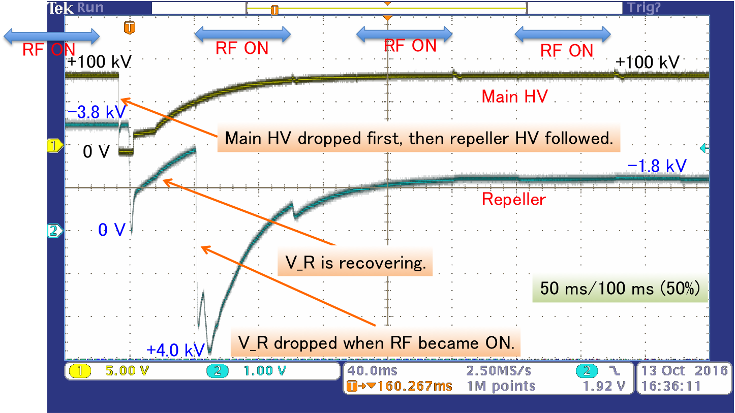
Figure 5 shows the main and repeller HV monitor voltage outputs at a typical discharge event at the LIPAc ion source. A discharge occurred during the time that the RF pulse was off. The main HV dropped to 0 V due to this discharge. About 5 ms later, the repeller HV also dropped. Both HV outputs were recovering to the nominal voltage until the next RF pulse was ON. When the next RF pulse was ON, an improper electric field in the extraction system induced a large divergence of the extracted beam and a certain amount of beam hit the repeller electrode. This induced a radical change in the repeller electrode potential, which became +4.0 kV. After this event, the repeller HV only partially recovered as it never returned to the nominal voltage of kV but stayed at kV. This voltage was not sufficient to repel the incoming back-streaming electrons as shown previously with the data of Figure 4. This state is harmful for the ion source. To protect the ion source and its extraction system, the RF pulse should be turned off immediately when discharge-related voltage drops are observed.
III Implementation of the Discharge Suppression System
The objective of the discharge suppression system was to mitigate abnormal conditions and downtime of the accelerator. The policy of this discharge suppressor system implementation is:
-
•
Implementation using the fast recovery mode of the machine protection system (MPS).
-
•
Minimum hardware implementation.
-
•
Reuse existing resources as much as possible.
-
•
Implementation of core logics by the Experimental Physics and Industrial Control System (EPICS) code (software) EPICS .
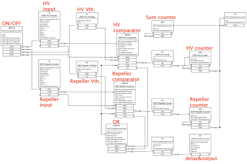
Figure 6 shows an overview of this discharge suppressor system. The elements of this system are represented inside the dashed rectangle. It continuously monitors voltage monitor outputs of the 100 kV high-voltage power supply (HVPS) and repeller HVPS. When its comparators detect a voltage drop for at least one monitor input, they send a pre-determined length of alert signal to the MPS input. The MPS system MPS_IPAC11 (below) stops the RF gate signal going to the RF generator of the ion source.
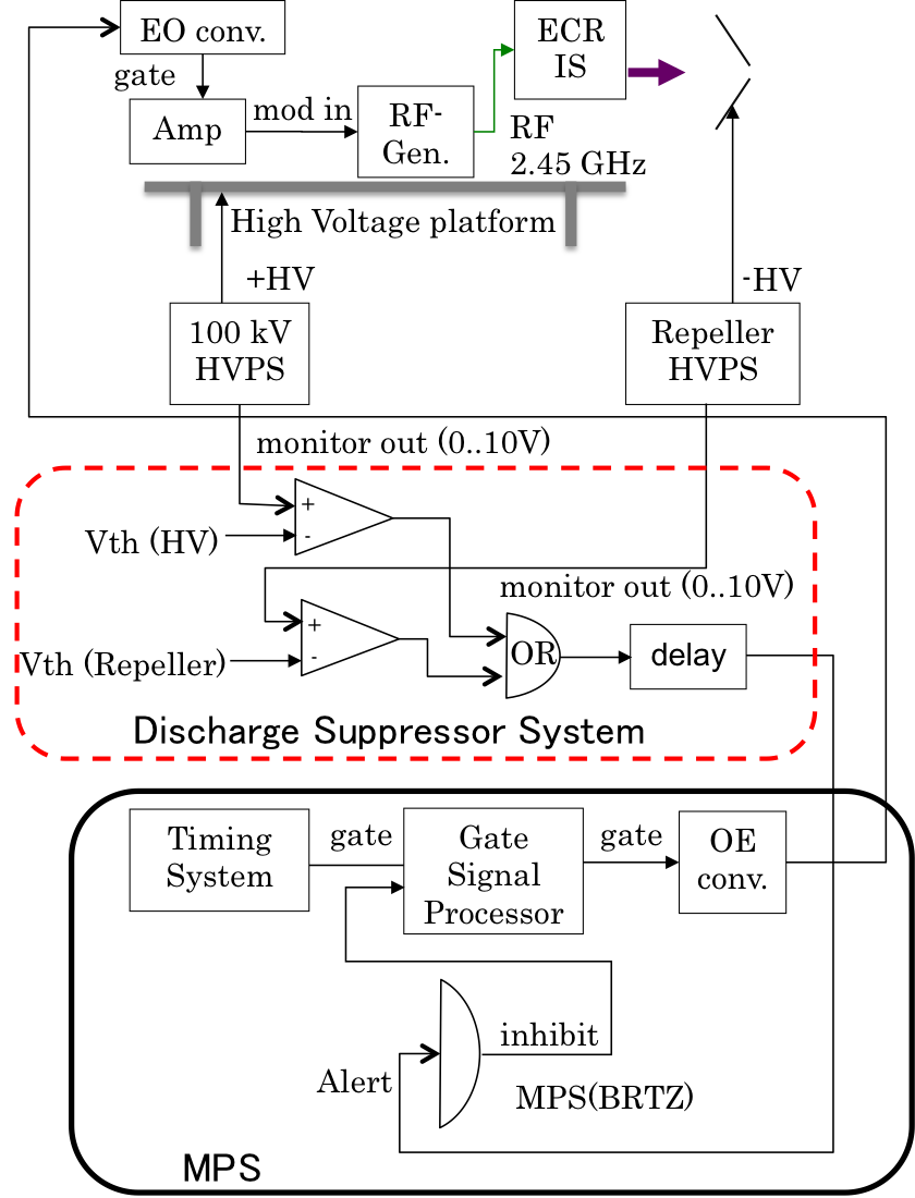
III.1 EPICS code implementation
All functionalities (Comparator, OR, and Delay) shown in Figure 6 except the MPS interface were implemented by the EPICS database (DB) system. Comparator, OR, and Event counter were implemented with calc or calcout records. Delay functionality was implemented with the function bo record (HIGH field). For further details, see the Appendix.
IV Results
Figure 7 shows typical behavior with activation of the discharge suppressor system. The blue (ch.2: V_Rep) line is the repeller HV monitor output voltage, the green (ch.4: V_HV) line is the 100 kV HV monitor output voltage, and the magenta (ch.3: I_HV) line is the total extraction current of the 100 kV HV power supply that corresponds to the beam output current from the ion source. The yellow line (ch1:I_FC) is the current measured with the Faraday cup located in the LEBT FaradayCup .
At the beginning of the second I_HV pulse, a 100 kV HV discharge occurred and its voltage dropped to 0 kV. The repeller HV (4.5 kV initially) dropped a few milliseconds later. This discharge suppression system prevented RF pulse injection (corresponding to the I_HV pulse) for 640 ms, and no further HV drops were observed. In fact, this time interval of 640 ms allows the main HV and repeller HV to fully recover before the next beam pulse is generated.
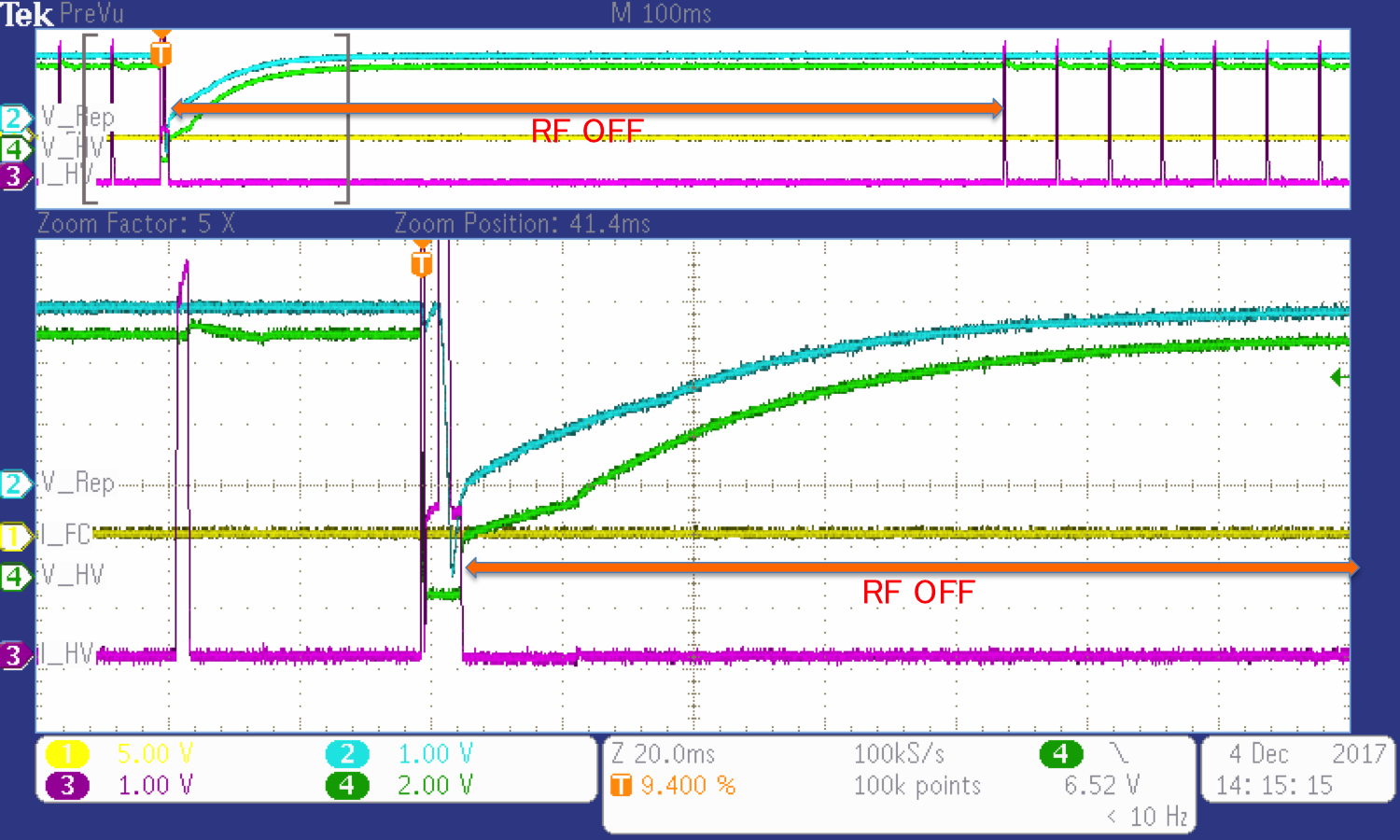
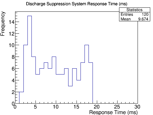
Figure 8 shows response time measurement of the discharge suppression system from the HV monitor drop to the MPS alert signal output. These data were obtained by injecting into the system a simulated repeller monitor drop signal and by measuring the input and output signal latency with an oscilloscope. The response time was randomly distributed from 1 ms to 19 ms.
The HV monitor output and repeller monitor output were independently sampled at 50 Hz and processed. Therefore, the dominant contribution of these response times was the sampling interval of the EPICS software. Generally, a minimum software sampling interval is determined by timer interruption period in the operating system. This means 50 Hz is the maximum sampling speed with the current VxWorks 6.9 real-time operating system VxWorks default configuration.
V Conclusion
Continuous discharge at the repeller electrode can cause invasion of back-streaming electrons into the ion source, which is then damaged. To prevent continuous discharge at the ion source and the extraction system, immediate shut-off of the ion source RF power is mandatory. To realize this required functionality, a software-based ion source and beam extraction system suppression system has been implemented and tested. This system was implemented with an existing VME-based EPICS data acquisition system. All functionalities were implemented with the EPICS DB system. It effectively prevented fatal continuous discharge. This system is relatively slow for software implementation, but it has demonstrated its ability to suppress continuous discharge efficiently.
acknowledgments
This work was carried out as part of the IFMIF/EVEDA project based on Broader Approach activities.
APPENDIX:DETAILS OF IMPLEMENTATION
As described in the EPICS code section, all functionalities in this system except the MPS interface were implemented by the EPICS DB system. Figure 9 shows the implemented DB diagram.
V.0.1 Input
ICV150 ADC device support was used, which scanned every 20 ms.
# HV monitor input
record(ai, LEBT:HV:Vmonitor){
  field(DESC, "HV spark application input #1")
  field(SCAN, ".02 second")
  field(DTYP, "ICV150")
  field(LINR, "LINEAR")
  field(INP, "#C0 S14 @")
  field(EGUF, "10")
  field(EGUL, "-10")
  field(EGU, "V")
  field(HOPR, "10")
  field(LOPR, "-10")
}
Ψ
V.0.2 Comparator and OR logic
The comparator and OR logic were implemented with the calcout record. CP input links forced the record routine to process when input variables were changed.
# HV comparator
record(calcout, LEBT:HV:Comparator){
  field(DESC, "HV voltage comparator")
  field(INPA, "LEBT:HV:Vmonitor CP")
  field(INPB, "LEBT:HV:VThRatio CP")
  field(CALC,"(A<B)")
  field(OOPT, "Transition To Non-zero")
  field(DOPT, "Use CALC")
  field(OUT, "LEBT:HV:Counts PP")
}

# OR logic
record(calcout, LEBT:HVsparkSuppressor:OnOff){
  field(DESC,"HV spark comparator")
  field(OOPT, "When Non-zero")
  field(DOPT, "Use CALC")
  field(INPA,"LEBT:HV:Comparator CP")
  field(INPB,"LEBT:Repeller:Comparator CP")
  field(CALC,"((A=1)||(B=1))")
  field(OUT, "LEBT:HVsparkSuppressor:IntCmd PP")
}
Ψ
V.0.3 Delay and output
When the VAL field was set to 1, if the HIGH field was greater than 0, the record routine process was reset to 0 after HIGH seconds EPICS-WIKI-DELAY . The ICV196 digital output device support was used to output the digital signal.
# delay & output
record(bo, LEBT:MPS:HVsparkSuppressor:delay){
  field(DESC, "HV spark output to MPS")
  field(HIGH, "0.5")
  field(DTYP, "ICV196")
  field(OUT, "#C0 S47 @")
  field(ZNAM, "OFF")
  field(ONAM, "ON")
}
Ψ
References
-
(1)
J. Knaster et al., “The accomplishment of the engineering design activities of IFMIF/EVEDA”,
Nucl. Fusion 55, 086003 (2015).
https://doi.org/10.1088/0029-5515/55/8/086003 -
(2)
J. Knaster and Y. Okumura, “Accelerators for Fusion Materials Testing”,
Rev. Accl. Sci. Tech. 08, 115–142 (2015).
https://doi.org/10.1142/S1793626815300078 -
(3)
M. Comunian et al., “Beam dynamics redesign of IFMIF-EVEDA RFQ for a larger input beam acceptance”, in
Proc. Intl. Particle Accl. Conf., pp. 670–672 (2011).
https://accelconf.web.cern.ch/accelconf/IPAC2011/papers/mops031.pdf -
(4)
T. Taylor and J.S.C. Wills, “A high-current low-emittance dc ECR proton source ”,
Nucl. Instrum. Method Phys. Research A 309, 37–42 (1991).
https://doi.org/10.1016/0168-9002(93)91074-W -
(5)
P-Y. Beauvais et al., “The Saclay high-current proton and deuteron ECR source”, in
Proc. LINAC 96, pp. 205–207 (1996).
https://accelconf.web.cern.ch/accelconf/l96/PAPERS/MOP58.PDF -
(6)
R. Gobin et al., “A 140 mA cw deuteron electron cyclotron resonance source for the IFMIF-EVEDA project”,
Rev. Sci. Instrum. 79, 02B303 (2008).
https://doi.org/10.1063/1.2801976 -
(7)
O. Delferrière et al., “Electron cyclotron resonance 140mA D+ beam extraction optimization for IFMIF EVEDA accelerator”,
Rev. Sci. Instrum. 79, 02B723 (2008).
https://doi.org/10.1063/1.2805626 - (8) Typical pressure in the LEBT is a few Pa.
- (9) Back-streaming electrons generated by beam collision at the extraction system cannot be protected by the repeller electrode potential.
-
(10)
L. D. Hansborough et al., “Mechanical Engineering of a 75-keV proton injector for the low energy demonstration accelerator”, in
Proc. Particle Accl. Conf., pp. 2740–2742 (1997).
http://doi.org/10.1109/PAC.1997.752750 -
(11)
C. Baumgarten et al., “A compact electron cyclotron resonance proton source for the
Paul Scherrer Institute’s proton accelerator facility”,
Rev. Sci. Instrum. 82, 053304 (2011).
https://doi.org/10.1142/S1793626815300078 -
(12)
Vladimir P. Derenchuk, “A continuous wave microwave proton source and low energy beam transport for the IUCF cyclotrons”,
Rev. Sci. Instrum. 75, 053304 (2004).
https://doi.org/10.1063/1.1702110 -
(13)
S. X. Reng et al., “The influence of magnetic field configuration on an electron cyclotron resonance ion source”,
Rev. Sci. Instrum. 79, 02A310 (2008).
http://dx.doi.org/10.1063/1.2812343 -
(14)
P. D. Allison, J. D. Sherman and D. B. Holtkamp, “An Emittance Scanner for Intense Low-Energy Ion Beams”,
IEEE Trans. Nucl. Sci. 30, 2204–2206 (1983).
https://doi.org/10.1109/TNS.1983.4332762 -
(15)
Argonne National Laboratory web site:
http://www.aps.anl.gov/epics/ -
(16)
H. Takahashi et al., “Development status of PPS, MPS and TS for IFMIF/EVEDA prototype accelerator”, in
Proc. Intl. Particle Accl. Conf., pp. 1734–1736 (2011).
http://accelconf.web.cern.ch/AccelConf/IPAC2011/papers/tups084.pdf - (17) No Faraday Cup current was observed at that time since the emittance meter was inserted at this time.
-
(18)
Wind River web site:
https://www.windriver.com/products/vxworks/ - (19) Argonne National Laboratory EPICS Wiki RPM 3-14 Binary Output web site: https://wiki-ext.aps.anl.gov/epics/index.php/RRM_3-14_Binary_Output