Depletion zones and crystallography on pinched spheres
Abstract
Understanding the interplay between ordered structures and substrate curvature is an interesting problem with versatile applications, including functionalization of charged supramolecular surfaces and modern microfluidic technologies. In this work, we investigate the two-dimensional packing structures of charged particles confined on a pinched sphere. By continuously pinching the sphere, we observe cleavage of elongated scars into pleats, proliferation of disclinations, and subsequently, emergence of a depletion zone at the negatively curved waist that is completely void of particles. We systematically study the geometrics and energetics of the depletion zone, and reveal its physical origin as a finite size effect, due to the interplay between Coulomb repulsion and concave geometry of pinched sphere. These results further our understanding of crystallography on curved surfaces, and have implications in design and manipulation of charged, deformable interfaces in various applications.
I Introduction
Electrically charged and deformable interfaces are widely seen in natural and synthetic two-dimensional systems, ranging from charged droplets of spherical Rayleigh (1882); Duft et al. (2002); Liu et al. (2015), cylindrical Huebner and Chu (1971); Guerrero et al. (2014) and toroidal Pairam and Fernández-Nieves (2009); Fragkopoulos and Fernández-Nieves (2017) geometries, various charged elastic ribbons fabricated by supramolecular self-assembly Aggeli et al. (2001); Weingarten et al. (2014) to charged lipid membranes Andelman (1995); Lipowsky and Sackmann (1995); Genet et al. (2001). Surface charges can strongly affect morphologies of deformable interfaces Kim and Sung (2003); Vernizzi and Olvera de la Cruz (2007); Adamcik et al. (2010); Yao and Olvera de la Cruz (2016), renormalize their elastic rigidities Winterhalter and Helfrich (1988); Lau and Pincus (1998); Nguyen et al. (1999); Netz (2001), and create local electrostatic structures with chemical and biological implications Genet et al. (2001); Weingarten et al. (2014). Proper understanding of the subtle interplay between long-range Coulomb interaction and surface morphology is not only interesting from a theoretical point of view, but also a prerequisite for applications of charged deformable interfaces, including morphology-based functionalization of charged supramolecular surfaces Palmer et al. (2007); Moyer et al. (2012); Weingarten et al. (2014) and modern microfluidic technologies involving electrostatic dispersion of liquids Taylor (1964); Ziabicki (1976); Bailey (1988); Gomez and Tang (1994); Urbanski et al. (2017). As a classic example, Lord Rayleigh demonstrated that Coulombic repulsion drives large deformation and fission of a charged liquid droplet long ago Rayleigh (1882).
Another interesting example is the Thomson problem Thomson (1904); Nelson (2002); De Luca et al. (2005); Bowick and Giomi (2009); Koning and Vitelli (2016), which is to find the ground state of charged particles confined on a spherical surface. In the resulting triangular lattice on the sphere, several curvature-driven crystallographic defect motifs like scars Bausch et al. (2003) and vacancies Meng et al. (2014); Yao (2017) have been discovered in the extensive theoretical Altschuler et al. (1997); Bowick et al. (2002); Vitelli et al. (2006); Burke et al. (2015); Mehta et al. (2016); Yao (2016) and experimental Bausch et al. (2003); Irvine et al. (2010, 2012); Meng et al. (2014) studies. By allowing the surface to be deformable, the generalized Thomson problem can be employed to explore the coupling of charged particles distribution and the deformation of the interface. This can be experimentally realized by depositing electrically charged colloids at the spherical water-oil interface Bausch et al. (2003); Irvine et al. (2010), or by encapsulating an aqueous mixture of colloids of different sizes within spherical water-in-oil droplets Meng et al. (2014).
In this work, we shall control the deformation of interface, and study the lowest-energy distribution of the charges that are mobile on the surface. Specifically, we pinch a sphere around the equator to form a peanut-like shape. The pinching creates a negatively curved region near the waist. Our study shows that this has strong influence on the packing structure of charges, leading to formation of the elongated scars which further evolve into pleats, as well as formation of cracks that ultimately evolve to a depletion zone, where all charges are excluded.
We systematically study the geometric structure of the depletion zone, and demonstrate that it is a robust feature of the lowest-energy states, resulting from the interplay between Coulombic repulsion and the concave geometry of the waist. Furthermore, heuristic arguments in terms of continuum electrostatics show that the depletion zone structure is a finite size effect. Finally, we briefly discuss packing of charges on a biconcave discoidal shape, and find similar defect patterns and depletion zones. The discovery of depletion zone structure over the concave geometry enriches our understanding of the crystallographic defects in curved crystals, and may have useful applications in the design and manipulation of charged deformable interfaces.
II Model and Method
A pinched sphere can be described in terms of the spherical harmonics as
| (1) |
where is the polar angle, and is a dimensionless parameter controlling the degree of pinching. For , the pinched sphere exhibits a peanut-like shape, as illustrated in Fig. 1. The radius achieves minimum at the waist, with , which shrinks as increases. For , the pinched sphere becomes a biconcave discoid, illustrated in Fig. 5.
The Gaussian curvature Struik (1988) of a surface is given by
| (2) |
where and are two radii of principal curvatures. For a pinched sphere Eq. (1), the Gaussian curvature is
| (3) |
where is the determinant of the metric tensor. For , reaches minimum at the waist circle :
| (4) |
becomes zero when , and diverges as . Hence, for , the waist area is negatively curved. According to the Gauss-Bonnet-Chern theoremGreub et al. (1973), the integral of the Gaussian curvature over a smooth surface of spherical topology is , which is a topological invariant.
We perform simulations to find the lowest-energy state of a collection of point charges confined on the pinched sphere Eq. (1). These charges interact with each other via the three-dimensional Coulomb potential , where is the distance between particle and . We find the lowest-energy state by starting from a random initial state (unless specified otherwise) and let the particles move incrementally along the forces acting on them. We update the particle configuration in a collective manner to rapidly reduce the system energy, followed by moving individual particles in each simulation step to fine tune the system down to the bottom of the energy surface. This protocol has been applied in several charged particle systems and has successfully generated lowest-energy states Yao and Olvera de la Cruz (2013); Yao and Olvera de la Cruz (2016).
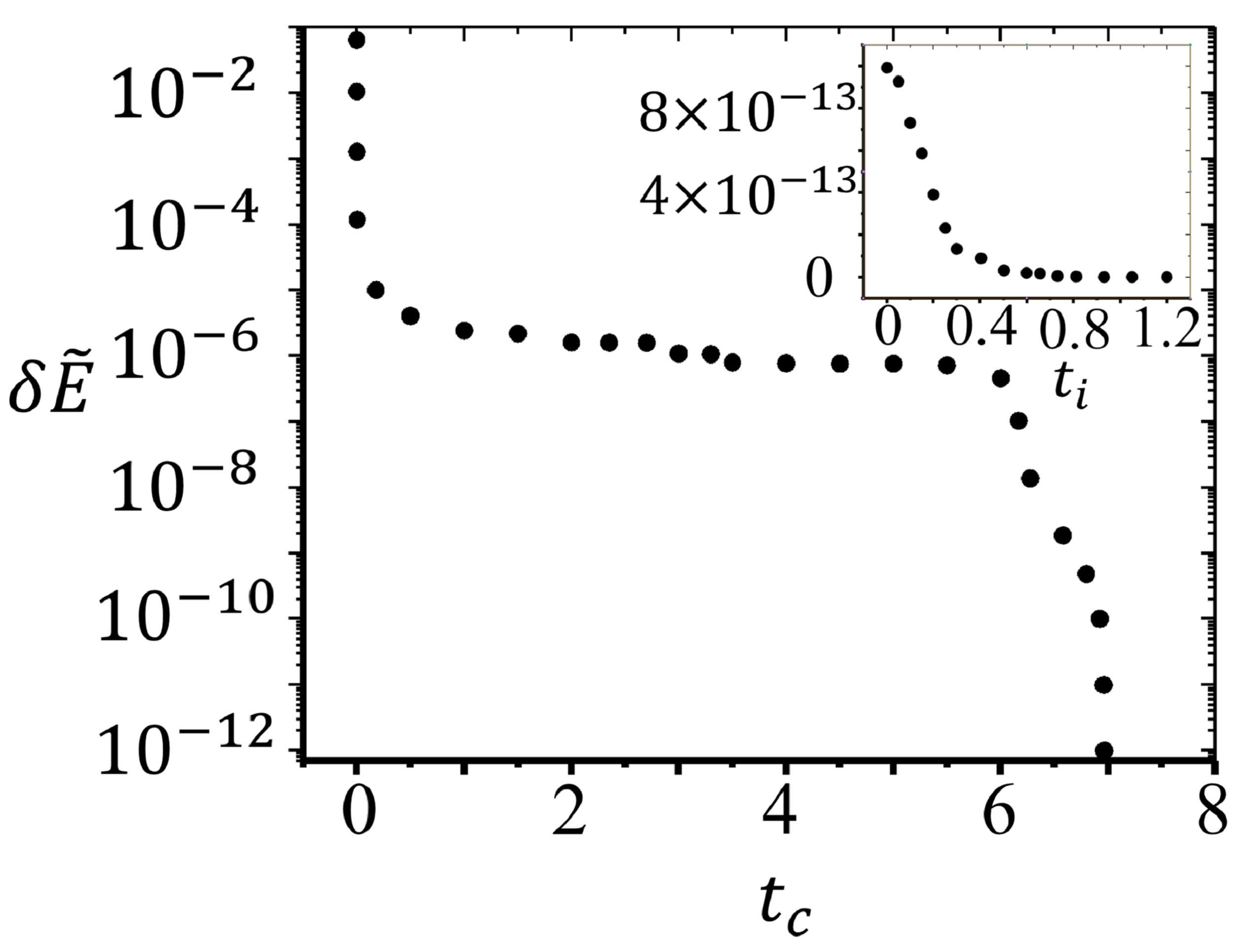
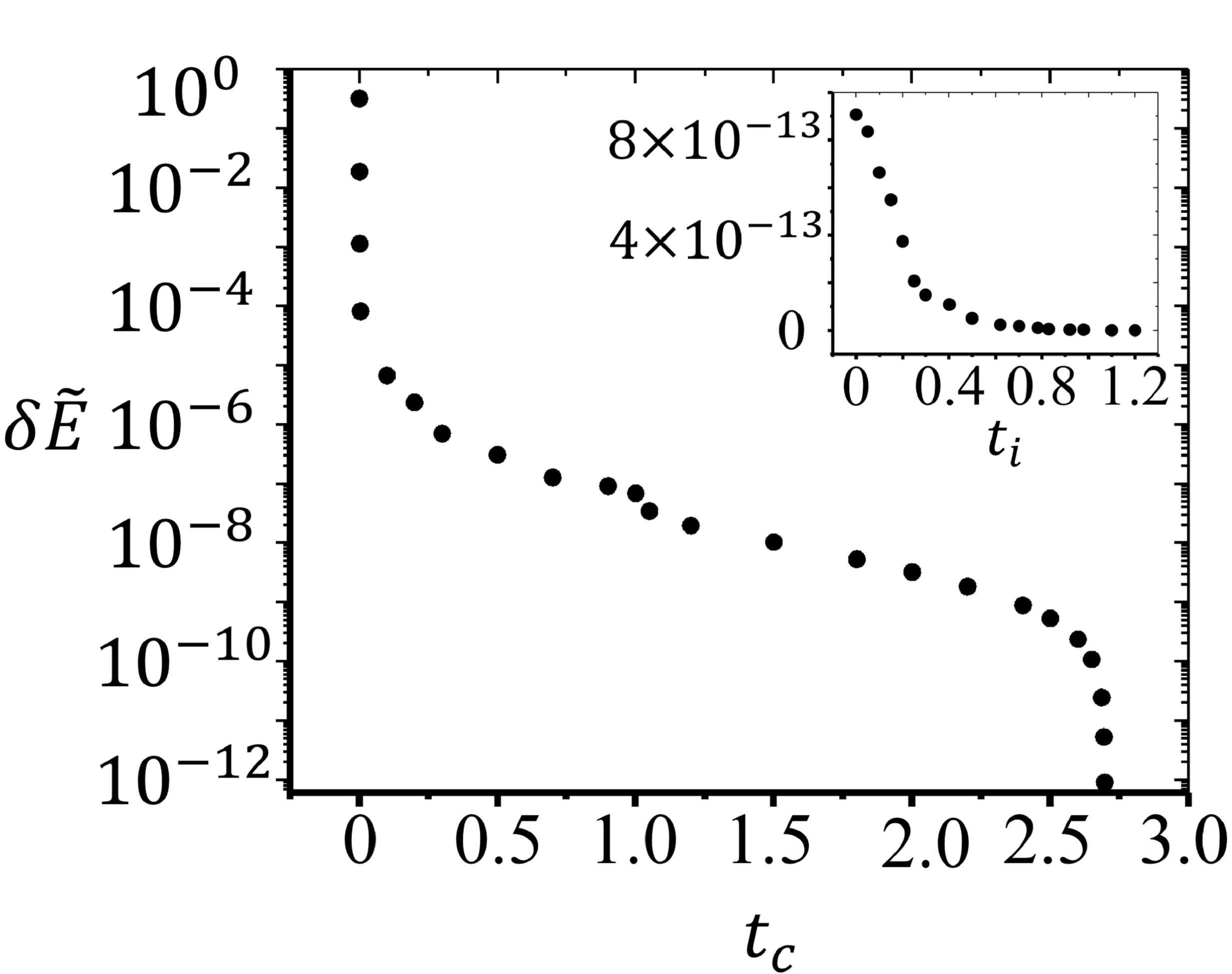
In Fig. 2(a) and 2(b), we show the reduction of system energy towards the lowest value for the cases of and , respectively. , where is the total electrostatic energy and is that in the lowest energy state. The unit of is 10000 sweeps over all the particles. In the collective movement of particles, we gradually reduce the step size from to for efficiency in energy reduction. is the lattice spacing. We further reduce system energy by moving particles individually, and the results are presented in the insets in Fig. 2. We see that the system energy rapidly converges after a few sweeps. Note that the unit of in the individual mode is by sweeping 10000 particles.
We analyze the crystallographic defects in the resulting lowest-energy states using the method of Delaunay triangulation Nelson (2002). While this is a standard procedure of triangulation on plane, the existence and uniqueness of triangulated state using this method on a negatively curved surface is not guaranteed. To solve this problem, we choose a disk-shape neighborhood of each particle, and project it on to the tangent plane. As long as the disk radius is sufficiently small, the curvature within the disk can be ignored. By performing the standard Delaunay triangulation over these particles projected to the plane, we can determine the coordination number of each particle without unambiguity.
To check the validity of our simulation codes, we first simulate the evolution of charged particles on an unperturbed spherical substrate. Starting from an initial state with dense distribution of disclinations, we numerically observe the annihilation of disclinations. Only a few scattered scars and dislocations survive in the final lowest-energy states that our simulations can reach. These observations are consistent with the known results in spherical crystals, suggesting the reliability of our simulations.
III Results and Discussion
III.1 From elongated scars to pleats
Past experimental Bausch et al. (2003) and theoretical Bowick et al. (2002) studies have established that the charges confined on a sphere will spontaneously organize into a triangular lattice, with various sorts of defects Nelson (2002); Bowick and Giomi (2009); Koning and Vitelli (2016), including disclinations, dislocations and scars. A z-fold vertex, i.e. a particle with coordination number , is called a disclination if differs from six. The topological charge of a disinclination is defined as . According to Euler’s theorem Struik (1988), the total topological charge of a spherical crystal is a topological invariant: , where the sum is over all particles of lattice. A dislocation is a pair of five- and seven-fold disclinations, with vanishing net topological charge. A scar is a string of alternating five- and seven-fold disclinations with two five-fold disclinations at the ends. The topological charge of a scar is hence , the same as a single five-fold disclination. A scar is essentially a grain boundary across which a mismatch of crystallographic orientation occurs.
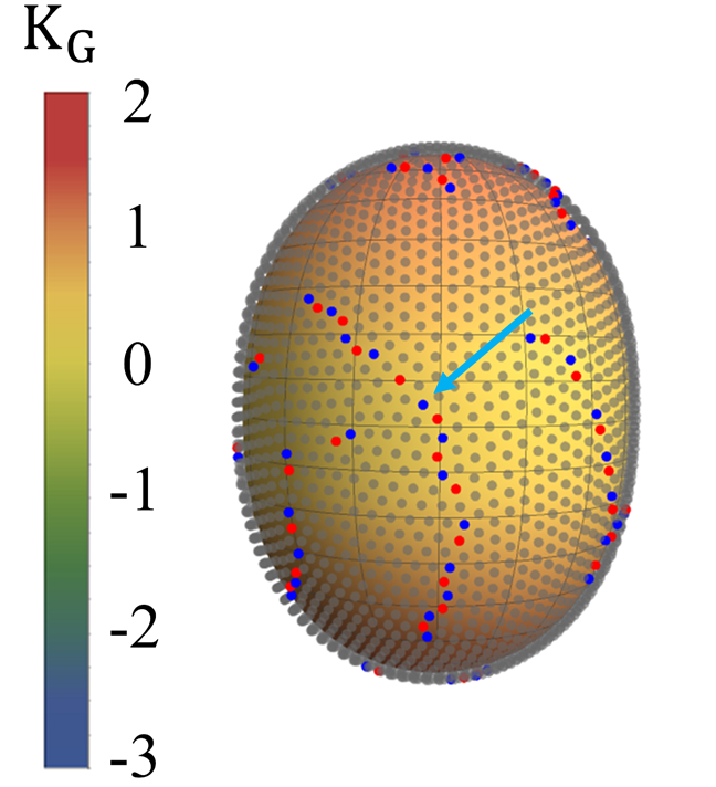
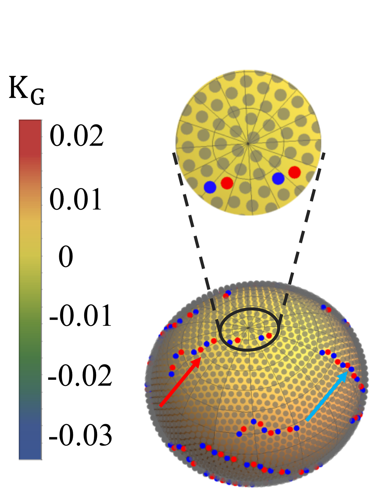
It has been established by previous studies that in a sufficiently large spherical crystal, the isolated point-like five-fold disclinations become unstable and crack into scars Bausch et al. (2003). The length of the scars is determined by the ratio , where is the spherical radius, while is the lattice spacing. By slightly pinching the sphere along its equator, we observe an appreciable change of scar lengths. Elongated scars are found over the pinched spherical crystal, as indicated by the blue arrow in Fig. 1(a). These scars tend to align along the long axis (defined as the z-axis) of the pinched sphere.
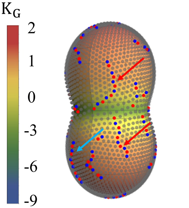
When increases to about , we find strings of alternating disclinations with a five-fold disclination at one end and a seven-fold disinclination at the other end, as indicated by the red arrows in Fig. 1(b). Such defect strings are called pleats. Their net topological charge is zero Irvine et al. (2010). Pleats have been first observed in the crystalline order on negatively curved capillary bridges Irvine et al. (2010). We notice that the negatively charged ends of the pleats, indicated by the red arrows in Fig. 1(b), are anchored at the negatively curved waist, while the positively charged end are located in the positively curved region. Tracking the evolution of defect patterns as we tune the pinching, we find that these two pleats were split out from the same elongated scar. As a consequence of this splitting, the scar becomes significantly shorter. In this process, an extra short scar is emitted to the surrounding crystalline region to conserve the total topological charge.
Past studies have demonstrated that Gaussian curvature can be understood as uniform counter-charge background that screens the topological charges of disclinations Nelson (2002). From this perspective, it is useful to define the geometric charge of the waist area as the integral of the Gaussian curvature, the excess charge as , where is the total disclination charge. Figure 1(e) shows that the excess charge is always positive over the range of , indicating that geometric curvature can only partially screen the topological defects. Furthermore, from Fig. 1(e), we see that surges abruptly as increases from 0.3 to 0.4, which coincides with the emergence of pleats and complete disruption of crystalline order near the waist, as shown in Figs. 1(b) and 1(c). Previous studies have shown that long-range repulsion driven particle-density gradient will induce a negative Gaussian curvature and promote emergence of seven-fold disclinations Nelson (2002); Mughal and Moore (2007). This effect may partially explain the excess topological charges in the waist area.
III.2 Depletion zone structure
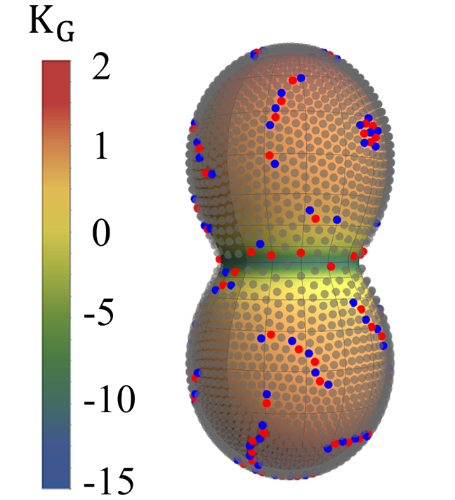
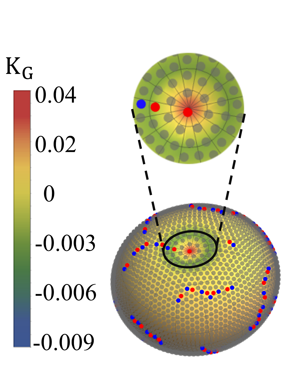
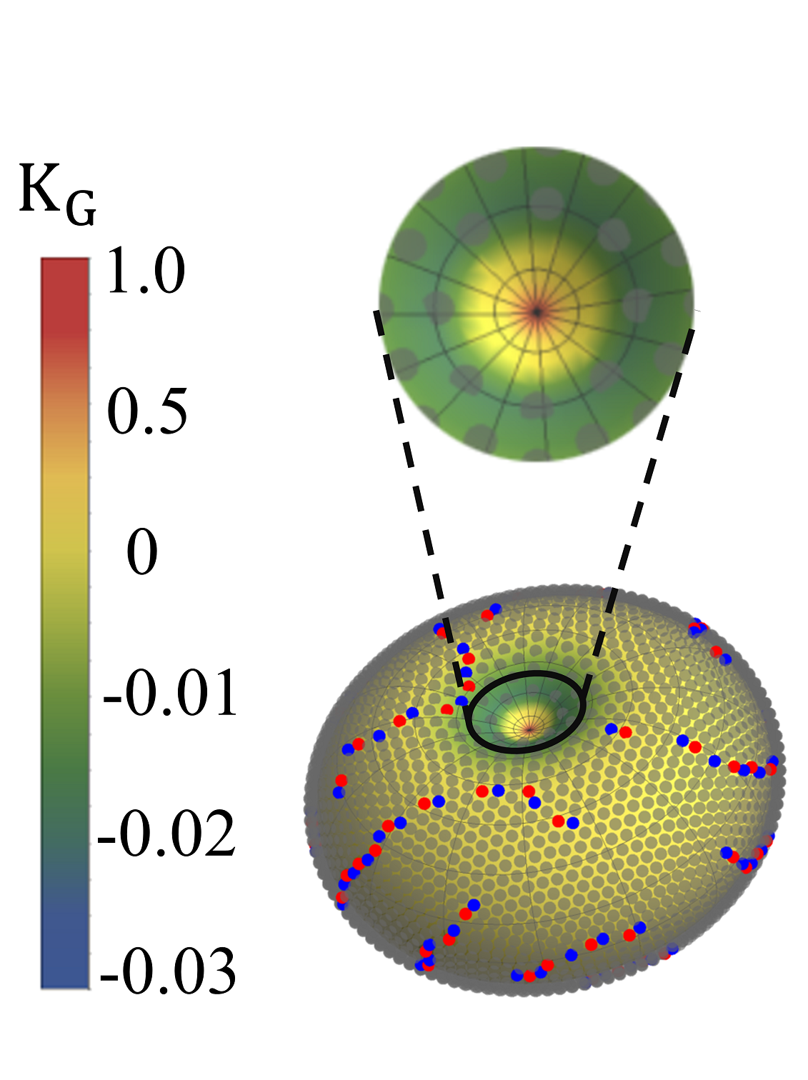
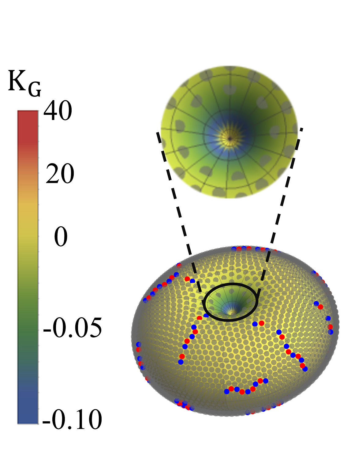
Further increasing to , we observe filling of seven-fold disclinations and complete disruption of the crystalline order near the waist, as illustrated in Fig. 1(c). Concomitantly, the particle density near the waist also becomes much lower: this seems a favorable strategy to lower the electrostatic energy of the system. For , we find the emergence of a sharply defined depletion zone (with no particle) around the waist, as shown in Fig. 1(d).
We shall verify that the depletion zone is a robust feature of the ground state. To this end, we start from initial states where only half of the pinched sphere () is occupied by randomly distributed particles. Once the dynamics is turned on, we find particles migrate to the other side through the waist. In the final lowest-energy state, a depletion zone is formed again over the waist region. The particle numbers at two sides of the waist differ by less than . This indicates that the depletion zone is indeed a robust feature of the ground sate and is independent of the initial condition.
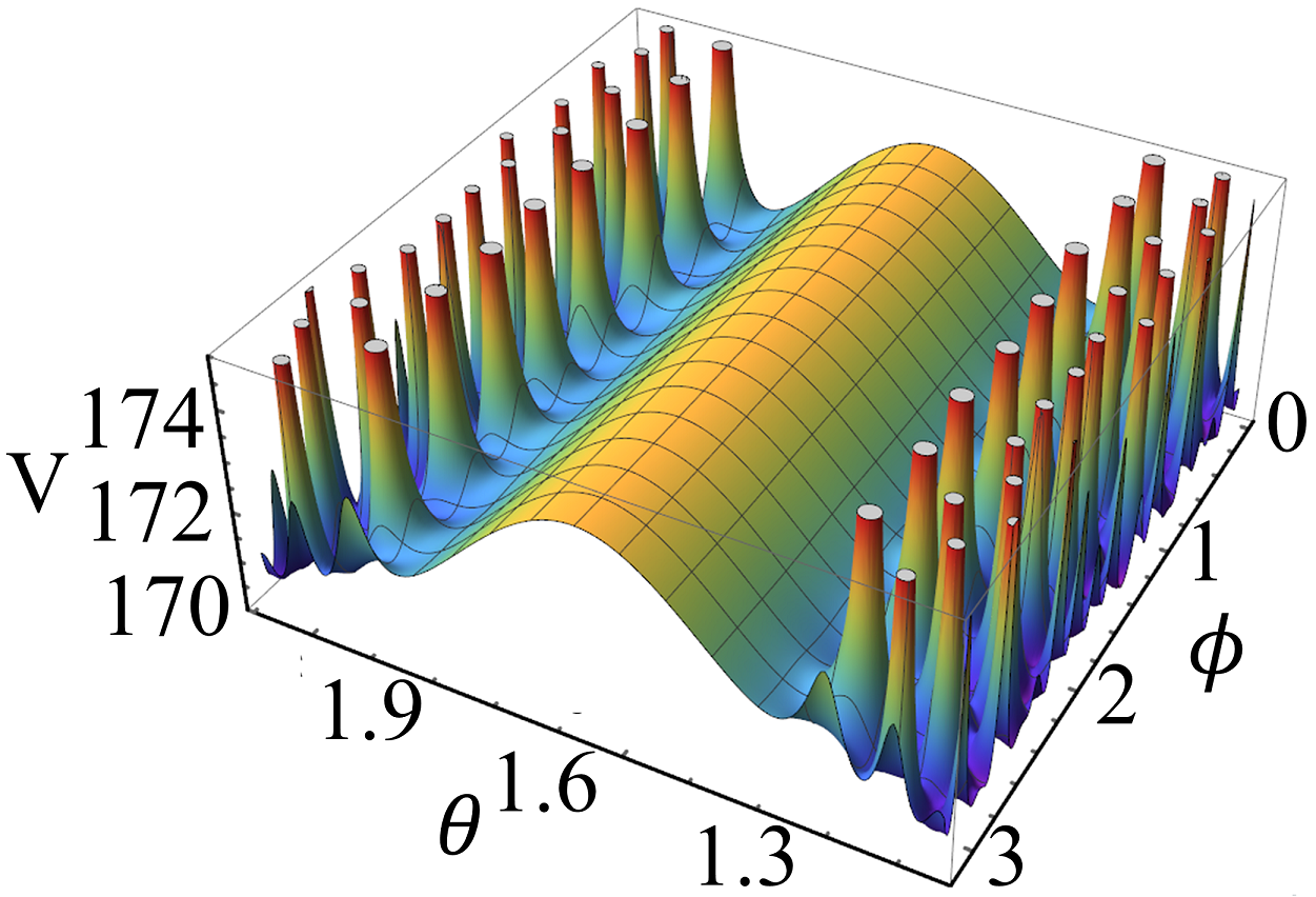
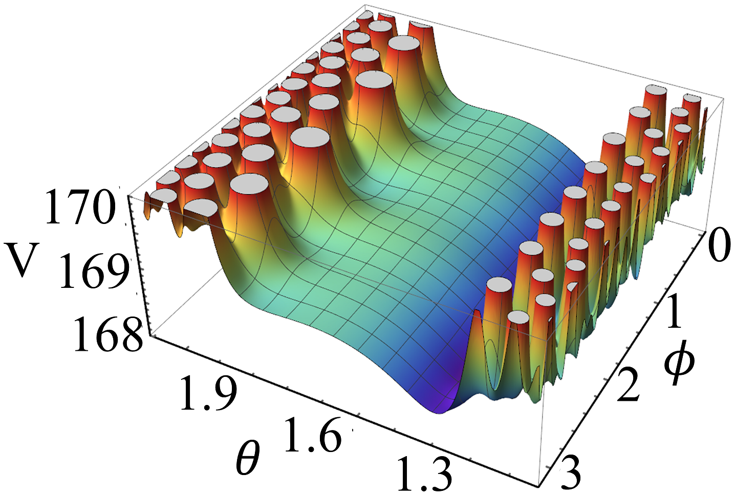
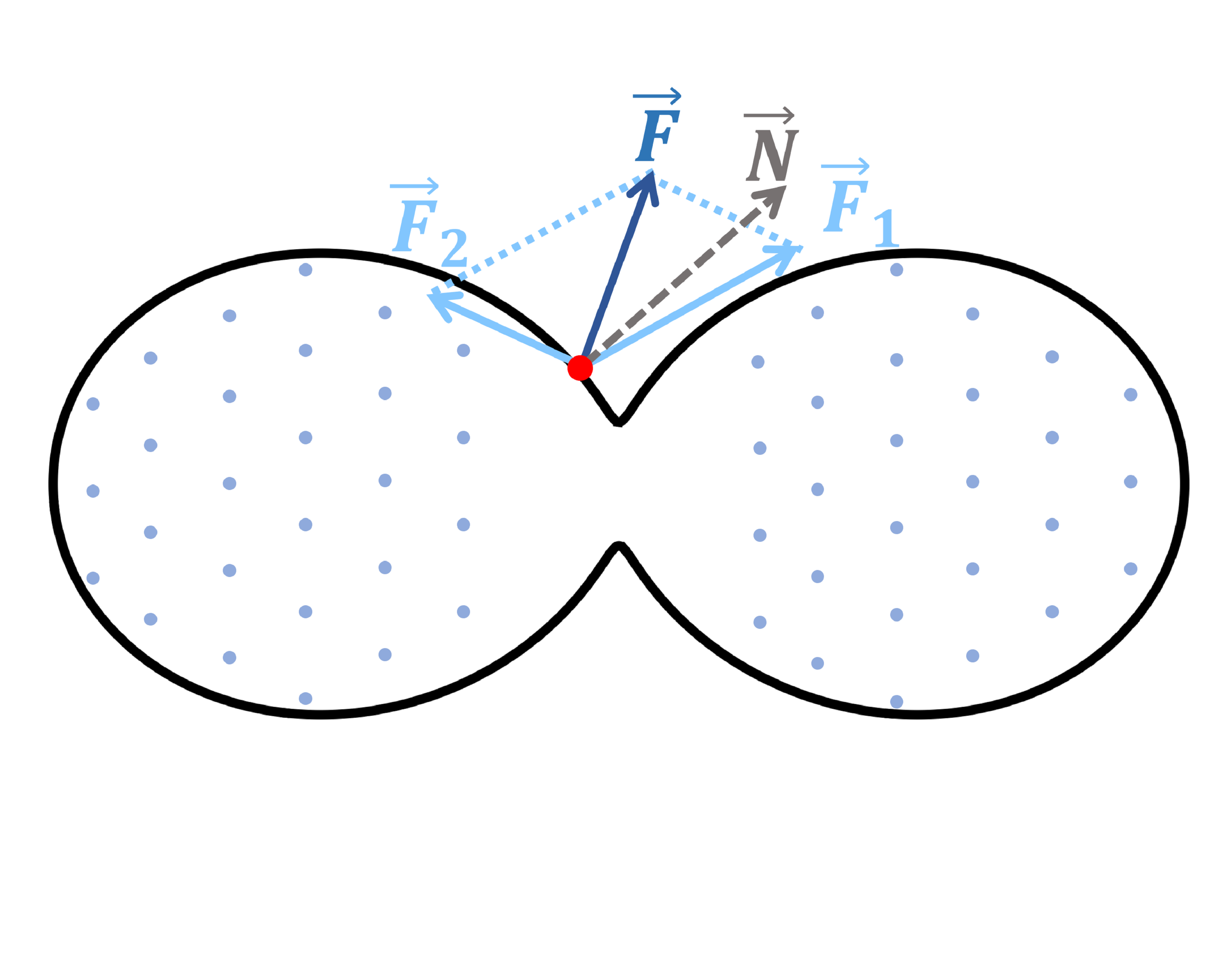
We can also plot the electrostatic potential on the surface as a function of polar and azimuthal angle . Figure 3(a) shows the case where particle numbers in the two sides of the waist are equal. It clearly shows that the potential has a maximum on the waist where . A test charge (recall that all particles are positively charged) cannot be stabilized at the waist: it will move to either side. By contrast, Fig. 3(b) shows the case where particle numbers in two sides are slightly different (992 vs 1008 particles), and there is no potential maximum at the waist. The potential increases monotonically with the polar angle . A test charge placed near the waist will move to the side with lower potential. These analyses further substantiate that the depletion zone is indeed a robust property of the ground state.
To better understand the potential maximum on the waist as shown in Fig. 3(a), let us consider the electrostatic force acting on a test charge slightly to the left of the waist, as schematically shown in Fig. 3(c). Since the test charge is confined on the surface, only the tangent component of the total force is relevant. Now, as the parameter increases, the waist becomes thinner, and the local normal vector rotates to the right. For sufficiently thin waist, is always to the right of , and hence the tangent component of always points to the left. That is, the test charge is pushed to the left. This is exactly what we see in Fig. 3(a). The depletion zone is caused by the local concave geometry near the waist.
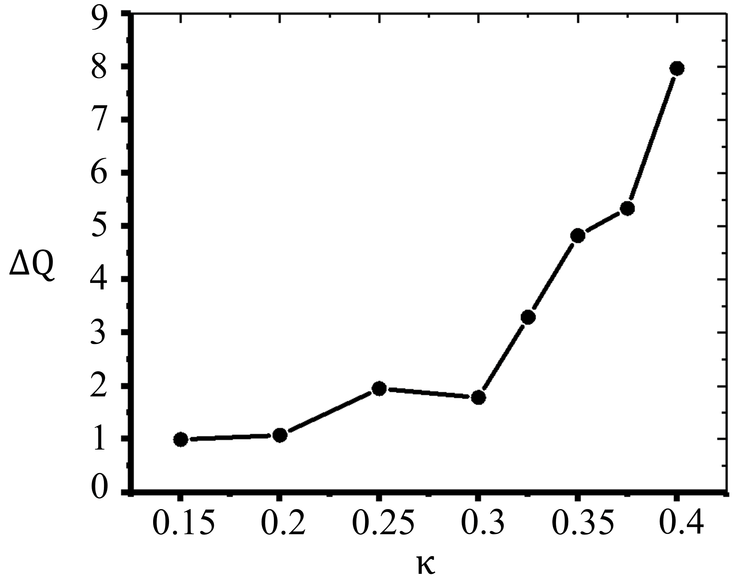
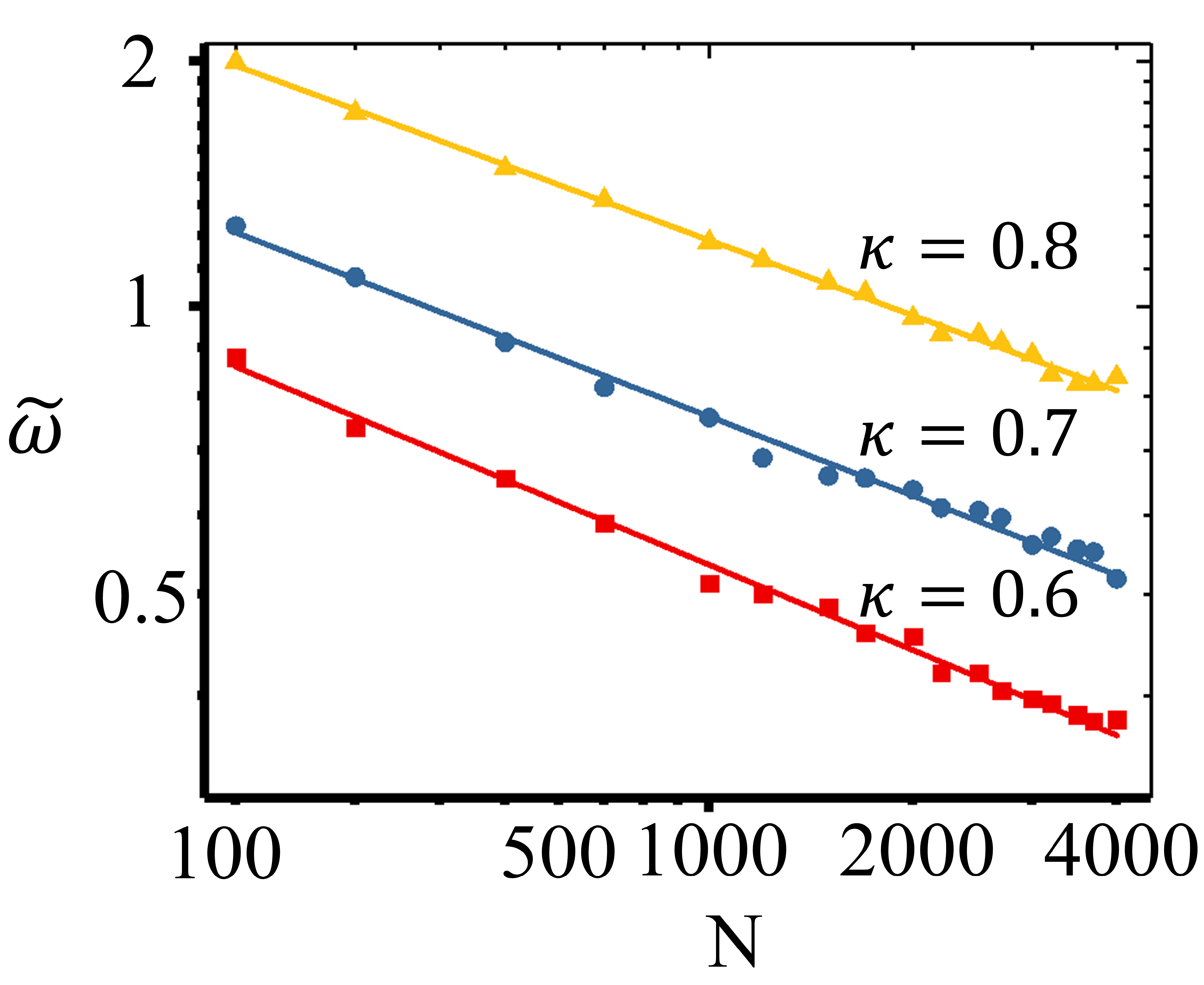
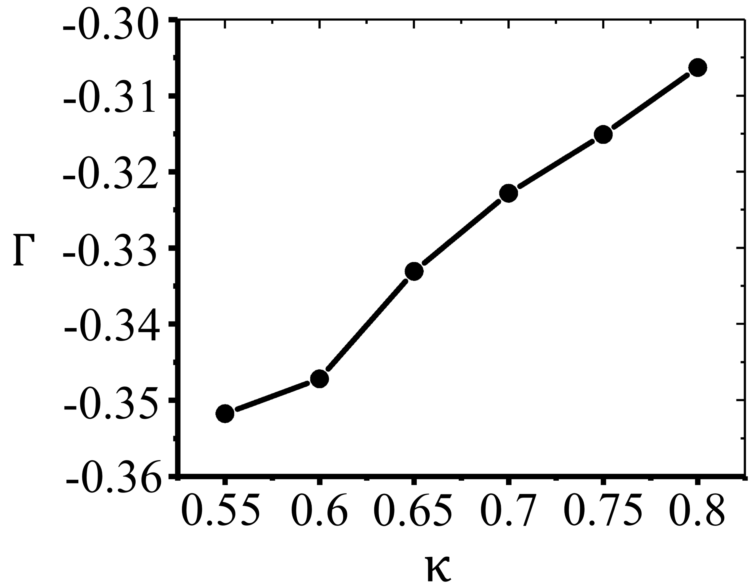
We proceed to discuss the influence of particle number and pinching parameter on the size of the depletion zone. Let be the width of depletion zone normalized by the diameter of waist circle. Figure 4(a) shows that shrinks as increases, with the dependence well-described by a power law for from 100 to 4000:
| (5) |
where the exponent increases linearly with , as shown in Fig. 4(b). This suggests that the depletion zone is a finite size effect, and will eventually disappear in the limit . Indeed, in this limit, we expect that the electrostatic potential is described by Laplace equation with conductor boundary condition, i.e., the potential is constant on the entire surface, since all charges are mobile in our model. Now if the charge density vanishes in certain region on the surface, then both the potential and its normal derivative are fixed. This corresponds to Cauchy boundary conditions, which is known to be incompatible with Laplace equation. We further note that since , decays with slower than the mean inter-particle distance , which scales as .
III.3 Negatively pinched sphere
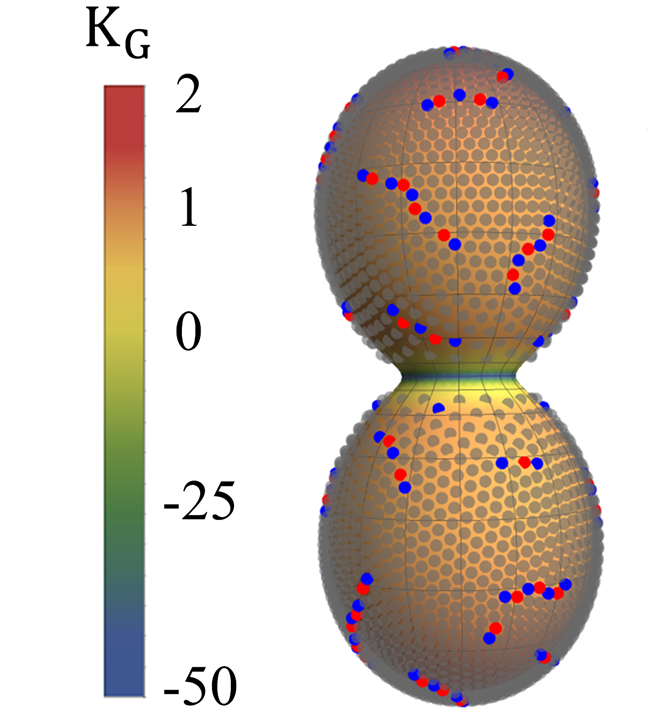
It is also interesting to study the case of negative , where the surface has the shape of biconcave discoid. The defect structures for several negative values of are presented in Fig. 5. At , we find scars [indicated by the blue arrow in Fig. 5(a)] around the rim of the pinched sphere where the Gaussian curvature reaches maximum, and pleats (indicated by the red arrow) over the slightly curved areas. At , we find isolated seven-fold disclination at the dimple as shown in the inset of Fig. 5(b). Depletion zone starts to appear when is even more negative as shown Figs. 5(c) and 5(d) for the cases of , and . As in the case of positive , these depletion zones are expected to vanish in the limit .
III.4 Energetics analysis
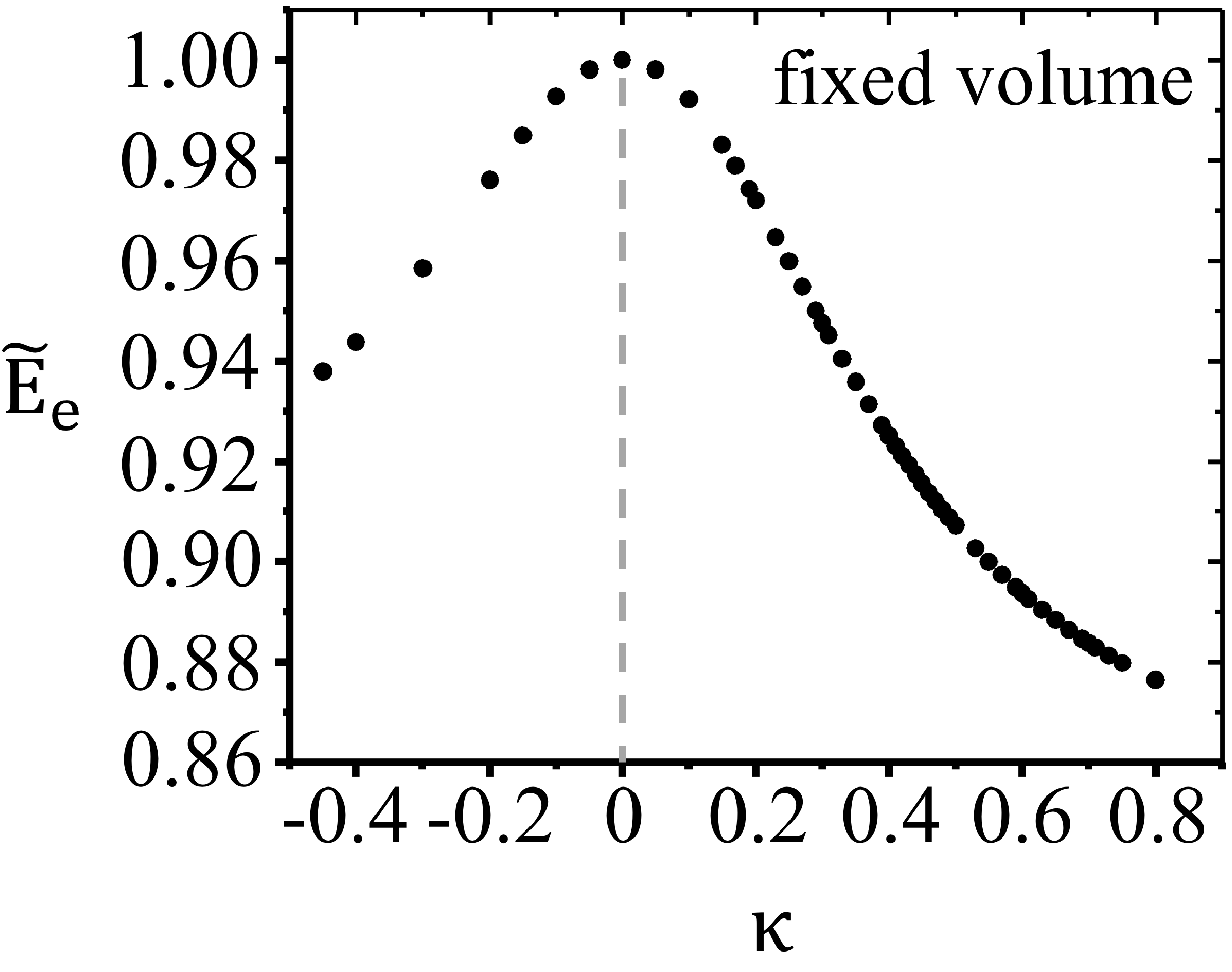
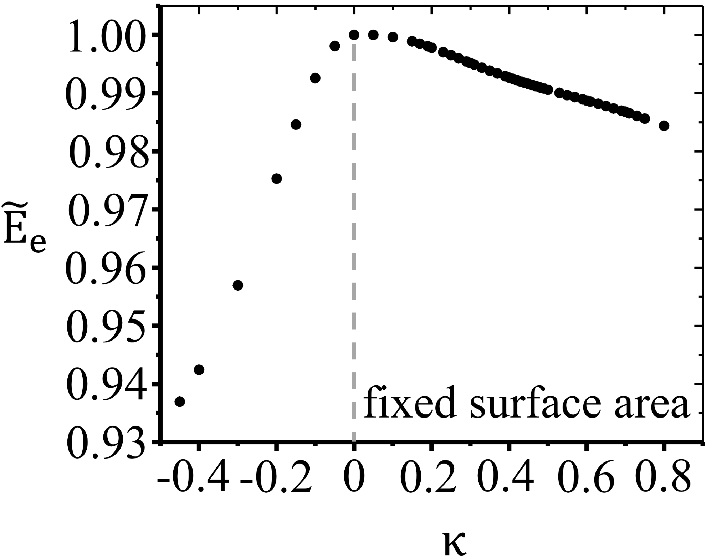
So far, we have studied the packing of charged particles on frozen geometries. Many surfaces in realistic systems are deformable. Here, we track the variation of the total electrostatic energy as a function of the pinching parameter , following two protocols: (1) fixed volume [see Fig. 6(a)] and (2) fixed surface area [see Fig. 6(b)]. For both protocols, the total electrostatic energy decreases monotonously as deviate from zero. This indicates, rather interestingly, that the surface will spontaneously deform to a non-spherical shape as long as the non-electrostatic interactions, such as surface tension and curvature energy, are sufficiently weak. This shall be discussed in a separate work. We also note that the reduction of the total electrostatic energy indicates that pinching a charged sphere can increase its capacitance as an electric conductor, since , where is the total charge, is the electric potential, and is the electrostatic energy of the conductor.
IV CONCLUSION
In this work, the charged interface is deformed in a controllable fashion by tuning the single parameter . This strategy has its merit, but it inevitably excludes the possibilities of other lowest-energy shapes. Rich structures can be developed on a charged interface, such as the experimentally observed singularity structures developed at the poles of a charged ellipsoidal droplet Gomez and Tang (1994); Duft et al. (2003), and the hierarchical bucklings of an elastic charged ribbon Yao and Olvera de la Cruz (2016). Furthermore, fluctuations of surface charges in real systems may modify the bending rigidity and influence the stability of the charged membranes Lau and Pincus (1998); Kim and Sung (2002, 2003). It is of great interest to generalize our model by including these effects to approach a real charged, deformable interface in the future work.
In summary, through the generalized Thomson problem, we study the combined effects of long-range interaction and curvature in shaping the crystalline order on the deformed sphere. As a key result in this work, we discover the depletion zone structure, and reveal its physical origin as a finite size effect that results from the geometry-regulated long-range interaction. These findings provide further insights into the crystallography of charged particles on curved surfaces. A future direction is to fully explore the shape space of a charged interface of various topologies. Notably, singularity structures may be developed over a freely evolving charged interface under the long-range interaction Gomez and Tang (1994); Duft et al. (2003).
Acknowledgement
Z.Y. and J.C. acknowledge support from NSFC Grant No.16Z103010253, the SJTU startup fund under Grant No.WF220441904, and the award of the Chinese Thousand Talents Program for Distinguished Young Scholars under Grants No.16Z127060004 and No. 17Z127060032. X.X. acknowledges support from NSFC via Grant No. 11674217, as well as Shanghai Municipal Education Commission and Shanghai Education Development Foundation via the “Shu Guang” project.
References
- Rayleigh (1882) L. Rayleigh, Philos. Mag. 14, 184 (1882).
- Duft et al. (2002) D. Duft, H. Lebius, B. Huber, C. Guet, and T. Leisner, Phys. Rev. Lett. 89, 084503 (2002).
- Liu et al. (2015) Z. Liu, H. M. Wyss, A. Fernandez-Nieves, and H. C. Shum, Phys. Fluids 27, 082003 (2015).
- Huebner and Chu (1971) A. Huebner and H. Chu, J. Fliud Mech. 49, 361 (1971).
- Guerrero et al. (2014) J. Guerrero, J. Rivero, V. R. Gundabala, M. Perez-Saborid, and A. Fernandez-Nieves, P. Natl. Acad. Sci. U.S.A. 111, 13763 (2014).
- Pairam and Fernández-Nieves (2009) E. Pairam and A. Fernández-Nieves, Phys. Rev. Lett. 102, 234501 (2009).
- Fragkopoulos and Fernández-Nieves (2017) A. A. Fragkopoulos and A. Fernández-Nieves, Phys. Rev. E 95, 033122 (2017).
- Aggeli et al. (2001) A. Aggeli, I. A. Nyrkova, M. Bell, R. Harding, L. Carrick, T. C. McLeish, A. N. Semenov, and N. Boden, P. Natl. Acad. Sci. U.S.A. 98, 11857 (2001).
- Weingarten et al. (2014) A. S. Weingarten, R. V. Kazantsev, L. C. Palmer, M. McClendon, A. R. Koltonow, A. P. Samuel, D. J. Kiebala, M. R. Wasielewski, and S. I. Stupp, Nat. Chem. 6, 964 (2014).
- Andelman (1995) D. Andelman, Handb. Biol. Phys. 1, 603 (1995).
- Lipowsky and Sackmann (1995) R. Lipowsky and E. Sackmann, Structure and Dynamics of Membranes, vol. 1 (Elsevier, 1995).
- Genet et al. (2001) S. Genet, R. Costalat, and J. Burger, Biophys. J. 81, 2442 (2001).
- Kim and Sung (2003) Y. W. Kim and W. Sung, Phys. Rev. Lett. 91, 118101 (2003).
- Vernizzi and Olvera de la Cruz (2007) G. Vernizzi and M. Olvera de la Cruz, P. Natl. Acad. Sci. U.S.A. 104, 18382 (2007).
- Adamcik et al. (2010) J. Adamcik, J.-M. Jung, J. Flakowski, P. De Los Rios, G. Dietler, and R. Mezzenga, Nat. Nanotechnol. 5, 423 (2010).
- Yao and Olvera de la Cruz (2016) Z. Yao and M. Olvera de la Cruz, Phys. Rev. Lett. 116, 148101 (2016).
- Winterhalter and Helfrich (1988) M. Winterhalter and W. Helfrich, J. Phys. Chem. 92, 6865 (1988).
- Lau and Pincus (1998) A. Lau and P. Pincus, Phys. Rev. Lett. 81, 1338 (1998).
- Nguyen et al. (1999) T. Nguyen, I. Rouzina, and B. Shklovskii, Phys. Rev. E 60, 7032 (1999).
- Netz (2001) R. R. Netz, Phys. Rev. E 64, 051401 (2001).
- Palmer et al. (2007) L. C. Palmer, Y. S. Velichko, M. Olvera de La Cruz, and S. I. Stupp, Philos. T. Roy. Soc. A 365, 1417 (2007).
- Moyer et al. (2012) T. J. Moyer, H. Cui, and S. I. Stupp, J. Phys. Chem. B 117, 4604 (2012).
- Taylor (1964) G. Taylor, Proc. R. Soc. London, Ser. A 280, 383 (1964).
- Ziabicki (1976) A. Ziabicki, Fundamentals of Fibre Formation: The Science of Fibre Spinning and Drawing (John Wiley & Sons, New York, 1976).
- Bailey (1988) A. G. Bailey, Electrostatic Spraying of Liquids (John Wiley & Sons, New York, 1988).
- Gomez and Tang (1994) A. Gomez and K. Tang, Phys. Fluids 6, 404 (1994).
- Urbanski et al. (2017) M. Urbanski, C. G. Reyes, J. Noh, A. Sharma, Y. Geng, V. S. R. Jampani, and J. P. Lagerwall, J. Phys.-Condens. Mat. 29, 133003 (2017).
- Thomson (1904) J. J. Thomson, Philos. Mag. 7, 237 (1904).
- Nelson (2002) D. R. Nelson, Defects and Geometry in Condensed Matter Physics (Cambridge University Press, Cambridge, England, 2002).
- De Luca et al. (2005) J. De Luca, S. B. Rodrigues, and Y. Levin, Europhys. Lett. 71, 84 (2005).
- Bowick and Giomi (2009) M. J. Bowick and L. Giomi, Adv. Phys. 58, 449 (2009).
- Koning and Vitelli (2016) V. Koning and V. Vitelli, Crystals and Liquid Crystals Confined to Curved Geometries (John Wiley & Sons, Hoboken, 2016).
- Bausch et al. (2003) A. Bausch, M. Bowick, A. Cacciuto, A. Dinsmore, M. Hsu, D. Nelson, M. Nikolaides, A. Travesset, and D. Weitz, Science 299, 1716 (2003).
- Meng et al. (2014) G. Meng, J. Paulose, D. R. Nelson, and V. N. Manoharan, Science 343, 634 (2014).
- Yao (2017) Z. Yao, Soft Matter 13, 5905 (2017).
- Altschuler et al. (1997) E. L. Altschuler, T. J. Williams, E. R. Ratner, R. Tipton, R. Stong, F. Dowla, and F. Wooten, Phys. Rev. Lett. 78, 2681 (1997).
- Bowick et al. (2002) M. Bowick, A. Cacciuto, D. R. Nelson, and A. Travesset, Phys. Rev. Lett. 89, 185502 (2002).
- Vitelli et al. (2006) V. Vitelli, J. B. Lucks, and D. R. Nelson, Proc. Natl. Acad. Sci. U.S.A. 103, 12323 (2006).
- Burke et al. (2015) C. J. Burke, B. L. Mbanga, Z. Wei, P. T. Spicer, and T. J. Atherton, Soft Matter 11, 5872 (2015).
- Mehta et al. (2016) D. Mehta, J. Chen, D. Z. Chen, H. Kusumaatmaja, and D. J. Wales, Phys. Rev. Lett. 117, 028301 (2016).
- Yao (2016) Z. Yao, Soft Matter 12, 7020 (2016).
- Irvine et al. (2010) W. T. Irvine, V. Vitelli, and P. M. Chaikin, Nature (London) 468, 947 (2010).
- Irvine et al. (2012) W. T. Irvine, M. J. Bowick, and P. M. Chaikin, Nat. Mater. 11, 948 (2012).
- Struik (1988) D. Struik, Lectures on Classical Differential Geometry (Dover Publications, New York, 1988), 2nd ed.
- Greub et al. (1973) W. Greub, S. Halperin, and R. Vanstone, Lie Groups, Principal Bundles, and Characteristic Classes (Academic Press, New York and London, 1973).
- Yao and Olvera de la Cruz (2013) Z. Yao and M. Olvera de la Cruz, Phys. Rev. Lett. 111, 115503 (2013).
- Mughal and Moore (2007) A. Mughal and M. Moore, Phys. Rev. E 76, 011606 (2007).
- Duft et al. (2003) D. Duft, T. Achtzehn, R. Müller, B. A. Huber, and T. Leisner, Nature (London) 421, 128 (2003).
- Kim and Sung (2002) Y. Kim and W. Sung, Europhys. Lett. 58, 147 (2002).