Active Underwater Detection with an Array of Atomic Magnetometers
Abstract
We report on a 22 array of radio-frequency atomic magnetometers in magnetic induction tomography configuration. Active detection, localization, and real-time tracking of conductive, non-magnetic targets are demonstrated in air and saline water. Penetration in different media and detection are achieved thanks to the sensitivity and tunability of the sensors, and to the active nature of magnetic induction probing. We obtained a 100 success rate for automatic detection and 93 success rate for automatic localization in air and water, up to 190 mm away from the sensors’ plane (100 mm underwater). We anticipate magnetic induction tomography with arrays of atomic magnetometers finding applications in civil engineering and maintenance, oil&gas industry, geological surveys, marine science, archeology, search and rescue, and security and surveillance.
pacs:
(280.4788) Optical sensing and sensors; (280.0280) Remote sensing and sensors; (230.3810) Magneto-optic systems; (230.2240) Faraday effect.This is a preprint version of the article appeared in Appl. Opt. 57, 10, 2346-2351 (2018) DOI: 10.1364/AO.57.002346.
I Introduction
Detection, localization, and tracking of remote or concealed objects is an open problem in many fields, in particular when penetration through absorbing or scattering media is required Yenchek et al. (2012); Lord (2017); Lasaponara and Masini (2014); Eismann et al. (2009); Oracevic et al. (2014); Pajares (2015). A critical case is underwater detection, where many conventional detection techniques are often ineffective Gerginov et al. (2017). For example, optical methods can be severely challenged Schettini and Corchs (2010), and acoustic systems incur increased difficulties at shallow depths Bucker (1994); Abraham and Willett (2002). In addition, the use of ionizing radiation or particles is often impractical, or technically impossible because of the interaction (or the lack thereof) with media and targets.
Here, we present a proof-of-concept demonstration of detection and localization with an array of atomic magnetometers (AMs) Budker and Romalis (2007) operating in magnetic induction tomography (MIT) Griffiths (2001) configuration. This new approach does not suffer from the abovementioned limitations, and it is suitable for multi-purpose use. Thanks to the sensitivity and tunability of AMs, MIT can be implemented with low fields and at low frequencies, thus matching the requirements for long range penetration in media. In addition, the room temperature operation of AMs in unshielded environments, low running costs, miniaturization, scalability, and low costs for additional units make them an ideal solution for remote or underwater detection and localization Gerginov et al. (2017).
We demonstrate active and automatic detection, localization, and tracking of conductive non-magnetic targets in air and in saline water, by continuously and simultaneously monitoring the output of a 22 planar array of AMs. We have obtained an overall success rate for detection of 100 in the explored configurations, and 93 successful localization. Real-time tracking of moving targets is also demonstrated, as well as multiple target simultaneous detection.
Although arrays of AMs have been previously realized (see, for example, Knowles et al. (2009); Wyllie et al. (2012); Cooper et al. (2016)), their operation in MIT modality has not. Our results demonstrate the feasibility of MIT with an array of AMs, and the relevance of such an instrument for detection and localization of concealed targets. The technology can also be integrated with remote detection of rotating machinery with AMs Marmugi et al. (2017), to create a multi-function sensing platform. This would provide a compact, safe, and active alternative for remote monitoring, surveying, and surveillance in many fields, as well as for increasing the throughput of MIT-AM imaging systems Deans et al. (2016, 2017a).
II Array of Radio-frequency Atomic Magnetometers
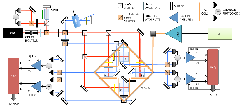
The setup is sketched in Fig. 1. Four radio-frequency (RF) atomic magnetometers (AM) Savukov et al. (2005); Ledbetter et al. (2007); Chalupczak et al. (2012), labelled as Sn, where n=1,…,4, are arranged in a 22 planar configuration. Each sensor relies on Faraday rotation to detect the presence of a conductive target, where eddy currents are induced by an AC magnetic field orthogonal to the sensors’ plane. The output of each sensor (2 channels) is multiplexed in a DAQ board (NI USB-6009) and analyzed in real time via LabVIEW. Automatic control and variable thresholds (i.e. “decision levels”) are included for alarm triggering.
Detection is based on MIT. An AC primary magnetic field induces eddy currents in the target, which in turn generate a secondary field, oscillating at the same frequency. A phase-sensitive detection scheme referenced to the primary field extracts the amplitude of the secondary field and its phase lag . The presence of a target is detected by measuring perturbations to the total magnetic field. This approach is inherently active: it triggers an unavoidable response in the target. The technique does not rely on intrinsic magnetic signatures, and is therefore well-suited for non-magnetic or de-magnetized targets. Furthermore, the electromagnetic near-field nature of the process allows operation also in shallow water, where acoustic-based systems are challenged.
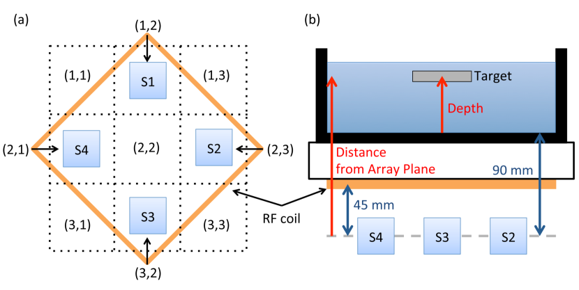
In our setup, the primary field is produced by a square coil (RF coil) of side L=230 mm (15 turns), placed in a parallel plane 45 mm above the sensors’ plane (Fig. 2). The coil is powered by a bipolar amplifier driven by a waveform generator.
The four RF AMs are based on a crossed pump/probe configuration, exciting the D2 line of 87Rb. The atomic vapor is contained in 25 mm cubic quartz cells, with 20 Torr of N2 as buffer gas. A single semiconductor laser source at 780 nm generates four polarized probe beams (1 mW, beam waist 4 mm, 4.6Isat) tuned to the F=2 F′=3 transition. Circular Helmholtz coils (diameter 85 mm) provide a bias field for optical pumping for each Sn.
The MIT primary field acts as an RF drive for orthogonal components of the atomic polarization, by resonantly coupling adjacent Zeeman sub-levels. This sets the atomic spins in precession (Larmor precession) at the frequency of the primary field. Such motion is detected through polarization rotation by four -polarized probe beams (50 W, beam waist 2.5 mm), detuned by +420 MHz with respect to the “pump” transition. Faraday rotation is measured by four independent polarimeters, whose output is selectively amplified by four dual-phase lock-in amplifiers. This allows simultaneous operation of the four sensors.
The secondary field produced by the target causes a change in the polarization rotation and therefore a change in the amplitude rn and in the phase of the n-th sensor’s output. In this way, the 22 array provides 8 streams of data for analysis.
The four sensors are arranged at the vertexes of a square with side 105 mm. This distance and the mutual orientation allowed reduction of cross-talk effects to a negligible value, as well as a satisfactory coverage of the experimental area. Each sensor has a sensitivity of 3 nT/ at 10 kHz, measured with all four sensors in simultaneous operation. The sensors’ performance could be further improved by active compensation of stray magnetic fields Deans et al. (2017a). Unlike previous realizations of MIT with RF AM single sensors Deans et al. (2016); Wickenbrock et al. (2016); Deans et al. (2017a), the targets are not enclosed between the sensor(s) and the RF coil. The entire sensing system lies below (or above) the object of interest. This has major advantages in view of practical applications, from screening Deans et al. (2017a) to biomedical imaging Marmugi and Renzoni (2016), as well as underground and underwater surveying.
III Array Operation: Detection and Localization of Conductive Targets
The penetration of an AC magnetic field in media is governed by the exponential decay , where the skin depth is:
| (1) |
Here, is the AC field’s frequency; is the permittivity; is the permeability; and is the electric conductivity of the medium. According to Eq. 1, low frequencies are required for long range penetration and hence remote detection. In this regime, AMs outperform conventional sensors Savukov et al. (2007); Gerginov et al. (2017). A primary field frequency of between 10 kHz and 20 kHz is chosen for this work. This allows sufficient penetration of the MIT fields in media and targets, with negligible attenuation in air ( S/m Pawar et al. (2009)): penetration exceeding 108 km can be obtained in principle. This range is significantly reduced in sea water, as discussed in Sec. 4.IV.1. We recall that MIT operation of RF AM in a band as low as 102 Hz has been recently reported Deans et al. (2017a). With this choice of frequencies and distances between the sensor array and the target, the electromagnetic interaction is limited to the near-field regime. This corresponds to the quasi-static limit of electromagnetism, described by diffusion equations, rather than to the familiar wave propagation regime of far-field electromagnetism.
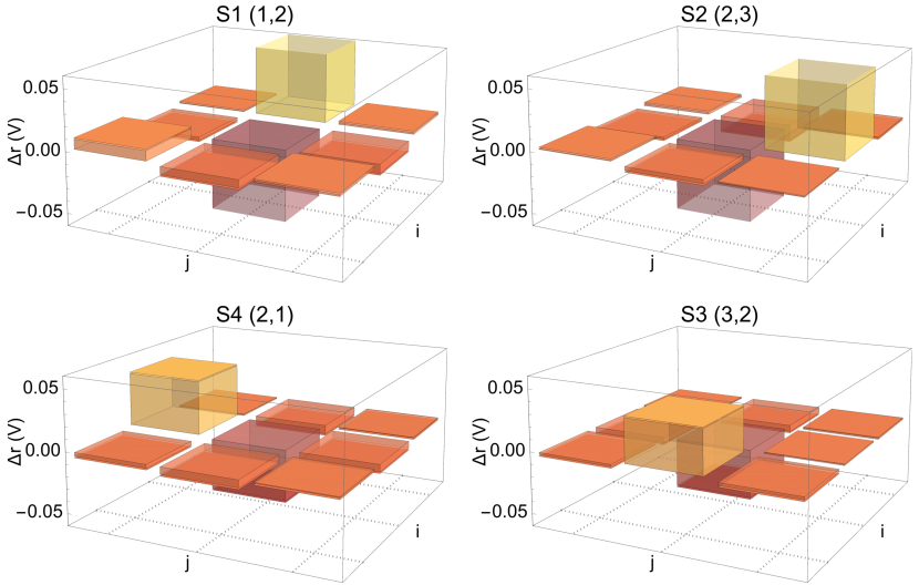
To demonstrate the operation of the array and the limited impact of cross-talk, the response of the four sensors is measured as a function of the target’s position. Figure 3 shows the variation in the amplitude of the four Sn when an Al plate (10511010 mm3) is placed on the nine positions . r=—rtarget-rbg— (where rtarget,bg indicate the amplitude of the Faraday rotation signal with and without the target, respectively) is plotted as a function of target’s position.
A systematic increase of r when the target is in proximity of the sensor is observed. Given the experimental arrangement (Fig. 2(b)), direct screening of the primary field by the target is excluded. This behavior is consistent with MIT detection: the secondary field excited in the target perturbs the RF-driven Faraday rotation in the array. The effect is larger when the target is closer to the sensor, where the secondary field is stronger: up to 10 times larger than the neighboring values. Furthermore, a systematic decrease of the signal from all sensors is observed when the object is in the center of the grid (2,2). This allows unambiguous localization of the target in five different positions. The four vertexes of the coordinate grid are not taken into consideration.
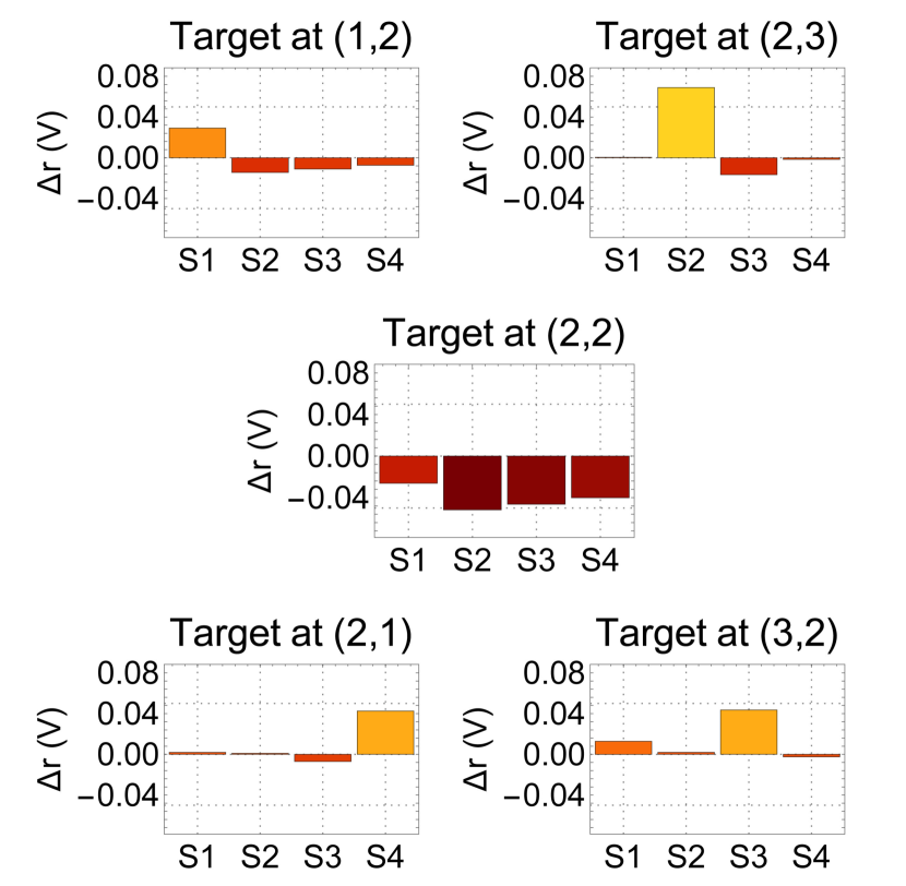
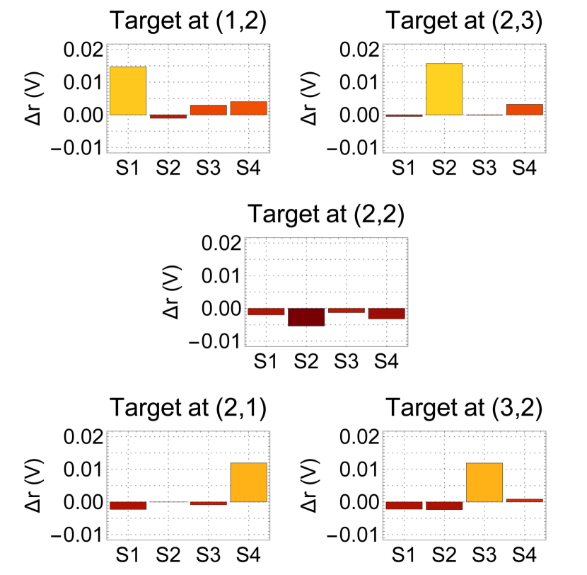
This is demonstrated in Fig. 4. r is simultaneously measured by the four Sn when the Al plate is placed in different positions, 90 mm above the sensors’ plane. The LabVIEW control displays the measured values in real time and compares them to the corresponding background. An alarm showing the target’s position on the grid is automatically triggered upon detection (see also Visualization 1 Deans et al. (2017b)).
Clear signatures of the target’s presence and position are confirmed, with negligible cross-talk among Sn. We attribute the small variations observed in some cases to random fluctuations (10 in the response of the same sensor in the same conditions, over several days, in the case of the smallest tested target sized 445013 mm3). However, these do not hamper the detection and localization of the target: we obtained 100 correct automatic detections and localizations with the Al plate.
The phase variation is also recorded. A decrease is observed when the object is above a sensor, leading to unambiguous detection and correct localization. After detailed analysis, we found to be a less robust parameter than r. We attribute this to the larger intrinsic variability of the phase data. Therefore, is not taken into further consideration in this work.
Figure 5 shows the results of a similar experiment, conducted with an Al block of 445013 mm3 in air, 90 mm above the sensors’ plane. A five-fold decrease of the signal is observed. This is due to the smaller size of the target: the 5 decrease in r is consistent with the ratio of the two targets’ areas, 5.25 foo .
Nevertheless, clear detection and effective localization are demonstrated. Overall, a correct localization rate of 95.2 over 21 sets of tests was obtained at 20 kHz.
IV Underwater Detection and Localization
IV.1 Saline Water Test-Bed
To test the array with underwater detection and localization, we used a test-bed mimicking the worst-case scenario of sea water. A 25 mm thick Perspex platform above the main coil supports a Nylon water tank (355215265 mm3). The target is immersed in the water and held at different depths. The sensors’ plane and the water level are separated by 90 mm containing air and two layers of plastic. This mimics the realistic scenario of a sensing platform above water on a supporting structure and an underwater target.
To reproduce the average electric conductivity of sea water, we used a 0.0231 NaCl solution with de-ionized water. De-ionized water allows detailed control of the solution conductivity. A NaCl/water solution with a salinity of 22.1 matches the sea conditions at 22∘C: F/m, H/m, =3.3 S/m Ellison et al. (1998); Benelli and Pozzebon (2013).
In the band chosen for this work (10 to 20 kHz), skin depth in sea water varies between 2.8 m and 1.9 m. Penetration of km can be achieved by further reducing the RF frequency (Eq. 1).
IV.2 Underwater Experimental Results
In this section, we demonstrate the detection and localization of underwater non-magnetic targets.
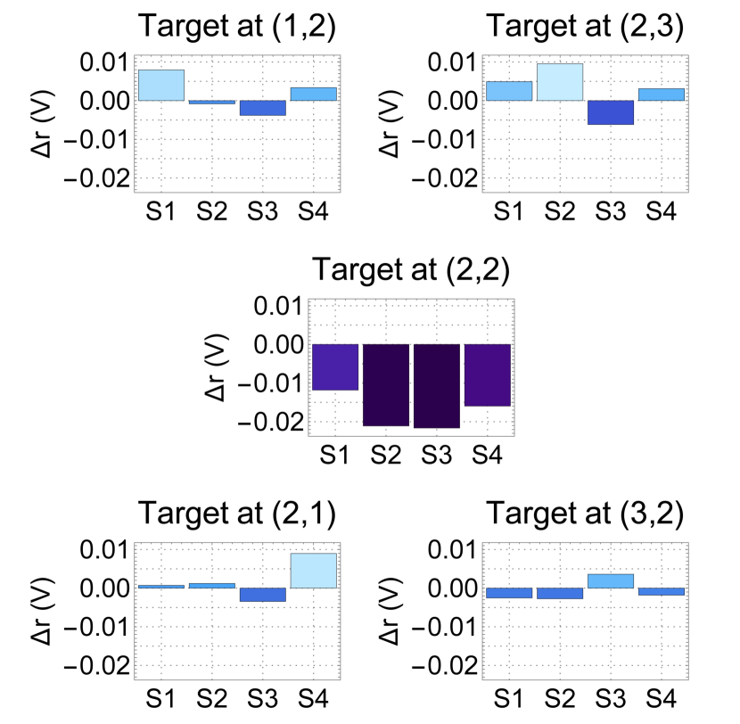
In Fig. 6, the Al plate is placed 30 mm under water, 120 mm above the array’s plane.
The absolute levels of the amplitude signals decrease. In particular, we measured r 8 times smaller than Fig. 4. This value reduces to a factor 3 in the case of the central position. Nevertheless, the array measures consistent variations in presence of the target, and unambiguous detection and localization is achieved.
Overall, excellent success rates for automatic localization are obtained: over 22 separate tests at different depths, the success rate was 91. This number increases to 95 for depths smaller than 50 mm (140 mm above the array plane). At deeper locations, the success rate progressively decreases: at 65 mm deep, automatic localization is successful in 70 of cases. No correlations were found between the position and the failure rate.
Underwater depth and distance from the RF coil play a relevant role, as demonstrated by Fig. 7. In the graph, S2 r is plotted versus the depth underwater and the distance from the sensors’ plane of a thin Al plate (105733 mm3) in position .
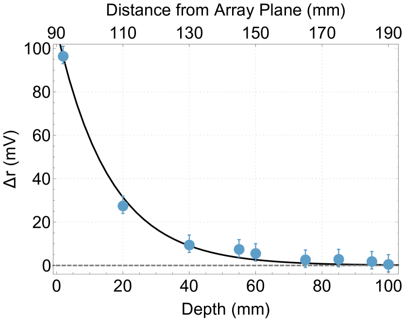
Water attenuates both the primary and the secondary fields, producing a noticeable decrease of the MIT signal. Such variation is estimated of the order of 10. Therefore, water attenuation alone cannot account for the observed decrease in r. These results could be improved by optimizing the design of the RF source, or by using better approaches for automatic localization, such as machine learning Deans et al. (2018). Increasing the number of sensors will also improve the localization and tracking performance. We recall that detection and localization in shallow water - where acoustic methods are overwhelmed by echoes and optical methods are hampered by opacity and turbulence of water - is of primary importance for a number of fields, including surveillance, industrial monitoring, and surveying.
Finally, by using the LabVIEW automatic real-time detection interface, demonstrations of: i) Detection and localization of multiple targets; ii) Suppression of background structures or targets; and iii) Live tracking of moving targets were demonstrated, as shown in Visualization 1 Deans et al. (2017b). These features are essential pre-requisites for the proposed applications, in particular surveillance. The active nature of the MIT approach makes conventional passive countermeasures such as magnetic de-gaussing Kephart et al. (2011), or acoustic cloaking Chen and Chan (2007) ineffective. We also note that, given the broad tunability of AMs, the primary field source frequency can be easily tuned for achieving different penetrations, as well as avoiding noisy bands, or concealing the active probing.
V Conclusions
We have demonstrated detection and localization of conductive, non-magnetic targets by using a 22, planar array of radio-frequency atomic magnetometers operating in magnetic induction tomography configuration. The sensors in the array are operated continuously and simultaneously with negligible cross-talk. The active nature of the magnetic induction detection, combined with the sensitivity and tunability of RF AMs, make this approach suitable for operation in unshielded environments, and achieving long penetration ranges, to detect fixed and moving targets.
A proof-of-concept demonstration in saline water proved the feasibility of an MIT-based array of AMs for underwater detection and tracking, also in shallow water where other conventional approaches have limited effectiveness.
Our results lay the grounds for potential applications from archeological surveys to civil engineering. We found no evidence to suggest fundamental limitations in scaling up the array or increasing the monitored area. Furthermore, integrating the active tracking demonstrated here with passive detection of the AC electromagnetic signatures of motors Marmugi et al. (2017) could provide a novel class of early surveillance platforms, suitable for land, air, and water applications.
UK Quantum Technology Hub in Sensing and Metrology, Engineering and Physical Sciences Research Council (EPSRC) (EP/M013294/1). Engineering and Physical Sciences Research Council (EPSRC) (EP/L015242/1).
Cameron Deans acknowledges support by the EPSRC.
References
- Yenchek et al. (2012) M. R. Yenchek, G. T. Homce, N. W. Damiano, and J. R. Srednicki, IEEE Transactions on Industry Applications 48, 1700 (2012).
- Lord (2017) B. Lord, The Leading Edge 36, 24 (2017), https://doi.org/10.1190/tle36010024.1 .
- Lasaponara and Masini (2014) R. Lasaponara and N. Masini, Satellite Remote Sensing: A New Tool for Archaeology-Volume 16 (Springer Publishing Company, Incorporated, 2014).
- Eismann et al. (2009) M. T. Eismann, A. D. Stocker, and N. M. Nasrabadi, Proceedings of the IEEE 97, 1031 (2009).
-
Oracevic et al. (2014)
A. Oracevic, S. Akba?,
S. Ozdemir, and M. Kos, in 2014
International Conference on Anti-Counterfeiting, Sec-
urity and Identification (ASID) (2014) pp. 1–5. -
Pajares (2015)
G. Pajares, Photogrammetric Engineering &
Remote
Sensing 81, 281 (2015). - Gerginov et al. (2017) V. Gerginov, F. C. S. da Silva, and D. Howe, Review of Scientific Instruments 88, 125005 (2017).
-
Schettini and Corchs (2010)
R. Schettini and S. Corchs, EURASIP Journal on Adv-
ances in Signal Processing 2010, 746052 (2010). -
Bucker (1994)
H. Bucker, The Journal of the Acousti-
cal Society of America 96, 3809 (1994), https://doi.org/10.1121/1.410571 . - Abraham and Willett (2002) D. A. Abraham and P. K. Willett, IEEE Journal of Oceanic Engineering 27, 35 (2002).
- Budker and Romalis (2007) D. Budker and M. Romalis, Nature Physics 3, 227 EP (2007).
- Griffiths (2001) H. Griffiths, Measurement Science and Technology 12, 1126 (2001).
-
Knowles et al. (2009)
P. Knowles, G. Bison,
N. Castagna, A. Hofer, A. Mtchedlishvili, A. Pazgalev, and A. Weis, Nuclear Instruments and Methods in Physics Research Section
A: Accelerators, Spectrometers, Detectors and Associated Equipment 611, 306 (2009), particle Physics with Slow Neutrons. - Wyllie et al. (2012) R. Wyllie, M. Kauer, R. T. Wakai, and T. G. Walker, Opt. Lett. 37, 2247 (2012).
- Cooper et al. (2016) R. J. Cooper, D. W. Prescott, P. Matz, K. L. Sauer, N. Dural, M. V. Romalis, E. L. Foley, T. W. Kornack, M. Monti, and J. Okamitsu, Phys. Rev. Applied 6, 064014 (2016).
- Marmugi et al. (2017) L. Marmugi, L. Gori, S. Hussain, C. Deans, and F. Renzoni, Appl. Opt. 56, 743 (2017).
- Deans et al. (2016) C. Deans, L. Marmugi, S. Hussain, and F. Renzoni, Applied Physics Letters 108, 103503 (2016).
- Deans et al. (2017a) C. Deans, L. Marmugi, and F. Renzoni, Opt. Express 25, 17911 (2017a).
- Savukov et al. (2005) I. M. Savukov, S. J. Seltzer, M. V. Romalis, and K. L. Sauer, Phys. Rev. Lett. 95, 063004 (2005).
- Ledbetter et al. (2007) M. P. Ledbetter, V. M. Acosta, S. M. Rochester, D. Budker, S. Pustelny, and V. V. Yashchuk, Phys. Rev. A 75, 023405 (2007).
- Chalupczak et al. (2012) W. Chalupczak, R. M. Godun, S. Pustelny, and W. Gawlik, Applied Physics Letters 100, 242401 (2012), https://doi.org/10.1063/1.4729016 .
- Wickenbrock et al. (2016) A. Wickenbrock, N. Leefer, J. W. Blanchard, and D. Budker, Applied Physics Letters 108, 183507 (2016), https://doi.org/10.1063/1.4948534 .
- Marmugi and Renzoni (2016) L. Marmugi and F. Renzoni, Scientific Reports 6, 23962 (2016).
- Savukov et al. (2007) I. Savukov, S. Seltzer, and M. Romalis, Journal of Magnetic Resonance 185, 214 (2007).
-
Pawar et al. (2009)
S. D. Pawar, P. Murugavel, and D. M. Lal, Journal of Geophysical Research: Atmospheres
114, (2009), d02205. - Deans et al. (2017b) C. Deans, L. Marmugi, and F. Renzoni, “Video demonstration of Active Detection with an Array of Atomic Magnetometers,” https://figshare.com/s/e8037eebe6258e52b035 (2017b), [Online; 06-December-2017].
- (27) At 20 kHz, =0.58 mm, which is much smaller that the thickness of both targets. Consequently, the relevant parameter for eddy current in this case is only the surface enclosing the magnetic flux changes. This corresponds, for each of the two targets, to their areas.
- Ellison et al. (1998) W. Ellison, A. Balana, G. Delbos, K. Lamkaouchi, L. Eymard, C. Guillou, and C. Prigent, Radio Science 33, 639 (1998).
-
Benelli and Pozzebon (2013)
G. Benelli and A. Pozzebon, in Radio Frequency Identifi-
cation from System to Applications, edited by M. B. I. Reaz (InTech, Rijeka, 2013) Chap. 18. - Deans et al. (2018) C. Deans, L. D. Griffin, L. Marmugi, and F. Renzoni, Phys. Rev. Lett. 120, 033204 (2018).
-
Kephart et al. (2011)
J. T. Kephart, B. K. Fitzpatrick, P. Ferrara, M. Pyryt,
J. Pienkos, and E. M. Golda, IEEE Transactions on
Applied Superconductivity 21, 2229 (2011). - Chen and Chan (2007) H. Chen and C. T. Chan, Applied Physics Letters 91, 183518 (2007), https://doi.org/10.1063/1.2803315 .