Frequency-Domain Decoupling for MIMO-GFDM Spatial Multiplexing
Abstract
Generalized frequency division multiplexing (GFDM) is considered a non orthogonal waveform and can cause difficulties when used in the spatial multiplexing mode of a multiple-input-multiple-output (MIMO) scenario. In this paper, a class of GFDM prototype filters, in which the GFDM system is free from inter-subcarrier interference, is investigated, enabling frequency-domain decoupling during processing at the GFDM receiver. An efficient MIMO-GFDM detection method based on depth-first sphere decoding is subsequently proposed with this class of filters. Numerical results confirm a significant reduction in complexity, especially when the number of subcarriers is large, compared with existing methods.
Index Terms:
Frequency-domain (FD) decoupling, multiple-input-multiple-output generalized frequency division multiplexing (MIMO-GFDM), spatial multiplexing (SM), depth-first sphere decoding (DFSD), sorted QR decomposition (SQRD), symbol error rate (SER).I Introduction
Generalized frequency division multiplexing (GFDM), considered as a generalization of the conventional orthogonal frequency division multiplexing (OFDM), was studied recently as a new candidate waveform for future wireless communication systems [1]. In addition to an appropriate pulse shaping filter, it features several advantages including low out-of-band (OOB) emissions and relaxed frequency synchronization requirements. However, most prototype filters used for GFDM make it a non orthogonal system, causing inter subcarrier interference (ICI) and inter subsymbol interference (ISI) problems. Consequently, when multiple-input-multiple-output (MIMO) scenarios are considered, the cancellation of various types of interference, that is, inter antenna inteference (IAI) along with ICI and ISI, becomes a severe complication that makes detection in MIMO-GFDM difficult.
To resolve this problem, many methods of MIMO-GFDM equalization and detection have been studied. Linear equalizers for MIMO-GFDM, including zero-forcing (ZF)[2] and minimized mean square error (MMSE) [3], possess a relatively high symbol error rate (SER). Existing MIMO-GFDM detection methods can roughly be categorized into non iterative[4, 5] and iterative [6, 7, 8, 9] schemes. To remove ICI, ISI, and IAI simultaneously, non iterative receivers [4, 5] possess prohibitively high complexity. Iterative receivers [8, 9], by contrast, have an affordable complexity in each iteration. However, the required iterations may cause processing latency, rendering them unsuitable for critical-time applications [10].
In this study, we investigate a class of prototype filters that are ICI-free and can be applied in MIMO-GFDM with low complexity and low latency. An example is the Dirichlet filter [11], which was reported before but has not been widely used. We extend the Dirichlet filter to a class of ICI-free prototype filters and study non-iterative receivers for MIMO-GFDM with such filters.
The remainder of this paper is organized as follows. In Section II, we introduce the MIMO-GFDM system model and existing detection methods. The proposed scheme is illustrated in Section III. Simulation results and discussion are presented in Section IV. Finally, a conclusion is provided in Section V.
Notations: Boldfaced capital and lowercase letters denote matrices and column vectors, respectively. We use to denote the expectation operator. Given a vector , we use to denote the th component of , the -norm of , and the diagonal matrix containing on its diagonal. Given a matrix , we denote , , , and its (, )th entry (zero-based indexing), column-wise vectorization, transpose, and Hermitian transpose, respectively. For any matrices and , we use to denote their Kronecher product. We define to be the identity matrix, the vector of ones, the normalized -point discrete Fourier transform (DFT) matrix with , and the Kronecker delta. For any set , we use to denote its cardinality. Given matrices , of size , we use blkdiag() to denote the block diagonal matrix whose th diagonal block is . For any , we use to denote the permutation matrix . For any , we use to denote the permutation matrix defined as
II System Model for MIMO-GFDM and Problem Formulation
Consider a MIMO-GFDM system with transmit and receive antennas operating in spatial multiplexing (SM) mode. Let be the data vector at the th transmit antenna, , which satisfies and , where is the symbol energy. Given a GFDM prototype filter [1], we denote the corresponding transmitter matrix as [1]
| (1) |
where pulse-shapes the th subsymbol on the th subcarrier of , with its th entry being , , . The frequency-domain (FD) prototype filter is defined as . Subsequently, the data vector is modulated by . The modulated data vector passes through the process consisting of a cyclic prefix (CP) insertion of length , a linear time-invariant (LTI) channel between the th transmit and th receive antennas, and a CP removal. This process can be denoted as , which is a circulant channel matrix between the th transmit and th receive antennas, and is the received signal at the th receive antenna. The signal at the receive antennas can be expressed as [4]
| (2) |
where is additive white Gaussian noise (AWGN) and is defined as in (1). We denote as the characteristic matrix of MIMO channels, the transmitted data vector, and the received data vector. If we set in (2), then it reduced to a MIMO-OFDM system.
At the receiver, an optimal detection rule can yield the maximun likelihood (ML) solution to (2) in terms of the minimum distance:
| (3) |
where is the set consisting of all possible transmit symbol vectors, restricted by the constellation set. However, the huge size of proves that an exhaustive search would be infeasible, as suggested in (3). In [4, 5], a near-ML solution of the problem (3) was proposed with MMSE sorted QR decomposition (SQRD) [12] of the matrix .
Detection is performed by combining depth-first sphere decoding (DFSD) [13] of groups of symbols and successive interference cancellation (SIC) between groups in series. However, this process is inefficient because of the prohibitively high complexity of MMSE-SQRD of and severe error propagation accompanying SIC when numerous subcarriers are employed because of the lack of FD decoupling.
III Proposed Method
III-A FD Decoupling
To address the problem of the high complexity of MMSE-SQRD and severe error propagation caused by SIC in large-scale data detection, FD decoupling for MIMO-GFDM is crucial but has not been fully investigated. In this paper, we propose a class of prototype filters to achieve FD decoupling for MIMO-GFDM, leading to dramatically decreased SQRD complexity with improved SER performance. The following theorem represents the foundation of the proposed scheme.
Theorem 1.
Let be a GFDM matrix derived from its FD prototype filter and assume that contains at most consecutive nonzero entries (i.e., there exist and an integer , ) such that
| (4) |
Consequently, the matrix as defined in (2) can be decomposed into the form
| (5) |
where , and , , are some matrices.
Proof.
With some effort, we can prove that
for any . Consequently, noting that a circulant matrix is diagonalizable using , we can prove that
| (6) | |||||
where
| (7) | |||||
and is the DFT of the first column of Consequently, using (6), we can easily verify that
Therefore, we can prove that
where The proof of Theorem 1 is complete.
∎
Theorem 1 implies that a prototype filter whose frequency domain contains only consecutive nonzero values (i.e., satisfying (4)) would enable the MIMO-GFDM system to possess FD decoupling capability, thereby leading to cheap receiver implementation of MIMO-GFDM detection, to be elaborated later.
The Dirichlet pulse [11] is a typical example of this class of prototype filters, in which and in (4). The widely used raised-cosine (RC) filter [1] is not a member of this class. It is straightforward to verify that when , the statement in Theorem 1 reduces to the special case of MIMO-OFDM, in which a rectangular window is used as the prototype filter and each subcarrier trasmits only one subsymbol in a block.
III-B Proposed MIMO Detection Scheme
We now address the MIMO-GFDM detection process. Given the received data vector , we first perform the operation , which involves only parallel -point fast Fourier transform and several permutations. We consequently obtain
| (9) |
where and . Eq. (9) is in the form of block diagonalization. Divide the vector into segments and denote as the th vector of length , , and consequently we obtain
| (10) |
where and are the th parts of and , respectively. The vector represents the received data from the th subcarrier, which depends only on the transmitted data of the th subcarrier and does not suffer from ICI.
To solve the subproblems of (10), we employ the SQRD [14] of given by where is an unitary matrix, is an upper triangular matrix, and is an permutation matrix, which denotes the column sorting of . Consequently, by multiplying both sides of (10) with , we obtain where , , and . Subsequently, the ML solution to each of these subproblems is computed in parallel with DFSD, without the error propagation caused by SIC. Consequently, the detection complexity can be dramatically reduced and the SER performance can be expected to improve.
III-C Complexity Analysis
| Scheme | SQRD | SIC |
|---|---|---|
| OFDM | (Using SQRD[14]) | 0 |
| Near-ML MIMO-GFDM [4] | (Using MMSE-SQRD[12]) | |
| Proposed | (Using SQRD[14]) | 0 |
To evaluate and compare the computational complexity of the proposed detection scheme with that of OFDM and conventional GFDM implementations [4], we consider the number of complex multiplications (CMs) required to detect symbols at the receiver, assuming that the prototype filters of all implementations take complex values. For a fair comparison, the block size of is used for both GFDM and OFDM [15].
The data detection process consists of SQRD and depth-first SD, with additional SIC involved only in the detection process of conventional GFDM implementations. The method in [4] requires MMSE-SQRD to improve the performance of SIC; the proposed method uses only regular SQRD [14] to obtain the ML solution for each subproblem in (10). Table I shows the computational complexity of SQRD and SIC. As for DFSD, GFDM and OFDM receivers require times of DFSD with size and times of DFSD with size , respectively, to detect symbols. Because no analytic solution to the computational complexity of DFSD exists, we evaluate the average complexity of the entire detection process for symbols through Monte Carlo simulation, as described in the next section.
IV Simulation
In this section, numerical results are provided to compare the performances, in terms of SER and complexity, of the proposed scheme with those of OFDM and conventional GFDM implementations in SM-mode MIMO systems. We adopt the Dirichlet filter for the proposed scheme. Both the Dirichlet and RC filters are included for the conventional GFDM implementations [4].
The modulation is QPSK, the symbol energy is , the CP length , and the roll-off factor of the RC filter is . We consider two cases and for GFDM. For a fair comparison, OFDM uses the same block size, namely, . The performances are evaluated through Monte Carlo simulation with randomly generated channel realizations and independent data sets for the realizations. The channel power delay profile is exponential from 0 to -10 dB with taps. Each simulation plot is generated with spatially uncorrelated Rayleigh fading channel realizations. independent data blocks are generated for performance evaluation for each channel realization. The numbers of transmit and receive antennas are set as and , respectively.
Simulation results for are shown in Fig. 1, in which we compare the proposed scheme with OFDM and the conventional GFDM implementations of the Dirichlet and RC filters. Figs. 1(a) and 1(b) present the SER performances and complexity comparisons, respectively. In Fig. 1(b), the complexity is calculated by adding the required number of CMs at the receiver, including SQRD, SIC, and SD operations. SQRD and SIC is calculated using the formula given in Table I, whereas SD is counted each time during the simulation.
Fig. 1(b) indicates that the proposed scheme results in significant complexity reduction (approximately times) compared with the conventional GFDM implementations and has a complexity of only approximately 10 times that of the OFDM. The complexity of OFDM and conventional GFDM implementations [4] is virtually constant with different SNRs because SQRD dominates; by contrast, the proposed scheme has an increase in the low-SNR region because of DFSD. The advantage in the complexity of the proposed method compared with conventional implementations, is mainly attributable to -time reduction in the dominating term of the SQRD operation. When we interpret the SER performance presented in Fig. 1(a), we observe that the proposed scheme has the most favorable SER performance of all curves. The advantage in SER performance may be attributable to the FD decoupling property of the proposed scheme, which avoids the SER degradation caused by SIC required by conventional implementations. OFDM can be considered a special case of the proposed scheme in which , with a narrower subcarrier spacing. It exhibits a less favorable SER performance than GFDM because of low frequency diversity.
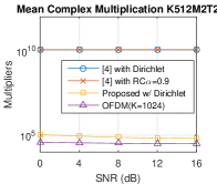
For , the SER and detection complexity results for all schemes are shown in Figs. 2(a) and 2(b), respectively. The trends are similar to those in the previous case. In addition, we observe that the SER performance of the RC filter severely degrades when .
Figs. 1 and 2 reveal that the proposed scheme with the Dirichlet filter requires significantly less detection complexity for GFDM than conventional implementations and achieves superior SER performance. In addition, the choice of affects both the SER performance and detection complexity. Recall that OFDM is a special case of the Dirichlet filter in which . Although the detection complexity drops with OFDM (i.e., the value of is minimized), the SER performance improves with the Dirichlet filter as increases, which may be attributable to the additional frequency diversity obtained from using a larger subcarrier spacing.


V Conclusions
In this paper, we propose a non iterative depth-first sphere-decoding (DFSD) detection scheme of MIMO-GFDM spatial multiplexing (SM) by exploiting frequency-domain (FD) decoupling. We identify a class of prototype filters that enable such FD decoupling and facilitate detection of MIMO-GFDM SM with a significant complexity reduction that was hitherto unrealized. Our simulation results confirm the considerable complexity drop and a symbol-error-rate (SER) improvement with the proposed scheme. These results demonstrate that the Dirichlet filter with the proposed scheme more effectively balances SER performance and detection complexity compared with the widely applied RC filter for MIMO-GFDM systems. In addition, OFDM is demonstrated to be a special case of the proposed scheme, which can be considered a generalization of prototype filter design for FD decoupling. Future directions include prototype filter design for particular properties and the optimal choice of in MIMO-GFDM systems.
References
- [1] N. Michailow, M. Matthé, I. Gaspar, A. Caldevilla, L. Mendes, A. Festag, and G. Fettweis, “Generalized Frequency Division Multiplexing for 5th Generation Cellular Networks,” IEEE Trans. Commun., vol. 62, no. 9, pp. 3045–3061, Sep. 2014.
- [2] N. E. Tunali, M. Wu, C. Dick, and C. Studer, “Linear large-scale MIMO data detection for 5G multi-carrier waveform candidates,” in 2015 49th Asilomar Conf. on Signals, Systems and Computers, Nov 2015, pp. 1149–1153.
- [3] D. Zhang, M. Matthé, L. L. Mendes, and G. Fettweis, “A Study on the Link Level Performance of Advanced Multicarrier Waveforms Under MIMO Wireless Communication Channels,” IEEE Transactions on Wireless Communications, vol. 16, no. 4, pp. 2350–2365, April 2017.
- [4] M. Matthé, I. Gaspar, D. Zhang, and G. Fettweis, “Near-ML Detection for MIMO-GFDM,” in Veh. Technol. Conf. (VTC Fall), 2015 IEEE 82nd, Sep. 2015, pp. 1–2.
- [5] M. Matthé, D. Zhang, and G. Fettweis, “Sphere-decoding aided SIC for MIMO-GFDM: Coded performance analysis,” in 2016 International Symposium on Wireless Communication Systems (ISWCS), Sept 2016, pp. 165–169.
- [6] D. Zhang, M. Matthé, L. L. Mendes, and G. Fettweis, “A Markov chain Monte Carlo algorithm for near-optimum detection of MIMO-GFDM signals,” in Personal, Indoor, and Mobile Radio Commun. (PIMRC), 2015 IEEE 26th Annual Int. Symposium on, Aug 2015, pp. 281–286.
- [7] D. Zhang, L. L. Mendes, M. Matthé, I. S. Gaspar, N. Michailow, and G. P. Fettweis, “Expectation Propagation for Near-Optimum Detection of MIMO-GFDM Signals,” IEEE Trans. Wireless Commun., vol. 15, no. 2, pp. 1045–1062, Feb 2016.
- [8] M. Matthé, D. Zhang, and G. Fettweis, “Iterative Detection using MMSE-PIC Demapping for MIMO-GFDM Systems,” in Eur. Wireless 2016; 22th Eur. Wireless Conf., May 2016, pp. 1–7.
- [9] ——, “Low-Complexity Iterative MMSE-PIC Detection for MIMO-GFDM,” IEEE Transactions on Communications, vol. PP, no. 99, pp. 1–1, 2017.
- [10] M. Simsek, A. Aijaz, M. Dohler, J. Sachs, and G. Fettweis, “5G-Enabled Tactile Internet,” IEEE Journal on Selected Areas in Communications, vol. 34, no. 3, pp. 460–473, March 2016.
- [11] M. Matthé, N. Michailow, I. Gaspar, and G. Fettweis, “Influence of pulse shaping on bit error rate performance and out of band radiation of Generalized Frequency Division Multiplexing,” in Proc. IEEE ICC Workshop, 2014, pp. 43–48.
- [12] D. Wubben, R. Bohnke, V. Kuhn, and K. D. Kammeyer, “MMSE extension of V-BLAST based on sorted QR decomposition,” in 2003 IEEE 58th Vehicular Technology Conference. VTC 2003-Fall (IEEE Cat. No.03CH37484), vol. 1, Oct 2003, pp. 508–512 Vol.1.
- [13] O. Damen, A. Chkeif, and J. C. Belfiore, “Lattice code decoder for space-time codes,” IEEE Communications Letters, vol. 4, no. 5, pp. 161–163, May 2000.
- [14] D. Wubben, R. Bohnke, J. Rinas, V. Kuhn, and K. D. Kammeyer, “Efficient algorithm for decoding layered space-time codes,” Electronics Letters, vol. 37, no. 22, pp. 1348–1350, Oct 2001.
- [15] Y.-P. Lin, S.-M. Phoong, and P. P. Vaidyanathan, Filter Bank Transceivers for OFDM and DMT Systems. New York, NY, USA: Cambridge University Press, 2010.