How to automate a kinematic mount using a 3D printed Arduino-based system
1. Introduction
Over the last years the combination of 3D printing and Arduino has proved to be an efficient and cost-effective way of making experimental equipment, becoming in many occasions an attractive alternative to its commercial counterparts. This combination of Arduino, 3D printed parts and simple hardware have already been used in a system to determine the concentration of dissolved species [1], to provide a carefully controlled dose of a given reagent [2], to characterize easily the spatial profile of a laser beam [3], and to centrifuge a substance for DNA extraction [4], among others.
In all of these cases, expensive and sometimes over-engineered components are substituted by equipment that, despite costing a fraction of its commercial counterpart, can be used to perform state-of-the-art research. Moreover, thanks to the fact that the fabrication time is minimal, the characteristics and quality of the components evolve very fast in the hands of researchers. This evolution process has unexpectedly turned out to be a creative way to engage young minds to research in natural sciences.
In this paper we report the development of a system that can motorize many of the kinematic mounts available nowadays on the market. It combines 3D printed components, simple hardware and electronics, and an Arduino board. The system is intended to add automation capabilities to the Open-Source Optics Library [5] already available on the Internet. The library is composed of a broad selection of optical components ubiquitous in any optics experiment such as lens holders [6], screen/filter holders [7, 8], lab jacks [9], fiber optic holders [10], kinematic mirrors and translation stages [11, 12], and parametric open-source chopper wheels [13], to name a few.
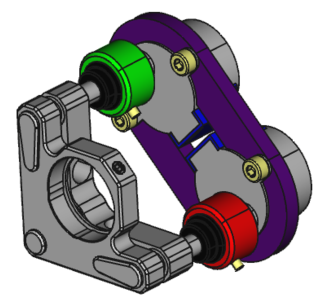
The system we demonstrate here is simple, flexible and cost-effective. The simplicity of the system relies on the components used to implement it. It is composed of a 3D printed plate that supports two stepper motors 28BYJ-48. Its shafts are aligned with the knobs used to tip and tilt the plane of the kinematic mount that supports the optics (see Figure 1). The cylindrical adapter used to couple the shaft to the knob is also 3D printed. An Arduino MEGA controls the motors. In order to simplify the connections with the motor drivers, a shield (Sensor Shield V1.0) provides the capability of controlling up to ten motors simultaneously by sending simple instructions defined by a command table through the serial port.
The hardware and software of the system are flexible and can be easily modified according to the user needs. From the hardware side, since the 3D printed components that couple the system to the kinematic mount were parametrically designed using FreeCAD 0.16 [14], the system is highly tunable by changing only a few parameters on a spreadsheet. Similarly from the software side, the Arduino code is well documented and some usage examples are provided in the *.ino file. The FreeCAD and Arduino source code can be downloaded from the repositories Thingiverse [15] and Github [16], respectively.
The low cost of the system is the byproduct of its simplicity. As a reference, the average cost of fabricating a system composed of four stepper motors for controlling two kinematic mounts is around 30 EUR . The system presented in this letter compares thus favorably with respect to commercial alternatives, since it can be roughly between 5 to 10 times less expensive. However, a word of caution should be added here. Since the system keeps track of the number of steps given by the stepper motor of each channel to estimate its current position, some inaccuracies may appear due to the hysteresis present on the stepper motors. Therefore, the true usefulness of the system presented in this work will depend on its specific aim. Based on our experience in the laboratory in a research institute, we find that the system is suitable for a wealth of applications ranging from teaching to doing high-quality research experiments.
To illustrate and validate the system developed, we consider two scenarios that may require the use of two mirrors supported by two kinematic mounts. The first scenario is the alignment of a laser beam through two reference apertures, and the second scenario is the coupling of light into a multimode or single-mode optical fiber. Both scenarios might be of great interest to experimenters that require to re-align an optical beam or to increase the coupling efficiency of an optical fiber on a daily basis.
2. Results
To validate and test the performance of the motorized system, we have implemented the two experimental schemes shown in Figure 2. We use a HeNe laser, and align the laser beam with the help of two mirrors supported by two kinematic mounts, and .
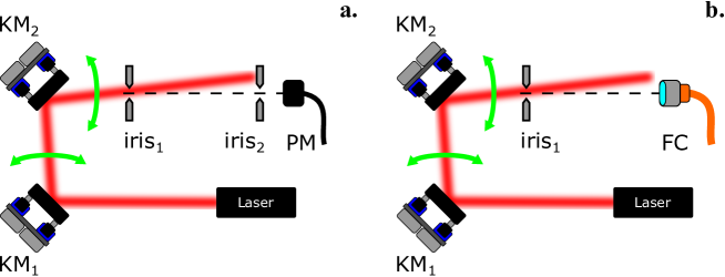
In each experiment, the tip and tilt of each of the two mirrors is automatically controlled using a MATLAB routine. The power after the second iris (Figure 2(a)) or at the output of the fiber (Figure 2(b)) is monitored using a Thorlabs PM100A power meter. After scanning sequentially the tip and subsequently the tilt of both mirrors, the final position of each kinematic mount is set to the position that corresponds to the maximum power registered.
2.1. Alignment of an optical beam with the help of two irises
The experimental scheme is shown in Figure 2(a). The initial position of the mirrors (without using the stepper motors) is set so that the optical beam hits the first iris close to its center. This coarse alignment is mainly driven by the first mirror . Once the starting point is defined, the motors are attached to the kinematic mounts knobs and a simple MATLAB routine is executed where each motor move independently a defined number of steps either in a clock-wise or anti-clockwise direction. The optical power is measured by the detector located after the second iris.
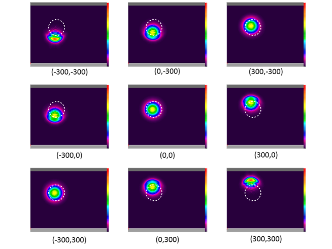
To illustrate a step by step run of the MATLAB routine, a CCD camera is placed just after the second iris and a beam image is acquired for several positions of both motors. Figures 3 and 4 show the beam position registered for a given combination of steps in the X and Y directions, respectively. As a reference, the position of the second iris (set at a given aperture) is indicated by a dashed circle in all images.
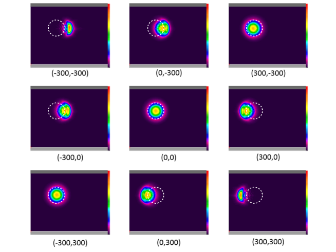
In the example, each motor and is set to move between three different positions separated by 300 steps, so that each motor can move between the absolute positions -300, 0 and 300. As a result, a full scan in the X and Y directions is defined by 9 different positions indicated by the array below each figure.
Notice that the maximum power is registered for the positions , while the positions with opposite angles and correspond to a situation where the effect of one mirror is compensated by the other and the centroid of each beam is slightly shifted to the right or left, respectively.
2.2. Optimizing the coupling efficiency of a light beam into an optical fiber
We replace the second iris of the previous experimental setup by a multi-mode optical fiber (see Figure 2(b)). The aim is to test the performance of the system, and the simple routine written in MATLAB code, for optimizing the coupling of light into an optical fiber. The motors attached to the 3D printed kinematic mounts perform a scan in the X direction, and later on in the Y direction, controlled by a MATLAB program.
Figure 5 shows a table with the data obtained after performing a full scan in both directions. First the X scan provides a power maximum (highlighted), which is used as the starting point for a second scan in the Y direction (highlighted).
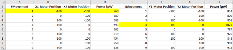
After the scan in the X and Y directions the motors will move to positions and respectively. For this final situation, the recorded power is 1027 . Taking into account that the input power of the laser is 1250 , we obtain that the laser-fiber coupling efficiency is .
3. Discussion
The combination of 3D printing and simple hardware and electronics components is becoming more and more popular as a tool for developing scientific equipment. It offers the possibility to lower significantly the cost of an experiment, and sometimes even more importantly, it helps to reduce dramatically the delivery time of certain components.
| Company | Software | Hardware | Price [ EUR ] |
|---|---|---|---|
| Newport | PicomotorTM | 8806 Picomotor Motorized Blank Plate Mount | 1885 |
| Edmund Optics | Via RS-232 Serial Interface | Motorized Kinematic Mount | 1595 |
| Standa | 8SMC5-USB Stepper and DC Motor Controller | 8MBM24 - Motorized Mirror Mounts | 940 + 699 |
| Physik Instrumente (PI) | PI Mikromove | N-480 PiezoMike Linear Actuator | 2109.03 |
| Thorlabs | K-Cube DC Servo Motor Controller | KS1-Z8 DC Motorized Mirror Mount | 580.41 + 1218.97 |
One important conclusion that is extracted from Table 1 is that worldwide there are only a few companies that sell optical equipment that cover satisfactorily the basic need to automate the alignment of optical systems. In any case, prices are reasonably high, that leads to the need to reduce them using new resources. Precisely our work addresses this last concern, and makes use of 3D printing and simple electronics to lower cost.
Using 3D printed kinematic mounts dramatically reduces the cost, and greatly increases flexibility and adaptability with respect to existing systems. The experimental results obtained support the operation and viability of both the low-cost hardware and the simple open-source software provided.
The convergence of the auto-alignment method is undoubtedly key and essential to ensure its proper functioning. In our case, this convergence is guaranteed by reducing the number of steps of the motors in the feedback loop. In other words, the convergence must be done by the user, who must manually reduce the number of steps. For the same reason, an obvious improvement of our MATLAB routine would be the "automatization" of that convergence, that is, a code designed to converge to the optimal solution that reduces the number of steps of the motors automatically.
Another possible improvement that can be implemented in our code would be the realization of a single feedback loop for the X-Y plane scan. Recall that in our case there are two loops, one for scanning along the X direction and another one for the Y direction. This seems reasonable, since it simulates the alignment that is carried out manually by scientists. But for greater compactness and lower computational cost, a single loop that synchronizes the movement of the four motors could be implemented and be more advantageous.
4. Materials and Methods
We have designed and implemented a system that can provide full automatic control of a vast majority of standard kinematic mounts available on the market. It combines open-source resources such as 3D printing and simple electronics.
A single unit of the system, capable of controlling the tip and tilt of a kinematic mount, is composed of two stepper motors attached to a 3D printed plaque that aligns the knobs of the kinematic mount with the axis of the motors. The axis are coupled to the knobs using a 3D printed knob adapter. The motor drivers are connected to an Arduino MEGA sensor shield (attached to and Arduino MEGA) using Dupont wire jumper cables. Table 2 provides the list of materials required to motorize a kinematic mount for a single channel as well as its estimated cost.
| Component | Quantity | Unit Cost [ EUR ] |
| Parametric plaque (3D printed) | 1 | 2 |
| Knob adapter (3D printed) | 2 | 2 |
| M3 screw | 4 | 0.25 |
| Motor 28BYJ-48 | 2 | 1.5 |
| Arduino MEGA board | 1 | 10.0 |
| Sensor shield for Arduino MEga | 1 | 3.0 |
| Dupont cable (patch of 6 cables) | 2 | 1 |
| TOTAL | 25 |
4.1. Hardware
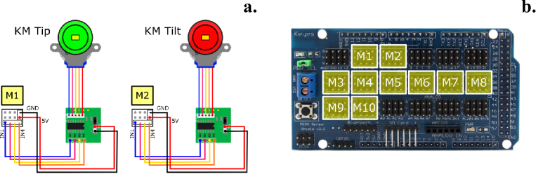
Figure 6(a) provides a connection diagram for a single unit that makes use of two channels (tip and tilt). Each channel is composed of a stepper motor 28BYJ-48, driver electronics and a Dupont cable patch with six wires. Given the number of output pins available on the Arduino sensor shield, the board can be used to control up to five kinematic mounts simultaneously as shown in Figure 6B.
Since the 3D printed components that couple the stepper motors to the kinematic mount were designed using FreeCAD 0.16, the distance between motor axis on the plate, and the inner diameter and height on the knob adapters can be easily modified using a spreadsheet. To attach the motors to the plastic plate, four M4 screws are required, whereas two M3 grub screws are used to secure the knobs to the knob adapters (see figure 7).
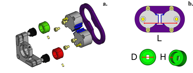
Table 3 provides information on the parameters used for customizing the plate and the knob adapter to fit into four different types of kinematic mounts (see Figure 7(b)). The FreeCAD, FCStd files are available on a Thingiverse [reference].
| Parameter | Variable | PLA | Radiant Dyes | Thorlabs | Liop-Tec |
|---|---|---|---|---|---|
| Plaque axis distance | L | 45.0 | 43.8 | 53.3 | 49.0 |
| Knob diameter | D | 15.0 | 16.1 | 14.5 | 15.0 |
| Knob height | H | 9.0 | 6.0 | 8.0 | 9.0 |
Regarding the motors used, the 28BYJ-48 is a very cheap stepper motor that requires five wires for its connection to the motor driver circuit. The motor can operate in the voltage range from 5V to 12V, and gives 4096 steps per one turn. This number comes from the fact that the internal stepper motor that requires 64 steps to give a complete turn is connected to a set of gears that provide a reduction ratio of 1/64. As a result the 28BYJ-48 requires steps to complete a full turn.
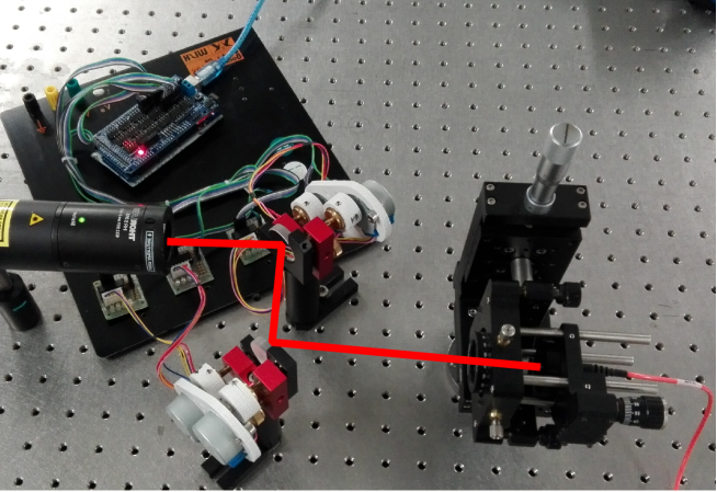
For the sake of illustration, Figure 8 shows the experimental setup corresponding to Figure 2(b), where two kinematic mounts from Radiant Dyes are motorized. Notice that for each channel we have used the following components: one 3D printed supporting plate, two 3D printed knob couplers, two stepper motors and the corresponding driving electronics. In this particular case, the power supplied by the USB port is enough to move the motors. However, in order to control more than four stepper motors simultaneously, it may be necessary to connect the sensor shield to an external power supply.
4.2. Software
In order to provide flexibility and simplicity from the software perspective, each motor is controlled independently by sending a simple instruction defined by a command table through the serial port. A command table is a dictionary of instructions that can be divided into two categories: commands and queries. The first category corresponds to a direct order such as "move stepper motor connected to port 3, half-turn". The second type of command is used to ask information to the device about its status; for example the state of a digital variable, the value of a given counter or the identification string that contains relevant information about the device and its manufacturer.
For reference, table 4 shows the complete list of commands used to control and retrieve information about the status of each motor connected to the Arduino board. Since the status of each motor is determined by a variable that keeps track of the number of steps given by the motor, it is assumed a one-to-one correspondence between the number of steps defined by software and the number of steps given by the axis of the motor. A step on the clock-wise direction adds one unit to the global counter; a step on the counter-clock-wise direction subtracts a unit. To keep the current status of each motor over time, the value of each global counter is stored in the non volatile section of the Arduino (EEPROM memory) so that all the information is available even though the Arduino board is powered off.
| Command | Description |
|---|---|
| STPM:N:ABS:X | move STePper Motor N to ABSolute position X (in steps) |
| STPM:N:REL:X | move STePper Motor N, RELative to current position |
| STPM:N:RST | ReSeT STePper Motor N counter to 0 |
| STPM:N:VEL:X | set STePper Motor N, VELocity to X, where X [1 fast | 10 slow] |
| STPM:N:ST? | retrieve motor N current STatus (position, velocity, state) |
| velocity -> [1 fast | 10 slow] | |
| state -> [0 stop | 1 moving] | |
| STOP | emergency stop. Press reset button to restart |
Since the control method is based on a command table, there are many alternatives to implement the software interface that controls the system. Depending on the application, the user may require to perform simple actions driven by simple commands, or a more elaborate sequence of tasks dependent on external signals or defined by an algorithm with temporal dependence. The former can be implemented by sending commands through the serial port using a serial communication terminal compatible with the RS232 standard such as Termite [reference] and the latter can be implemented using MATLAB, Python or other software.
In our implementation a MATLAB routine communicates with the Arduino board, moves the stepper motors and reads the power detected by a Thorlabs PM100-A detector. The beam auto-alignment procedure is carried out by scanning the X-Y plane in two steps: firstly, the horizontal direction (X) is scanned a certain number of steps while the optical power is measured. Afterwards, the vertical direction (Y) is scanned. In each step the power and motor position are recorded and stored on a .dat file. When the loop finishes, the algorithm returns the motors to the position at which maximum power was detected. The power is first maximized for the X direction and later one for the Y direction.
The number of steps used in each scan is selected initially by the user. Larger ranges lead to a wider scanning of the X-Y plane. This setting is advisable for a first approximation while smaller rotational ranges guarantee the convergence and optimization of the auto-alignment method implemented in MATLAB.
5. Conclusions
In this article we demonstrate a system that can be used to motorize most of the kinematic mounts available on the market. Notwithstanding being implemented using 3D printed components, and Arduino board and simple electronics, the system has proven to be effective, simple, flexible, and low-cost. After performing two different experiments where a laser beam is aligned through two reference points, we can conclude that the system is suitable for applications where optical realignment using flat mirrors mounted on kinematic mounts is required on a periodic basis. Even though the system is initially intended to motorize kinematic mounts, its hardware and software can be easily extended to control other opto-mechanical components such as translation stages.
6. Author Contributions
“L.J.S.S. and G.J. conceived and designed the experiments; L.J.S.S implemented the motorized kinematic mount system; G.J. performed the experiments; L.J.S.S., G.J. and J.P.T. analyzed the data; L.J.S.S., G.J, J.P.T. wrote the paper.
References
- [1] Anzalone, G.C.; Glover, A.G.; Pearce, J.M. Open-Source Colorimeter. Sensors 2013 13, 5338-5346.
- [2] Wijnen, B.; Hunt, E.J.; Anzalone, G.; Pearce, J.M. Open-source Syringe Pump Library, PLoS ONE 2014 9, e107216.
- [3] Hossain, M.A.; Canning J.; Cook, K.; Jamalipour, A. Smartphone laser beam spatial profiler. Opt. Lett. 2015 40, 5156-5159.
- [4] F.Lab’s DIYbio Centrifuge. Available: http://www.thingiverse.com/thing:1175393 (Accessed on 25 Oct 2016).
- [5] Zhang C.; Anzalone, N.C.; Faria R.P.; Pearce, J.M. Open-Source 3D-Printable Optics Equipment, PLoS ONE 2013 8, e59840.
- [6] Open-source lens holder. Available: http://www.thingiverse.com/thing:26752 (Accessed on 24 Oct 2016).
- [7] Square Filter Holder for Open-source Optics. Available: http://www.thingiverse.com/thing:31483 (Accessed on 24 Oct 2016).
- [8] Screen holder for OpenBeam Optical Rail. Available: http://www.thingiverse.com/thing:31403 (Accessed on 24 Oct 2016).
- [9] Open-source Lab jack. Available: http://www.thingiverse.com/thing:28298 (Accessed 24 Oct 2016).
- [10] Open-source fiber optic holder. Available: http://www.thingiverse.com/thing:28187 (Accessed 24 Oct 2016).
- [11] Kinematic mirror/lens mount. Available: http://www.thingiverse.com/thing:30727 (Accessed 24 Oct 2016).
- [12] Salazar-Serrano, L.J; Torres, J.P; Valencia, A. A 3D Printed Toolbox for Opto-Mechanical Components, PLoS ONE 2017 12, e0169832.
- [13] Parametric open-source chopper wheel. Available: http://www.thingiverse.com/thing:28121 (Accessed 24 Oct 2016).
- [14] FreeCAD. Available: http://https://www.freecadweb.org (Accessed 02 Feb 2017).
- [15] Motorized Kinematic Mount. Available: http://https://www.thingiverse.com/thing:2809159 (Accessed 01 Mar 2018).
- [16] Motorized Kinematic Mount (MKM). Available: http://https://github.com/totesalaz/MKM (Accessed 01 Mar 2018).