Subnanosecond magnetization reversal of magnetic nanoparticle driven by chirp microwave field pulse
Abstract
We investigate the magnetization reversal of single-domain magnetic nanoparticle driven by linear down-chirp microwave magnetic field pulse. Numerical simulations based on the Landau-Lifshitz-Gilbert equation reveal that solely down-chirp pulse is capable of inducing subnanosecond magnetization reversal. With certain range of initial frequency and chirp rate, the required field amplitude is much smaller than that of constant-frequency microwave field. The fast reversal is because the down-chirp microwave field acts as an energy source and sink for the magnetic particle before and after crossing over the energy barrier, respectively. Applying a spin-polarized current additively to the system further reduces the microwave field amplitude. Our findings provide a new way to realize low-cost and fast magnetization reversal.
I INTRODUCTION
Magnetization reversal of single-domain magnetic nanoparticle draws significant attentions because of its application in high-density data storage S2000 ; SI2001 ; D2002 and processing B2001 . Fast reversal of single-domain magnetization with minimal energy cost is the ultimate demand in device applications. To achieve high thermal stability and low error rate, high anisotropy materials are used so that magnetic nanoparticles have high energy barrier nature . It is difficult but essential to find out how to achieve fastest magnetization reversal for high-anisotropy magnetic nanoparticles with energy cost as low as possible. Over the last few years, a number of theoretical schemes have been proposed and some of them have been verified by experiment. In the early years, constant magnetic field was used as driving force to reverse the magnetization 1book ; XR2005 , but the reversal time is too long 1book and it suffers from scalability problems because the energy consumption per unit area increases as the device feature size decreases. Since the the discovery of spin transfer torque (STT) STT , people prefer to deploy spin polarized electric current M1998 ; J1999 ; Z2004 ; A2000 ; X2000 ; E1999 ; JA2000 ; R2004 to reverse the magnetization, and devices based on STT magnetization reversal have been fabricated. However, large current density is required for fast reversal so that significant Joule heat shall limit the device durability and reliability of the device HMORISE ; Tshinjo ; Joule . If the direction of the magnetic field or current varies with time in a designed way, the field/current amplitude or switching time can be much lower XR2007 than that of constant field/current. But it is strenuous to generate such kind of fields/currents in practice. Microwave magnetic field, either with or without a polarized electric current, is another controlling knob for magnetization reversal Bertotti ; IEEE ; XR2006 . A microwave of constant frequency itself can reverse a magnetization through synchronization XR2005 . Large field amplitude is required and the reversal process is relatively slow T2016 ; C2003 ; SI2006 ; SO2008 ; TT2013 . Recently, there are several theoretical approaches demonstrating the magnetization reversal by microwaves of time-dependent frequency KR ; ZM ; Suto17 ; GK ; NBarros ; Lcai ; Topical view . However, the existing strategies are either too complicated or lack of clear physical pictures. In this paper, we show that a circularly polarized down-chirp microwave pulse (a microwave pulse whose frequency decreases with time) can effectively reverse a magnetization. For a nanoparticle of a high uniaxial anisotropy (coercive field T), subnanosecond magnetization reversal can be achieved. With proper choice of initial frequency and chirp rate, the microwave field amplitude required for subnanosecond magnetization reversal is only several tens of mT, much smaller than that required for a constant-frequency microwave field. Because through the reversal process, the anisotropy field decreases as the component of magnetization along the easy axis decreases, the intrinsic precessing frequency of the magnetization also decreases. After passing the equator, the intrinsic precessing frequency changes its sign. The down-chirp microwave field acts as an energy source (sink) before (after) the magnetization reaches the equator in the fast magnetization reversal. We further show that linear-polarized down-chirp microwave field pulse is also capable of reversing a magnetization fast. We also demonstrate a spin-polarized current can work together with the down-chirp microwave field pulse so that both applied current density and microwave amplitude are low enough.
II Model and Methods
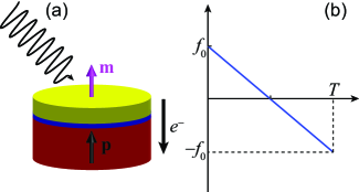
We consider a spin valve with free and fixed ferromagnetic layers and a nonmagnetic spacer in between, as shown schematically in Fig. 1(a). Both fixed and free layers are perpendicularly magnetized. The magnetization direction of the fixed layer is pinned to be upward, ( is the unit vector along direction). The magnetization of free layer is treated as a macrospin with magnetization direction and saturation magnetization . The macrospin approximation is valid for device size smaller than 100 nm Yzhang . The Landau-Lifshitz-Gilbert (LLG) equation governs the magnetization dynamics in the free layer in the presence of spin polarized current and microwave magnetic field XR2005 ; XR2006 ; XR2007 ; T2016
| (1) |
where is the gyromagnetic ratio, is the Gilbert damping constant. The total effective field consists of the microwave magnetic field and the anisotropy field , i.e., . represents the intensity of spin transfer torque (STT) STT ,
| (2) |
where , , , and represent the current density, electron charge, spin polarization of current, and thickness of the free layer, respectively. is the Plank’s constant and is the vacuum permeability. In the following study, the parameters are chosen from typical experiments on the microwave driven magnetization reversal as , T, rad/(Ts), , , nm.
The microwave field and the spin transfer torque are non-conservative forces. They do work on the macrospin. We first consider solely microwave-driven magnetization reversal. Without STT term, the rate of energy change of the macrospin is expressed as
| (3) |
The first term is always negative because of the positive damping factor whereas the second term can be either positive or negative for a time-dependent field. In other words, the microwave field can be either an energy source or an energy sink, depending on the relative angle between the instantaneous magnetization direction and the time derivative of the microwave field.
Due to the easy-axis anisotropy, the magnetization has two stable equilibrium states, , corresponding to two energy minima. The magnetization reversal is to reverse the magnetization from one equilibrium state to the other. Thus, the magnetization has to be driven to overcome an energy maximum at the equator . Before reaches the equator, it gains energy from external forces. After passes the equator, it releases energy through damping or through the negative work done by external forces. For a microwave field, the ideal case for fast magnetization reversal is that the microwave always synchronize to the magnetization motion so that keeps maximal before reaching the equator and keeps minimal after passing the equator. However, this is difficult to achieve in practice. We notice that the internal effective field due to anisotropy is , which corresponds to a resonant frequency proportional to . During a magnetization reversal from to , the resonant frequency first decreases, then reaches 0 at the equator, then increases again with opposite precession direction. This leads us to consider a down-chirp microwave pulse, whose frequency decreases with time. If the rate of frequency change matches the magnetization precession, the microwave field roughly accommodates the magnetization precession, and acts as an energy source (sink) before (after) reaching the equator, so that the magnetization reversal can be fast.
In order to demonstrate the feasibility of above scenario, we apply a circular-polarized down-chirp microwave pulse on the system and numerically solve the LLG equation using MuMax3 package Mumax . The microwave field takes the form
| (4) |
where is the amplitude of the microwave field and is the phase. We consider a linear chirp whose instantaneous frequency is linearly decreasing with time for the changing rate (with unit of s-2) as shown in Fig. 1(b),
| (5) |
where is the initial frequency at . The duration of the microwave pulse is so that the final frequency is .
III Numerical Results
We first investigate the possibility to reverse the magnetization by a down-chirp microwave pulse (DCMWP). At , and the resonant frequency of the magnetization is GHz. Thus, to make the chirp microwave match the precession of as much as possible, we use GHz. Fig. 2(a) shows the time evolution of under three different microwave fields. The red dashed line depicts the reversal by a down-chirp pulse of GHz, ns-2 and =0.045 T. The magnetization reverses fast with a switching time of 0.6 ns (throughout this paper, the switching time is defined as the time reaches ). As a comparison, the evolution of driven by a microwave of constant frequency (CFMW) 21.0 GHz and same amplitude T is shown by the black dash-dotted line. The magnetization only precesses around the initial state and does not reverse. To reverse the magnetization by a microwave of constant frequency within the same time (0.6 ns), the amplitude of the field has to be as large as 0.98 T as shown by the blue solid line, which is unrealistic in practice. Therefore, DCMWP of small amplitude can induce subnanosecond magnetization reversal, showing significant advantage in comparison with conventional constant-frequency microwave driven schemes XR2006 ; T2016 . We then investigate how the switching time depends on the chirp rate and the microwave field amplitude . According to the physical picture discussed in Section II, because the changing rate of the frequency should match the magnetization reversal, the switching time should be closed to the duration of the pulse. Fig. 2(b) shows the -dependence of the switching time for different . The length of the pulse is plotted with green solid line for comparison. For each , there exists a finite window in which the magnetization reversal occurs. Inside the window, the reversal time depends on non-monotonically due to the highly nonlinear magnetization reversal process. However, the reversal times oscillate near the length of the pulse, as shown by the green solid line, which justifies our physical picture. One can also see away from the critical values, the reversal time depends on and weakly. That means a great flexibility in the choice of and as well as the initial frequency, an extra nice property for applications. With ns-2 and T, the initial frequency can be chosen in a wide range from 20.5 GHz to 39 GHz, with corresponding reversal time varying from 0.6 ns to 2 ns.
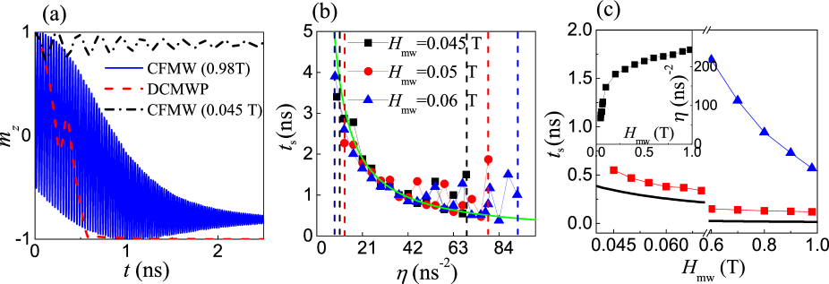
To have a better sense of how good our strategy is, we compare the optimal reversal time of DCMWP of GHz and T (red squares) with the theoretical limit XR2007 of the same field amplitude (black solid line) in Fig. 2(c). The corresponding chirp rates for fastest reversal is shown in the inset. The reversal time of CFMW of GHz is also shown (blue triangles). Below 0.6 T, only DCMWP can switch the magnetization, with a subnanosecond reversal time that is only a little longer than the theoretical limit. For field amplitude larger than 0.6 T, the constant-frequency microwave is also able to switch the magnetization, but the reversal time is much longer.
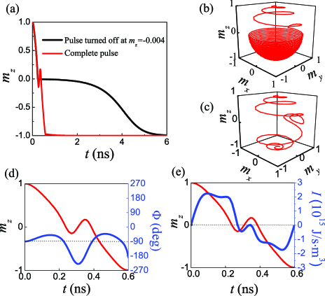
In order to have a better physical understanding of the fast switching under DCMWP, we look at the magnetization process in more detail. The red solid line in Fig. 3(a) shows the magnetization reversal process driven by a down-chirp pulse of GHz, T and ns-2 [which is the same as the parameters used in Fig. 1(a)]. Fig. 3(c) shows the trajectory of magnetization reversal. Before (after) passing the equator, the magnetization rotates in counterclockwise (clockwise) direction, as we discussed before. As a comparison, we turn off the field at the moment that just passes the equator, so that afterwards the energy is purely dissipated by Gilbert damping, i.e., the first term in the right-hand side of Eq. (3). The black line in Fig. 3(a) shows the magnetization reversal when the chirp field is turned off when . It is cleared that the reversal process from the equator to is much slower. Fig. 3(b) shows the corresponding trajectory. Obviously, below the equator, the precessional motion dominates and the longitudinal motion is slower than that in Fig. 3(c). To further justify the physical picture, the down-chirp pulse acts as an energy source (sink) before (after) crossing over the equator, we observe the relative angle between the in-plane components of the magnetization and the microwave field. From Eq. (3), the energy changing rate due to the external field is
| (6) |
where is the angle from (the in-plane component of ) to . We plot by blue line in Fig. 3(d), and by blue line in Fig. 3(e). Before ns, the magnetization reverses quickly from to the equator as shown by the red line. At the same time, is between around . Because the magnetization precesses counterclockwise (), this means is behind . is positive so that the microwave provides energy to the magnetization. When the is , the energy absorption rate reaches the maximum. Also, in Fig. 3(e), the energy changing rate is positive. Between 0.25 ns to 0.35 ns, the magnetization oscillates near the equator because of the complicated nonlinear dynamics. After 0.35 ns, the magnetization reverses from the equator to . At the same time, is again between around . But at this stage the magnetization precesses clockwise (). is in front of . is negative so that the microwave absorbs energy from the magnetization. Also, in Fig. 3(e), the energy changing rate is negative. Thus, the physical picture of fast magnetization reversal by a down-chirp microwave pulse is confirmed: for proper chirp rate and initial frequency, the down-chirp microwave field matches the magnetization precession in a large portion of the reversal process, so that before passing the equator (the energy barrier) the microwave field provides energy to the magnetization and after passing the energy barrier the microwave field absorbs energy from the magnetization with a large energy changing rate.
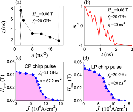
In the above studies, we used circular-polarized (CP) microwaves. Many microwave-generation methods, for example, the coplanar waveguide, generate linear-polarized (LP) microwaves. A LP microwave can be decomposed into the linear combination of two CP microwaves with opposite polarization. So a down-chirp LP microwave should also be capable to switch a magnetization particle. We numerically demonstrate this capability in Fig. 4(a)(b). Figure 4(a) shows the chirp rate () dependence of switching time for a LP microwave of T and GHz. The nanosecond magnetization reversal can be achieved in the window of ns-2. Because of the other CP component, the magnetization dynamics becomes more complicated, as shown in Fig. 4(b), which plots the time evolution of for the optimal ns-2. The complicated magnetization dynamics also results in different optimal initial frequency and chirp rate compared to the CP case. The optimal chirp rate is now ns-2 for LP pulse which is smaller than the CP case, so that the switching time of LP pulse (2 ns) is also longer than that of CP pulse.
The obtained microwave magnetic field 0.045/0.06 T for CP/LP DCMWP is still too high. To further reduce its value, we can simultaneously apply a dc current. An electric current is polarized by the fixed layer so that it has a finite polarization along -direction. Figures 4(c) and (d) show the - phase diagrams of the magnetization reversal for CP and LP chirp microwave pulses respectively together with a dc current . Below (above) the phase boundaries (shown by the blue lines), the switching time is longer (shorter) than 10 ns. The chirp pulses are chosen to be the ones that achieve fast reversal obtained before, i.e., GHz, ns-2 for CP microwave and GHz, ns-2 for LP microwave. If we require the switching time no longer than 10 ns, for magnetization reversal by electric current only, the required current density is about A/cm2; for magnetization reversal by CP/LP down-chirp microwave only, the minimal field amplitude is about 0.0445 T/0.06 T. Naturally, in the presence of both chirp wave and electric current, both and can be smaller than the values above, which provides a large room to design practical magnetization reversal strategies according to the technical details.
IV Discussion and Conclusion
Of course there are some previous studies of magnetization reversal by chirp microwave pulseKR ; ZM ; Suto17 ; GK . But those pulses only provide energy to magnetization just to cross over the equator. After crossing over the equator, the magnetization goes to the reverse state slowly by dissipating the energy due to Gilbert damping. However, as mentioned before, we apply the DCMWP ( frequency profile of the pulse is shown in Fig. 1(b)) such that it acts as energy source (sink) for the magnetization before (after) crossing over the equator which leads fast reversal.
The most challenging part of the DCMWP-driven magnetization reversal is the generation of DCMWP with a wide band width and large chirp rates. There are already several possible techniques for chirp-microwaves generation. In microwave photonics, there are several technologies of generating chirp microwaves Yao ; Sanjeev . Recently, it is found CP microwaves of time dependent frequency can be originated by coupling a magnetic nanoparticle to a pair of weak superconducting links Lcai ; Lcai10 . The time dependency of the microwave frequency can be controlled by voltage. Another way to generate DCMWP is to use spin torque oscillator incorporating a field generating layer. By flowing time varying spin-polarized current through field generating layer, magnetization oscillation is excited. The oscillating magnetic moment in turn induces microwaves of time dependent frequency IEEE ; IEEE2 . Therefore, the spin torque oscillator acts as source of microwave pulse, with the advantage that it is easy to be integrated with the spin valve to achieve good locality and scalability. There is already experimental realization to generate microwave of time dependent frequency ExSTO . The widely-used coplanar waveguide can also be used to generate DCMWP. Using two coplanar waveguides one can generate circular polarized DCMWP Suto17 while one coplanar waveguide can generate linear polarized DCMWP YNOZAKI . Our findings provide improvements for fast magnetization reversal technologies with a clear physical picture, and shine a light on the future development of magnetic data storage and processing devices.
In conclusion, we find a down-chirp microwave pulse can effectively reverse a magnetic nanoparticle. Different from the magnetization reversal driven by the constant-frequency microwaves through synchronization that requires a strong field, the down-chirp microwave provides (absorbs) energy to (from) the magnetization before (after) the energy barrier, so that the reversal can be fast with a low field when the initial frequency and chirp rate are proper. The down-chirp microwave pulse can be used together with a polarized electric current to design more practical reversal strategies.
V ACKNOWLEDGEMENTS
This work was supported by the National Natural Science Foundation of China (Grant No. 11774296) as well as Hong Kong RGC Grants No. 16300117 and No. 16301816. X. S. Wang acknowledges support from UESTC and China Postdoctoral Science Foundation (Grant No.200 2017M612932). M. T. Islam acknowledges the Hong Kong PhD Fellowship.
References
- (1) Shouheng Sun, C. B. Murray, D. Weller, L. Folks, and A. Moser, Science 287, 1989 (2000).
- (2) S. I. Woods, J. R. Kirtley, Shouheng Sun, and R. H. Koch, Phys. Rev. Lett. 87, 137205 (2001).
- (3) D. Zitoun, M. Respaud, M.-C. Fromen, M. J. Casanove, P. Lecante, C. Amiens, and B. Chaudret, Phys. Rev. Lett. 89, 037203 (2002).
- (4) B. Hillebrands and K. Ounadjela, eds., Spin Dynamics in Confined Magnetic Structures I & II, (Springer-Verlag, Berlin, 2001).
- (5) S. Mangin, D. Ravelosona, J. A. Katine1, M. J. Carey, B. D. Terris1 and Eric E. Fullerton. Nature Materials 5, 210-215 (2006).
- (6) A. Hubert and R. Schafer, Magnetic Domains (Springer, Berlin, 1998), Chap. 3.
- (7) Z. Z. Sun and X. R. Wang, Phys. Rev. B 71, 174430 (2005).
- (8) J. C. Slonczewski, J. Magn. Magn. Mater. 159, L1 (1996); L. Berger, Phys. Rev. B 54, 9353 (1996).
- (9) M. Tsoi, A. G. M. Jansen, J. Bass, W.-C. Chiang, M. Seck,V. Tsoi, and P. Wyder, Phys. Rev. Lett. 80, 4281 (1998); Y. B. Bazaliy, B. A. Jones, and S. C. Zhang, Phys. Rev. B 57, R3213 (1998); 69, 094421 (2004).
- (10) J. Sun, J. Magn. Magn. Mater. 202, 157 (1999); Nature (London) 425, 359 (2003).
- (11) J. Z. Sun, Phys. Rev. B 62, 570 (2000); Z. Li and S. Zhang, ibid. 68, 024404 (2003); 69, 134416 (2004); W. Wetzels, G. E. W. Bauer, and O. N. Jouravlev, Phys. Rev. Lett. 96, 127203 (2006).
- (12) A. Brataas, Y. V. Nazarov, and G. E. W. Bauer, Phys. Rev. Lett. 84, 2481 (2000).
- (13) X. Waintal, E. B. Myers, P. W. Brouwer, and D. C. Ralph, Phys. Rev. B 62, 12 317 (2000); M. D. Stiles and A. Zangwill, ibid. 66, 014407 (2002);
- (14) E. B. Myers, D. C. Ralph, J. A. Katine, R. N. Louie, and R. A. Buhrman, Science 285, 867 (1999).
- (15) J. A. Katine, F. J. Albert, R. A. Buhrman, E. B. Myers, and D. C. Ralph, Phys. Rev. Lett. 84, 3149 (2000).
- (16) R. H. Koch, J. A. Katine, and J. Z. Sun, Phys. Rev. Lett. 92, 088302 (2004).
- (17) H. Morise and S. Nakamura, Phys. Rev. B 71, 014439 (2005); T. Taniguchi and H. Imamura, ibid. 78, 224421 (2008).
- (18) Edited by T. Shinjo, Nanomagnetism and Spintronics (Elsevier, Amsterdam, 2009), Chap. 3.
- (19) J. Grollier, V. Cros, H. Jaffr‘es, A. Hamzic, J. M. George, G. Faini, J. B. Youssef, H. LeGall, and A. Fert, Phys. Rev. B 67, 174402 (2003).
- (20) Z. Z. Sun and X. R. Wang, Phys. Rev. Lett. 97, 077205 (2006); 98, 077201 (2007).
- (21) G. Bertotti, C. Serpico, and I. D. Mayergoyz, Phys. Rev. Lett. 86, 724 (2001).
- (22) J.-G. Zhu and Y. Wang, IEEE Trans. Magn. 46, (2010).
- (23) Z. Z. Sun and X. R. Wang, Phys. Rev. B 73, 092416 (2006);74, 132401 (2006).
- (24) T. Taniguchi, D. Saida, Y. Nakatani, and H. Kubota, Phys. Rev. B 93, 014430 (2016).
- (25) C. Thirion, W. Wernsdorfer, and D. Mailly, Nat. Mater. 2, 524 (2003).
- (26) S. I. Denisov, T. V. Lyutyy, P. H¨anggi, and K. N. Trohidou, Phys. Rev. B 74, 104406 (2006).
- (27) S. Okamoto, N. Kikuchi, and O. Kitakami, Appl. Phys. Lett. 93, 102506 (2008).
- (28) T. Tanaka, Y. Otsuka, Y. Furumoto, K. Matsuyama, and Y. Nozaki, J. Appl. Phys. 113, 143908 (2013).
- (29) K. Rivkin and J. B. Ketterson, Appl. Phys. Lett. 89, 252507 (2006).
- (30) Z. Wang and M. Wu, J. Appl. Phys. 105, 093903 (2009).
- (31) H. Suto, T. Kanao, T. Nagasawa, K. Mizushima, and R. Sato, Appl. Phys. Lett. 110, 262403 (2017).
- (32) G. Klughertz, L. Friedland, P.-A. Hervieux, and G. Manfredi, Phys. Rev. B 91, 104433 (2015).
- (33) N. Barros, M. Rassam, H. Jirari, and H. Kachkachi, Phys. Rev. B 83, 144418 (2011); 88, 014421 (2013).
- (34) L. Cai, D. A. Garanin, and E. M. Chudnovsky, Phys. Rev. B 87, 024418 (2013).
- (35) S. Okamoto1, N. Kikuchi, M. Furuta, O. Kitakami and T. Shimatsu, J. Phys. D: Appl. Phys. 48, 353001 (2015).
- (36) arXiv:1802.02415.
- (37) A. Vansteenkiste, J. Leliaert, M. Dvornik, M. Helsen, F. Garcia-Sanchez, and B. Van Waeyenberge, AIP Advances 4, 107133 (2014).
- (38) W. Li and J. Yao, J. Lightwave Technol. 32, 3573 (2014).
- (39) S. K. Raghuwanshi, N. K. Srivastava, and A. Srivastava, Int. J. Electron. 104, 1689 (2017).
- (40) L. Cai, and E. M. Chudnovsky, Phys. Rev. B 82, 104429 (2010).
- (41) J.-G. Zhu, X. Zhu, and Y. Tang, IEEE Trans. Magn. 44, 125 (2008).
- (42) H. Suto, T. Nagasawa, K. Kudo, K. Mizushima, and R. Sato, Nanotechnology 25, 245501 (2014).
- (43) Y. Nozaki, M. Ohta, S. Taharazako, K. Tateishi, S. Yoshimura, and K. Matsuyama, Appl. Phys. Lett. 91, 082510 (2007).