∎
Tel.: +1-505-667-3386
22email: scotthsu@lanl.gov 33institutetext: Samuel J. Langendorf 44institutetext: Los Alamos National Laboratory, Los Alamos, NM 87545
Tel.: +1-505-667-9292
44email: samuel.langendorf@lanl.gov
Magnetized Plasma Target for Plasma-Jet-Driven Magneto-Inertial Fusion
Abstract
We identify the desired characteristics and parameters of a magnetized plasma, possibly with highly tangled, open field lines, that could be a suitable target to be compressed to fusion conditions by a spherically imploding plasma liner [S. C. Hsu et al., IEEE Trans. Plasma Sci. 40, 1287 (2012)] formed by merging hypersonic plasma jets. This concept is known as plasma-jet-driven magneto-inertial fusion (PJMIF). We set requirements on the target and liner such that (a) compressional heating dominates over thermal transport in the target, and (b) magnetic amplification due to compression dominates over dissipation over the entire implosion. We also evaluate the requirements to avoid drift-instability-induced anomalous transport and current-driven anomalous resistivity in the target. Next, we describe possible approaches to create such a magnetized, plasma target. Finally, assuming such a target can be created, we evaluate the feasibility of a proof-of-concept experiment using presently achievable plasma jets to demonstrate target compressional heating at a plasma-liner kinetic energy of kJ (a few hundred times below that needed in a PJMIF reactor).
Keywords:
Plasma liners Plasma jets Magneto-inertial fusion1 Introduction
This paper identifies the desired characteristics and parameters of a magnetized plasma target for plasma-jet-driven magneto-inertial fusion (PJMIF) thio99 ; hsu12ieee ; knapp14 ; langendorf17pop , which is a reactor-friendly magneto-inertial-fusion (MIF, aka magnetized target fusion) lindemuth83 ; kirkpatrick95 ; drake96ft ; lindemuth09 ; wurden16 concept. PJMIF aims to employ a spherically imploding plasma liner, formed by merging an array of hypersonic plasma jets, as a standoff driver to repetitively compress a magnetized target plasma to fusion conditions.
The PJMIF concept was invented in the late 1990s thio99 . PJMIF research began with identifying the parameter space for the plasma liners and plasma jets required to reach fusion conditions thio99 ; knapp , and developing the key concepts needed for plasma guns to produce the required jet parameters thio02 ; cassibry04thesis ; cassibry06 ; thio07 . These concepts include (1) electrode contouring, (2) formation of a pre-ionized plasma slab prior to acceleration, and (3) acceleration of the plasma slab in a non-snowplow mode. In 2004, HyperV Technologies Corp. embarked on designing, fabricating, and testing contoured coaxial plasma guns witherspoon09 to validate these concepts. Plasma-gun development is now continuing with HyperJet Fusion Corporation. Preparation for a demonstration of plasma-liner formation via merging hypersonic plasma jets began in 2009 hsu09 ; hsu12ieee ; hsu12pop ; merritt13 ; merritt14 . A proof-of-concept experiment to demonstrate the latter and develop an understanding of ram-pressure scaling awe11 ; davis12 ; cassibry13 and non-uniformity evolution cassibry12 ; kim13 during plasma-liner convergence is now underway hsu18ieee ; hsu18jfe on the Plasma Liner Experiment (PLX) hsu15jpp at Los Alamos National Laboratory.
However, little research has been devoted thus far to develop a compatible magnetized plasma target that takes advantage of the standoff and high implosion speed ( km/s) of a spherically imploding plasma liner. Most MIF experimental target-development efforts over the past many decades have focused on compact toroids such as spheromaks laberge13 and field-reversed configurations (FRCs) intrator04 ; slough11 , which both must contend with the onerous challenges of global magnetohydrodynamic (MHD) instabilities and anomalous thermal transport associated with micro-instabilities in plasmas. It is worth noting that the best success to date in MIF research, achieved by the Magnetized Liner Inertial Fusion (MagLIF) program slutz10 ; cuneo12ieee at Sandia National Laboratories, is based on the compression of a magnetized plasma target, which was imploded at about 70 km/s to reach multi-keV temperatures gomez14 .
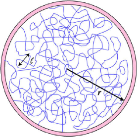
The high implosion speed of plasma liners opens up new options for targets, i.e., , “wall-confined” plasmas (prior to compression) that have Hall magnetization parameters and (where are the ion and electron cyclotron frequencies, respectively, and the ion and electron collision times, respectively) to benefit from magnetized perpendicular thermal transport, while potentially sidestepping the issue of magnetohydrodynamic (MHD) instabilities. The latter statement remains to be explored and demonstrated further. Such a pre-compression, , wall-confined plasma may have closed or highly tangled, open field lines. The latter is depicted in Fig. 1 and was previously discussed as a potential MIF target ryutov09 having a force-free, “magneto-static” tangled magnetic field ryutov02ppcf with initial and instantaneous (during compression) correlation lengths and , respectively. For self-similar target compression, , where and are the initial and instantaneous target radii during compression, respectively.
For the case of closed field lines, magnetized perpendicular thermal transport dominates and is controlled by the ions. For the case of highly tangled, open field lines, parallel thermal transport dominates and is controlled by the electrons. If the electron mean free path is sufficiently short, i.e., , and if the magnetic-field connection length ryutov09 is very long, i.e., , then diffusive electron transport along may allow for a sufficiently long energy-confinement time such that heating due to target compression could dominate over thermal losses. The interesting situation with and highly tangled, open field lines may also exist in astrophysical molecular clouds ryutov05 .
This paper is organized as follows. In the “Fusion-Scale PJMIF Target” section, we describe the requirements of a fusion-scale magnetized plasma target such that (a) compressional heating and magnetic amplification dominate over thermal losses and magnetic dissipation, respectively, and (b) anomalous thermal transport associated with drift instabilities and anomalous resistivity associated with current-driven instabilities are avoided. In the “Possible Approaches to Target Formation” section, we describe conceptual ideas on how such a , PJMIF-compatible target might be formed, with the goal of guiding future research efforts in this area. In the “Feasibility of a Near-Term Target-Heating Experiment” section, we evaluate the feasibility of a subscale experiment to demonstrate target heating via compression by a spherically impoding plasma liner, with kinetic energy kJ, that can be formed by the existing generation of coaxial plasma guns witherspoon17 ; hsu18ieee . The paper ends with “Conclusions and Future Work.”
2 Fusion-Scale PJMIF Target
In this section, we identify the properties of a , magnetized target plasma that is ideally suited for the high implosion speed of spherically imploding plasma liners hsu12ieee . The pre-compression target parameters given in Table 1,
| parameter | value |
|---|---|
| radius | 4 cm |
| density | cm-3 |
| temperature | 80 eV |
| pressure | 25.6 MPa |
| magnetic field | 4.5 T |
| thermal energy | 10.3 kJ |
| thermal/magnetic pressure ratio | 3.2 |
| ion Hall parameter | 0.5 |
| electron Hall parameter | 25 |
| ion mean free path | 0.015 cm |
| electron mean free path | 0.012 cm |
| ion gyro-radius | 0.032 cm |
| electron gyro-radius | 0.00047 cm |
| tangled-field scale | 0.4 cm |
| implosion speed | 100 km/s |
which are modified from the target parameters resulting in 1D calculated energy gain greater than unity upon compression by a plasma liner langendorf17pop , has and . In particular, we are interested in its macro-stability, thermal-transport, and magnetic-dissipation properties during compression, as these properties directly impact its utility as an MIF target plasma.
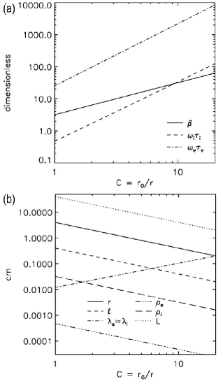
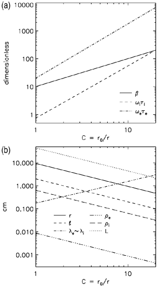
For adiabatic spherical compression (i.e., assuming constant, where is the thermal pressure, is the plasma volume, and polytropic index ), the scalings of target parameters with convergence ratio are , , , , thermal energy , and . Based on these relations and the parameters in Table 1, Fig. 2(a) shows that for the entire implosion (or very nearly so), , , and . Figure 2(b) shows that for the entire implosion up to , , , and . Thus, it is possible that this target avoids MHD instabilities (because ), and exhibits near-classical perpendicular (because and ) and parallel (because and ) thermal transport. These properties are examined in more detail next.
2.1 Macro-stability of a Fusion-Scale Target
One potential advantage of a target plasma is that it may sidestep the issue of fast, virulent MHD instabilities that plague a target before it can even get compressed by a liner. In a target, the magnetic pressure is and remains very small through stagnation (because for adiabatic spherical convergence) compared to the thermal pressure, and therefore hydrodynamic instabilities (e.g., Rayleigh-Taylor or Kelvin-Helmholtz) at the liner/target interface become the primary stability concern, particularly during deceleration just prior to stagnation. This is an important issue, beyond the scope of this paper, requiring much further study in the context of PJMIF. The hydrodynamic disassembly time ( s for the hypothetical target in Table 1) becomes a bottleneck in that the incoming liner must engage and start compressing the target before it can expand very much (also an issue requiring further study). It must also compress the target in a short-enough time such that compressional heating and magnetic amplification overcome the thermal loss rate and magnetic dissipation, respectively, during target compression.
2.2 Thermal Transport in a Fusion-Scale Target
In this subsection, we evaluate the requirement for target compressional heating to dominate over thermal loss rates, which have characteristic time . The evolution of the target thermal energy during compression (ignoring radiative losses, justified below) is
| (1) |
where the first term on the right hand side is compressional heating power . For the latter to dominate over thermal losses, the requirement is
| (2) |
where we assume that . We consider three specific cases governing and require Eq. (2) to be satisfied in each case:
-
1.
For a target with closed field lines, the classical perpendicular ion diffusion time is required, where is the perpendicular ion diffusivity.
-
2.
For a target with closed field lines, the perpendicular anomalous diffusion time is also required, where is the Bohm diffusivity; if anomalous transport does not arise (discussed below), then this condition is not a requirement.
-
3.
For a target with highly tangled, open field lines, the classical parallel electron diffusion time is required, where “(R)” stands for Ryutov ryutov09 and is the parallel electron diffusivity; if, however, adjacent field lines diverge exponentially rechester78 , the effective perpendicular diffusivity may become chandran98 , resulting in a faster thermal loss time , where “(CC)” stands for Chandran and Cowley chandran98 . For the parameters of Table 1, . For , may increase due to mirror-trapping effects chandran98 ; albright01 . See the appendix.
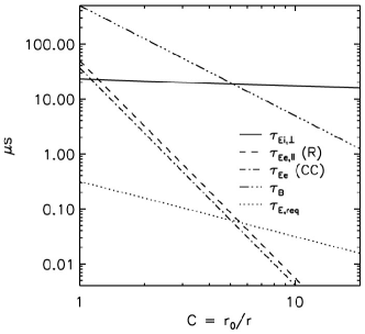
Using the pre-compression target parameters in Table 1 and assuming that ryutov09 throughout the target compression, we calculate , , , , and vs. , assuming adiabatic compression, as shown in Fig. 3.
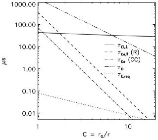
If is too large, then is too small, resulting in violation of the required condition that . For a target with closed field lines ryutov09 , the requirements are comfortably satisfied to . For a target with highly tangled, open field lines, the requirement is challenging to meet at high , although for the parameters of Table 1, the requirement is satisfied to for both and . A caveat is that we assume a gradient scale length for estimating the various diffusion times. If the gradient scale length is in fact a fraction of , then the values for shown in Fig. 3 (except ) will be reduced by the square of that fraction. This caveat applies to all the estimates of energy-diffusion and magnetic-dissipation times in the remainder of the paper. See the appendix for a more-detailed treatment on the limits of target adiabatic heating.
Ignoring radiative losses is justified in the previous analysis. The radiative loss time is , where the bremsstrahlung power nrl-formulary , and therefore . For radiative losses to be negligible, is required. For the parameters of Table 1, at and at , and therefore radiative losses are negligible for the entire implosion to .
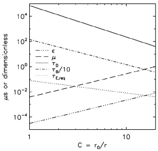
For targets with closed field lines, an important question is whether micro-instabilities will lead to anomalous perpendicular thermal transport faster than , i.e., is there a mechanism leading to that becomes the bottleneck in satisfying Eq. (2)? The diffusivity associated with drift instabilities in an infinite-, collisionless plasma was shown to be el-nadi73 . However, it was later shown ryutov02pop that the result would be different in a high- collisional plasma satisfying the conditions and , where is the drift frequency and is the perturbation wave number along . In shearless systems, the dominant plasma transport arises due to perturbations with the largest possible scale length, i.e., . The two conditions stated above become and , respectively ryutov02pop . When these conditions are satisfied, ryutov02pop , where , and the drift-instability-induced diffusion time is . If the scale size of the magnetic field (i.e., for a tangled field), then the analysis of ryutov02pop should be reconsidered because the dominant transport may not be due to perturbations with . However, and the reduced remain good benchmarks. Figure 4 shows that and are satisfied up to , which means that perpendicular thermal transport would be up to ). Also shown is , which is the nominal worst-case scenario for collisionless, drift-instability-induced transport. It can be seen that , meaning that drift-instability-induced, anomalous transport should not play a role in this implosion regime.
2.3 Magnetic-Energy Dissipation in a Fusion-Scale Target
In this subsection, we evaluate the requirement that magnetic amplification due to compression is much larger than dissipation. The evolution of magnetic energy density is described by ryutov09
| (3) |
where the first term on the right hand side is amplification of magnetic energy density due to compression, i.e., , and is the magnetic-diffusion time over length scale of a tangled field or of a closed field. If magnetic-energy dissipation is negligible, this requires that
| (4) |
where (we evaluate only the more demanding case of the tangled field), is the classical magnetic diffusivity, and the classical perpendicular resistivity.
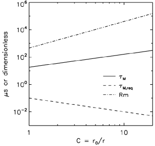
Figure 5 shows that Eq. (4) is well satisfied for all and is more restrictive (although not very) early in the implosion because is lower, and and are higher. Figure 5 also shows that the magnetic Reynolds number (using the more stringent scale ) for the entire target convergence. This means that the magnetic field is frozen into the plasma motion, and that any tangled field that is initially present in the target could indeed be compressed self-similarly as assumed in ryutov09 .
We also evaluate the Nernst flux loss, which arises due to finite and can be expressed as braginskii65 ; mcbride15
| (5) |
where
| (6) |
is the dimensionless Braginskii thermoelectric coefficient braginskii65 , the circumference of the plasma out of which field is being advected, and given in units of V/m. For adiabatic spherical convergence, is independent of , and thus if the Nernst flux loss is negligible initially, it will be negligible for all . For the parameters in Table 1, mWb, , V/m, Wb/s, and the characteristic Nernst flux-loss time is
| (7) |
which is and therefore negligible for the fusion-scale target of Table 1.
Finally, we consider the constraint provided by the condition to avoid current-driven anomalous resistivity davidson75 ,
| (8) |
where is the relative drift speed between electrons and ions, the current density, the electron charge, and the ion thermal speed. This condition is also most restrictive at , for which Eq. (8) can be rewritten as ryutov02pop
| (9) |
where is the pre-compression ion plasma frequency. Using the parameters in Table 1, we obtain the requirement that mm, which is satisfied for the choice mm.
Thus, for the pre-compression, fusion-scale DT target parameters of Table 1, near-adiabatic heating and magnetic flux compression with very small dissipation are theoretically possible up to .
3 Possible Approaches to Target Formation
As mentioned in the “Introduction” section, formation of a , wall-confined magnetized target plasma was previously discussed by D. Ryutov ryutov09 , in which he states: “Creation of the initial plasma with a small-scale, random, magnetic field immersed into it may not be a simple task. The author is not aware of any published papers where formation and characterization of such an object would be documented. An intuitively appealing way for creating such a target would be the use of numerous plasma guns generating small-scale, magnetized plasma bunches and injection of such bunches into a limited volume. This could be a version of the guns envisioned in the plasma liner approach.” In essence, our primary target-formation development path has been identified. We are also interested in forming a target with closed field lines, which may also be explored by the methods discussed next.
A key to creating a , magnetized plasma via merging multiple gun-formed plasmas is potentially via adjustment of the gun parameter , where and are the gun electrical current and the pre-applied poloidal magnetic flux (“bias flux”) linking the two gun electrodes, respectively. Prior research, e.g., yamada90 ; ono99 ; cothran03 , demonstrated that merging two spheromaks (with exceeding some threshold value depending on gun geometry) results in either a spheromak (co-helicity merging) or an FRC (counter-helicity merging), both of which have , which we do not want. At the opposite extreme, where and , as is the case with PLX plasma guns witherspoon11 ; witherspoon17 , which produce , plasma jets hsu12pop because the initially strong magnetic field () at the gun nozzle decays by every few microseconds merritt14 due to the high density ( cm-3) and low eV. Intuitively, these observations suggest that the merging of gun-formed plasmas using an intermediate value of , i.e., , could potentially lead to a merged plasma with , . In an eventual integrated experiment with a plasma liner compressing a target, it is envisioned that the relative initiation times and speeds of the target- and liner-formation jets can be chosen such that the incoming liner is able to engage the stagnated target before the target can expand very much. Further studies are needed to determine whether this is feasible and how much target expansion prior to liner engagement is tolerable.
The above suggests a research path (1) employing 3D single- and two-fluid MHD simulations to explore the parameter space in order to identify whether the formation of , plasmas is possible via merging multiple gun-formed plasmas, and (2) performing experiments merging two gun-formed plasmas over a range of values, guided by the simulations, and characterizing , , and via diagnostic measurements. The initial simulations could be performed, e.g., using the LA-COMPASS (3D MHD) li03 , the USim (multi-fluid MHD) beckwith15 , and/or the FLASH (3D rad-MHD) fryxell00 codes. The initial two-plasma-merging experiments are being planned for execution at the Wisconsin Plasma Physics Laboratory (WiPPL) user facility forest15 . Assuming success in this initial research phase, the next step would be to add external coils or permanent magnets to the existing PLX coaxial guns witherspoon17 in order to apply an appropriate value of , and to form a , magnetized target plasma by merging an array of 6–12 supersonic hydrogen or deuterium plasma jets. This could be performed at the PLX facility hsu15jpp ; hsu18ieee , where, with a higher number of merging jets, we could also study the feasibility of creating tangled fields with .
If it turns out to be impossible or overly difficult to create the , conditions by adjusting , as proposed above, an alternative plan aims to independently apply a magnetic field to an unmagnetized plasma that is first formed by merging , plasma jets hsu12ieee . The magnetic field could potentially be seeded by laser-generated beat-wave current drive welch12 ; welch14 , whereby two lasers with slightly offset frequencies would create a beat wave with a frequency of order the thermal electron plasma frequency. This process would resonantly accelerate thermal electrons, driving electrical current and generating a magnetic field, as has been shown in 2D electromagnetic particle-in-cell simulations welch12 ; welch14 in PJMIF-relevant regimes. This approach may be better suited to create a target with closed field lines, e.g., driving electrical current down one axis of a spherical target to create an azimuthal field. Much research is needed to establish the feasibility of this alternate plan. Proof-of-concept experiments to demonstrate small-scale, beat-wave magnetization (using 1.064- and 1.053-m lasers) of an initially unmagnetized dense plasma ( cm-3) are underway yates17 on the Janus laser at the Jupiter Laser Facility at Lawrence Livermore National Laboratory. The use of charged-particle beams rather than laser-generated beat waves to magnetize a target plasma should also be investigated, e.g., building on prior work that demonstrated FRC formation using an electron beam without a pre-applied magnetic field sethian78prl .
4 Feasibility of a Near-Term, Target-Heating Experiment
In this section, assuming success with liner and target formation based on the the existing generation of plasma guns witherspoon17 ; hsu18ieee , we evaluate whether a near-term, proof-of-concept, target-compression experiment is capable of demonstrating target heating as an important milestone for PJMIF (using the same coaxial plasma guns). This near-term target-heating experiment would use a subscale liner hsu18jfe to compress a subscale target.
A requirement that constrains the target parameters and liner implosion speed is that the liner must act like a good piston, i.e., its penetration into the target must be small compared to the target radius. The penetration is set by the ion–ion frictional slowing distance of a liner ion (e.g., Ar) into the deuterium target plasma (the frictional slowing distance of Ar on electrons is much larger in the regimes of interest). Figure 6
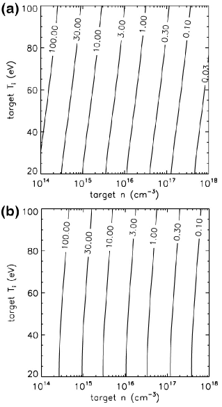
shows contours of Ar–D slowing distance as a function of target and for subscale-relevant km/s and 80 km/s, respectively, where the slowing distance is messer13 and is the slowing rate of argon ions on deuterium plasma (mean-charge state is assumed for both liner and target), as given in the NRL Formulary (p. 31, 2016 edition) nrl-formulary . Anticipating that the subscale target will have a diameter of cm, it is reasonable to require that cm for the liner to act as an effective piston. The piston requirement is easier to satisfy for a fusion-scale target, which has much higher cm-3.
Assuming that the subscale liner will have km/s, Fig. 6(a) shows that a target is required for cm. To determine whether near-term, pre-compression target parameters with cm-3 can be realized, we consider the problem of merging 6–12 deuterium plasma jets (consistent with the achieved plasma-jet parameters witherspoon17 ; hsu18ieee ) to form a “target liner,” which (upon stagnation) results in the subscale target. This is similar to formation of the “compression liner” that will compress the target. The main differences are using fewer jets (6–12 rather than 36–60) and hydrogen or deuterium (rather than argon, krypton, or xenon) for the jet species.
Finally, we repeat the same thermal-transport and magnetic-dissipation analyses presented in the “Fusion-Scale PJMIF Target” section for the subscale target plasma. This sets requirements on the subscale liner to meet the conditions for target heating, while simultaneously satisfying the requirement for the liner to act like a good piston. Finally, we conduct 1D simulations [that also include radiation and equation-of-state (EOS) effects] of the liner compressing the target to verify that target heating occurs.
4.1 Initial Conditions of the Target-Formation Liner
To conduct a 1D simulation of an imploding target liner to form a subscale target plasma, we must first determine its initial conditions, based on the merging of 6–12 near-term, achievable plasma jets. Initial conditions of the target liner consist of its inner radius , thickness , velocity , temperature (where is assumed), and ion number density , where the subscript “TL” refers to target liner. All quantities except are approximately known or derivable from the achievable plasma-jet parameters. The quantity is determined from (and equivalent to) the merging radius of the target-formation jets, according to cassibry13
| (10) |
where is the initial jet radius at the chamber wall (where jets are launched), the initial jet Mach number, the chamber-wall radius, and the number of jets. Equation (10) assumes that the jet expands both radially and axially at the speed . If the jets expand instead at the slower speed , which appears to be a better match to experiments hsu12pop , then
| (11) |
Because the target-formation jets have , this means that , where is the Alfvén speed, and thus we do not additionally consider explicitly jet expansion at speed .
To evaluate , we first need to know . Figure 7 shows the sonic Mach
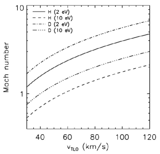
number vs. speed of target-formation jets consisting of hydrogen or deuterium plasma at the bounding cases of 2 and 10 eV. For –100 km/s, Fig. 7 reveals that spans the range –6 for hydrogen at 10 eV to deuterium at 2 eV. For this range of , evaluation of Eqs. (10) and (11) for , 12, and 18 jets, assuming , cm (corresponding to the existing PLX guns/jets), and cm (corresponding to the PLX vacuum chamber), tells us the range of to be expected, as shown in Fig. 8.
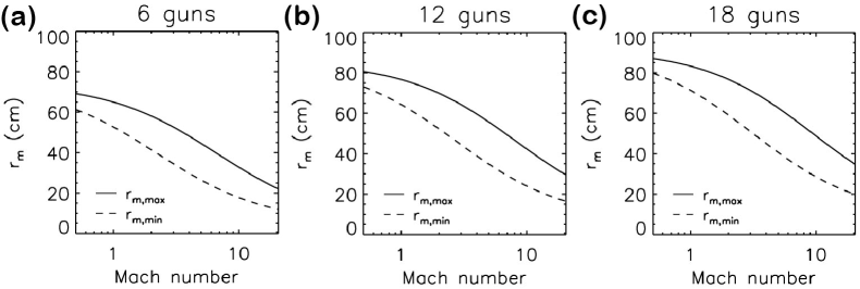
We choose cm, corresponding to and , as a representative case. The value is determined from the amount of jet-volume expansion as the jet travels from to , according to , shown in Fig. 9.
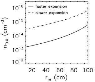
We choose cm-3, corresponding to the slower-expansion case for deuterium at cm (see Fig. 9). Because individual jets are coming together over solid angle, we impose a 1D liner-density profile (for ), where cm and length cm at cm (for the slower-expansion case) and . Thus, the mass of the 1D target liner is equal to the total mass of the jets, i.e., mass . Table 2 summarizes all the parameters (based on expected target-formation jet parameters) that comprise the initial target-liner conditions to be used in a 1D implosion simulation to determine the pre-compression, subscale deuterium-target parameters.
| parameter | value |
|---|---|
| 55 cm | |
| 30 cm | |
| 60 km/s | |
| 3 eV | |
| cm-3 | |
| mass | 1.1 mg |
| kinetic energy | 2.0 kJ |
4.2 Simulation of Target-Liner Implosion to Form a Subscale Target Plasma
We use the initial conditions given in Table 2 to simulate the implosion and stagnation of a target liner, which forms the plasma target, to determine the plasma parameters of the pre-compression target. We use the 1D radiation-hydrodynamics code HELIOS macfarlane06 , which has detailed EOS modeling capabilities. HELIOS cannot model magnetic fields in spherical geometry, and thus we used a multiplier of 0.5 to the code’s Spitzer thermal-conductivity model as a way to phenomenologically capture the effects of magnetized thermal transport in the target-liner implosion and stagnation. The liner is modeled using 300 computational zones (initial average of 1 mm/zone) with automatic zone refinement, separate and evolution (2), both radiation and thermal transport (with a multiplier of 0.5), and non-LTE (local thermodynamic equilibrium) EOS and opacity tables generated using PROPACEOS macfarlane06 . The “vacuum” region initially at cm is modeled identically as the liner itself, also using 300 zones, but with the following differences: (a) cm-3, (b) initial velocity that decreases from to , and (c) thermal-conductivity multipler of 1.0 rather than 0.5. Modeling the “vacuum” region in this manner mitigates the artificial effects of a strong reflected shock arising from the fast-expanding, leading edge of the liner reaching the origin first.
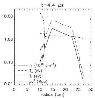
HELIOS simulation results of the 1D radial profiles of several plasma quantities at s are shown in Fig. 10, corresponding to the time of peak thermal pressure.
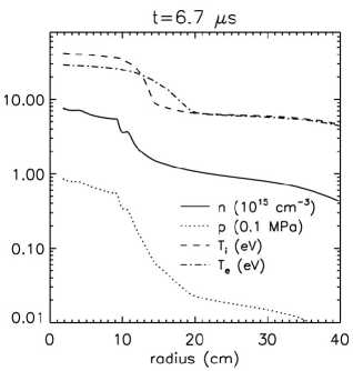
Examining these profiles reveals that target-liner implosion results in a deuterium plasma with peak cm-3, radius cm as inferred from the HWHM of , peak eV, peak eV, and lasting for s as inferred from the FWHM of (not shown here). The inferred subscale, pre-compression deuterium-target parameters and other derived/chosen ones are summarized in Table 3.
| parameter | value |
|---|---|
| 9.4 cm | |
| cm-3 | |
| 42 eV | |
| 29 eV | |
| 0.09 MPa | |
| 1.47 kG | |
| 451 J | |
| 10 | |
| 0.74 | |
| 20 | |
| 0.47 cm | |
| 0.18 cm | |
| 0.64 cm | |
| 0.009 cm | |
| 2.0 cm | |
| 60 km/s |
Referring to Fig. 6(a), we see that the penetration of a 60-km/s imploding argon compression liner into this subscale target is cm, which allows the compression liner to act like a reasonably good piston.
4.3 Properties of the Near-Term, Subscale Target
In this section, we repeat the analyses presented earlier in the “Fusion-Scale PJMIF Target” section to evaluate the thermal-transport and magnetic-dissipation properties of the near-term pre-compression deuterium target of Table 3, in order to determine whether target heating via compression by a subscale plasma liner is possible. Figure 11 shows various dimensionless quantities vs. for spherical adiabatic compression of this subscale deuterium-plasma target.
4.3.1 Macro-stability of a Subscale Target
As before with the fusion-scale target, we aim to create a subscale target that has pre-compression . If we are successful, then MHD instabilities will likely be sidestepped, and the hydrodynamic disassembly time ( s for the hypothetical, subscale target in Table 3) becomes a bottleneck in that the incoming liner must compress the target before it can disassemble (or shortly thereafter). It must also compress the target in a short-enough time that overcomes the thermal loss rate and magnetic dissipation during the target convergence through stagnation.
4.3.2 Thermal Transport in a Subscale Target
Using the initial target parameters in Table 3, we calculate , , , , and vs. , as shown in Fig. 12 (see the discussion in the “Thermal Transport in a Fusion-Scale Target” section).
For a subscale target with closed field lines, perpendicular transport is acceptable for adiabatic heating to . For a subscale target with tangled, open field lines, the electron thermal transport is acceptable for adiabatic heating up to , which should allow for observation of target heating. See the appendix for a more detailed treatment of the limits of target adiabatic heating.
Figure 13 shows the relevant quantities for evaluating anomalous transport in a subscale target (with closed field lines) due to drift instabilities ryutov02pop . As seen in Fig. 13, the condition is violated around (see the discussion in the “Thermal Transport in a Fusion-Scale Target” section). Thus, it is possible that becomes the relevant perpendicular diffusion time for . Nevertheless, up to , and thus drift-instability-induced anomalous transport is not expected to play a substantial role.

Given this analysis, we conclude that in a near-term subscale target-compression experiment (with the initial target conditions of Table 3), adiabatic heating may theoretically be observed up to (depending on transport model used) for the case of tangled, open field lines and to much higher for closed field lines, both assuming that target compression is initiated before it disassembles in a dwell time s. As before, ignoring radiative losses is justified, as at .
4.3.3 Magnetic-Energy Dissipation in a Subscale Target
Figure 14 shows and vs. for the subscale target (see the earlier discussion in the “Magnetic-Energy Dissipation in a Fusion-Scale Target” section), showing that magnetic compression dominates over resistive decay.
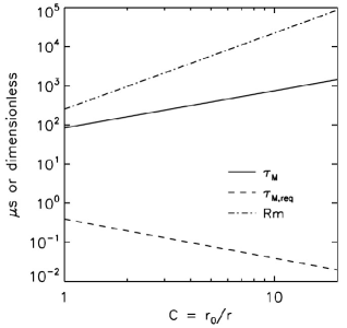
Figure 14 also shows that for the subscale target, indicating that the magnetic field is frozen into the plasma motion and that target compression may lead to self-similar compression of any tangled field that is initially present, as assumed in ryutov09 . Also, using Eq. (7) and the parameters of Table 3, we evaluate the characteristic Nernst flux-loss time s, which is and therefore negligible.
Finally, we consider the condition, given by Eq. (8), to avoid current-driven anomalous resistivity davidson75 in the subscale target. Using the parameters in Table 3, we obtain the requirement from Eq. (9) that mm, which is satisfied by the choice of cm.
4.4 Subscale Plasma-Liner Compression of a Subscale Target
In this subsection, we simulate 1D subscale-plasma-liner compression of the subscale target with parameters given in Table 3. We follow a similar analysis as presented in the “Initial Conditions of the Target-Formation Liner” section to determine and at for the compression liner, assuming achieved PLX-scale plasma-jet parameters. Then, using the compression-liner parameters at , we conduct a 1D HELIOS implosion simulation to determine the compression-liner parameters at the moment it engages the subscale target (with parameters given in Table 3). Finally, we conduct another 1D HELIOS implosion simulation of the subscale liner compressing the subscale target starting at the moment of liner/target engagement.
4.4.1 Compression-Liner Initial Conditions
Similar to the target-liner analysis, to determine the compression-liner merging radius , we first evaluate of the liner as a function of candidate liner species and velocity, as shown in Fig. 15, and vs. , as shown in Fig. 16.
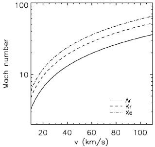
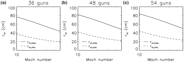
By inspection of Fig. 15, we see that is a representative value for argon (our preferred subscale liner species due to its lower cost compared to krypton and xenon) and expected km/s. By inspection of Fig. 16,
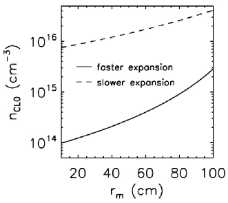
we see that cm for (for the slower-expansion case). There is not a significant difference in for 36 vs. 48 vs. 54 guns. Figure 17 shows the density vs. for argon, and we choose cm-3 for cm. Because jets are coming together, we impose a profile (for ), where cm and cm at cm, and . Thus, the total mass of the 1D compression liner is equal to the total mass of the jets, i.e., liner mass . Table 4 summarizes the initial conditions of the subscale compression liner at .
| parameter | value |
|---|---|
| 40 cm | |
| 10 cm | |
| 60 km/s | |
| 1.5 eV | |
| cm-3 | |
| mass (Ar) | 53.3 mg |
| kinetic energy (Ar) | 96 kJ |
4.4.2 Compression-Liner Parameters at the Moment of Target Engagement
To determine the compression-liner parameters at the moment of target engagement, we perform a 1D HELIOS implosion simulation of the compression liner using the initial conditions given in Table 4. In this simulation, the argon liner is modeled using 300 computational zones (initial average of 0.3 mm/zone) with automatic zone refinement, 2, radiation and thermal transport (with a multiplier of 1.0 for the Spitzer conductivity model), and non-LTE EOS and opacity tables from PROPACEOS. The “vacuum” region, where , is modeled identically as the compression liner, with the following differences: (1) cm-3 and (2) initial velocity . Figure 18 shows the simulation results of the radial profiles of several plasma quantities when the leading edge of the liner reaches cm, which is when it should engage the pre-compression target in Table 3.
4.4.3 Target Heating
Finally, we use idealized versions (i.e., spatially uniform step functions) of the subscale target and liner profiles in Figs. 10 and 18, respectively, to conduct 1D simulations of the subscale liner imploding the subscale target, in order to verify the feasibility of compressional target heating in a near-term, subscale experiment. The simulations include the effects of radiative losses and non-LTE EOS. The idealized initial conditions of the liner engaging the target are given in Table 5. The mass of the idealized compression liner (52.6 mg) agrees well with that of the initial conditions (53.3 mg) in Table 4. However, the mass of the idealized target (0.3 mg) is substantially lower than that of the initial conditions (1.1 mg) of the target liner in Table 2 because we are not including the substantial radial “wing” in density beyond cm (see Fig. 10).
| parameter | target (D) | liner (Ar) |
| (–13 cm) | (–25 cm) | |
| (cm-3) | ||
| (eV) | 40 | 1.3 |
| (eV) | 25 | 1.3 |
| (km/s) | 0 | -60 |
| (MPa) | 0.1 | |
| (MPa) | 0 | 3.4 |
| mass (mg) | 0.3 | 52.6 |
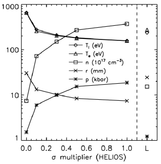
We perform the calculations using both HELIOS and the Langendorf semi-analytic model langendorf17pop . The latter includes more realistic models for estimating the magnetized perpendicular thermal transport for the case of closed field lines (but not the parallel transport for highly tangled, open field lines), and assumes a magnetic field of 1.618 kG (corresponding to ). As mentioned earlier, because HELIOS does not model magnetic fields in spherical geometry, we apply a multiplier to the code’s Spitzer thermal conductivity as a way to model the reduced, perpendicular thermal transport in the target plasma. The HELIOS and Langendorf-model results, using the initial conditions given in Table 5, are shown in Fig. 19 and Table 6. Results from the Langendorf model agree reasonably well with HELIOS results using , with both showing target compressional heating to over 200 eV. Thus, we conclude that compressional target heating in a near-term, subscale experiment is feasible.
The HELIOS case using provides an upper bound on target heating (including radiative losses) to eV (at half the target radius) that compares well with the predicted adiabatic heating to eV. The case with shows that target heating may be observable even without any magnetic insulation. The peak temperatures achieved for all the HELIOS (except the case) and Langendorf results in Table 6 are well below that predicted by adiabatic heating, which was expected up to (for closed field lines), according to Fig. 12; further work is needed to identify the origin of the discrepancy.
| time of peak | target radius at | peak | |||||
| multiplier | reactivity (s) | peak reactivity (cm) | C | (eV) | (eV) | ( cm-3) | (kbar) |
| 3.50 | 3.03 | 4.3 | 658 | 651 | 7.4 | 1.51 | |
| 0.1 | 2.95 | 1.33 | 9.8 | 278 | 257 | 72 | 5.99 |
| 0.3 | 2.85 | 1.02 | 12.7 | 210 | 203 | 150 | 9.96 |
| 0.5 | 2.85 | 0.84 | 15.5 | 182 | 179 | 270 | 15.35 |
| 1.0 | 2.75 | 0.74 | 17.6 | 158 | 156 | 370 | 18.65 |
| Langendorf classical | 2.89 | 2.56 | 5.1 | 262 | 323 | 13.2 | 1.23 |
| Langendorf Bohm | 2.74 | 2.33 | 5.6 | 214 | 219 | 17.4 | 1.20 |
5 Conclusions and Future Work
We describe the properties of a novel, magnetized target plasma (with , , and possibly a tangled field with correlation length much smaller than the target radius) that is well suited for compression by a high-implosion-speed, spherically imploding plasma liner. We show that for the fusion-scale target parameters of Table 1, compressional adiabatic heating is possible to for closed field lines. For a target with highly, tangled open field lines, adiabatic heating to will be challenging to achieve, and the upper limit on is sensitive to the details of the model being used (see also the appendix). We also show that magnetic dissipation, including Nernst effects, should be small, and that anomalous transport and resistivity arising from drift-induced and current-driven instabilities, respectively, are not expected to be important.
Next, we describe a possible approaches to creating a , plasma target, i.e., by merging multiple gun-formed plasmas using the parameter as a control knob. Preparatory efforts are now underway to model and execute an experiment to merge two gun-formed plasmas, with varying , at the WiPPL user facility to test this approach. If this effort is successful, the next step would be to merge 6–12 gun-formed plasmas at PLX to form a subscale target suitable for compression by a subscale liner. Merging 6–12 guns on PLX will allow us to explore the possibility of creating a tangled field with long connection length in the target. We also describe an alternative target-formation approach, i.e., form an unmagnetized target plasma by merging multiple unmagnetized plasma jets, and then independently magnetize the target via laser-generated beat-wave current drive. Proof-of-concept experiments to demonstrate the basic beat-wave magnetization physics are underway using the Janus laser at the Jupiter Laser Facility at Lawrence Livermore National Laboratory. Much research is needed to further assess both these target-formation approaches.
Finally, assuming we are able to form a target with , , and possibly a tangled field, we evaluate whether a near-term, proof-of-concept experiment to demonstrate compressional heating of such a target is feasible using the existing generation of coaxial plasma guns. Using achievable plasma-jet parameters, we estimate the achievable subscale target and liner parameters (Table 5), and show theoretically that for a subscale target with closed field lines, adiabatic heating is theoretically possible to . For a target with tangled, open field lines, adiabatic heating is theoretically possible to to (see also the appendix). Using the parameters of Table 5 as initial conditions, both HELIOS and the Langendorf semi-analytic model predict appreciable target heating assuming closed field lines and perpendicular transport, with good agreement in the peak eV (at half the target radius) when HELIOS uses .
Issues requiring further detailed studies are many, but we mention just a few here as priorities. The highest priority is to perform modeling and experiments to determine whether targets with , , and either closed or open tangled fields can indeed be formed by merging multiple plasma jets. Optimization of target- and compression-liner speeds and their relative firing times from the chamber wall are needed because the target-liner jets expand much more quickly than the compression-liner jets. The optimized parameters should then be used as a guide for integrated 3D radiation-MHD simulations that include the firing and merging of both the target and liner jets, and their subsequent convergence to stagnation. The 3D simulations are also needed to assess the effects of non-uniformities at the liner/target interface, and how much the non-uniformities degrade the target compression and heating due to deceleration-phase Rayleigh-Taylor instabilities (RTI). There may be some mitigating factors for RTI in MIF compared to inertial confinement fusion (ICF) due to there being (i) a strong and possibly sheared magnetic field at the target/liner interface and (ii) much smaller convergence ratio and deceleration magnitude, both of which may provide a larger window of tolerance for RTI in MIF compared to ICF; much further research is needed on this important issue. There is also a need for further detailed study of the thermal transport in a target with highly tangled, open field lines. The Ryutov and C&C scalings used in this paper give substantially different predictions (see also the appendix). Finally, although this paper is largely focused on analysis of the near-term, subscale target-heating experiment, it is worth mentioning that the fusion-scale compression liner may have a dense, cold “afterburner” fuel layer thio99 at the leading edge. This affects the inflight dynamics of the compression liner as well as the subsequent liner/target engagement and target compression, all of which require further study.
The results of this paper motivate and chart a near-term research path toward the subscale demonstration of the formation of a novel magnetized target with and , and the compressional heating of that target using a spherically imploding plasma liner formed by merging hypersonic plasma jets. The existing generation of coaxial plasma guns, with some minor modification (i.e., addition of bias flux), has the technological readiness level to support this development effort, although much gun development is still needed for a fusion-scale demonstration of PJMIF.
Appendix A Target Adiabatic Heating
Following davies17pop but generalizing to spherical geometry, we estimate the temperature , at which which electron thermal losses equals compressional heating for both the Ryutov ryutov09 and C&C chandran98 transport scalings. We use (based on the expressions given in nrl-formulary , where is everywhere in eV and all other variables are in cgs units),
| (12) |
the electron thermal conductivity
| (13) |
and the electron heat flux
| (14) |
where erg/eV, is an adjustment based on chandran98 ; albright01 (discussed further below), and (in cgs units) is a slowly varying function of and . For and , and assuming that electron heat flux dominates over ion heat flux, the instantaneous 0D target energy evolution is (integrating over the target volume and using the divergence theorem)
| (15) |
Using constant and gives
| (16) |
and, after re-arranging,
| (17) |
For adiabatic heating, it is required that the magnitude of the second term on the right hand side of Eq. (17) (compressional heating) dominates over the first (electron heat loss), which leads to the condition
| (18) |
where is the temperature (at a given ) at which compression heating balances electron thermal losses. Based on chandran98 ; albright01 , we assume (Eq. (7) of chandran98 ), which is independent of for adiabatic scaling, when , and we assume when and transport reduction due to mirror trapping becomes applicable. The factor of 5 difference is based on Fig. 7 of albright01 .
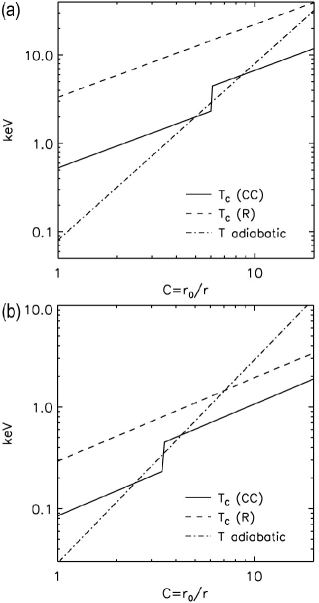
Figures 20(a) and 20(b) show vs. (for both the Ryutov and C&C transport scalings) for the fusion-scale (Table 1) and subscale (Table 3) targets, respectively. Equation (18) defines for the C&C scaling. For the Ryutov scaling, the heat flux is multiplied by a factor by adjusting ; this is due to the effect of the very long connection length of the parallel electron transport. Including the benefit of mirror trapping in the C&C scaling, the peak for adiabatic heating is slightly more pessimistic than that suggested by the simpler analyses in the main text underlying Figs. 3 and 12. The substantial difference between the Ryutov and C&C scalings motivate further studies of the thermal transport in targets with highly tangled, open field lines.
Acknowledgements.
We thank Y. C. F. Thio, I. Golovkin, X.-Z. Tang, and D. Ryutov for discussions and advice, and one of the anonymous referees for pointing out the possible relevance of the more pessimistic Rechester & Rosenbluth transport scaling in a stochastic magnetic field (compared to the Ryutov scaling).References
- (1) Y.C.F. Thio, E. Panarella, R.C. Kirkpatrick, C.E. Knapp, F. Wysocki, P. Parks, G. Schmidt, in Current Trends in International Fusion Research–Proceedings of the Second International Symposium, ed. by E. Panarella (NRC Canada, Ottawa, 1999), p. 113
- (2) S.C. Hsu, T.J. Awe, S. Brockington, A. Case, J.T. Cassibry, G. Kagan, S.J. Messer, M. Stanic, X. Tang, D.R. Welch, F.D. Witherspoon, IEEE Trans. Plasma Sci. 40, 1287 (2012)
- (3) C.E. Knapp, R.C. Kirkpatrick, Phys. Plasmas 21, 070701 (2014)
- (4) S.J. Langendorf, S.C. Hsu, Phys. Plasmas 24, 032704 (2017)
- (5) I.R. Lindemuth, R.C. Kirkpatrick, Nucl. Fusion 23, 263 (1983)
- (6) R.C. Kirkpatrick, I.R. Lindemuth, M.S. Ward, Fusion Tech. 27, 201 (1995)
- (7) R.P. Drake, J.H. Hammer, C.W. Hartman, L.J. Perkins, D.D. Ryutov, Fus. Tech. 30, 310 (1996)
- (8) I.R. Lindemuth, R.E. Siemon, Amer. J. Phys. 77, 407 (2009)
- (9) G.A. Wurden, S.C. Hsu, T.P. Intrator, T.C. Grabowski, J.H. Degnan, M. Domonkos, P.J. Turchi, E.M. Campbell, D.B. Sinars, M.C. Herrmann, R. Betti, B.S. Bauer, I.R. Lindemuth, R.E. Siemon, R.L. Miller, M. Laberge, M. Delage, J. Fusion Energy 35, 69 (2016)
- (10) C.E. Knapp, An implicit smooth particle hydrodynamic code. Ph.D. thesis, University of New Mexico, Albuquerque, NM (2000)
- (11) Y. C. F. Thio, J. T. Cassibry, and T. E. Markusic, “Pulsed Electromagnetic Acceleration of Plasmas,” paper AIAA-2002-3803, 38th AIAA/ASME/SAE/ASEE Joint Propulsion Conference & Exhibit, 2002.
- (12) J. T. Cassibry, “Numerical Modeling Studies of a Coaxial Plasma Accelerator as a Standoff Driver for Magnetized Target Fusion,” Ph.D. Dissertation, Univ. of Alabama in Huntsville, 2004
- (13) J.T. Cassibry, Y.C.F. Thio, S.T. Wu, Phys. Plasmas 13, 053101 (2006)
- (14) Y. C. F. Thio, “Magneto-inertial fusion: An emerging concept for inertial fusion and dense plasmas in ultrahigh magnetic fields,” in Proc. Fifth International Conference in Inertial Fusion Sciences and Applications, Kobe, Japan, 2007; http://www.osti.gov/scitech/biblio/1159661
- (15) F.D. Witherspoon, A. Case, S.J. Messer, R. Bomgardner II, M.W. Phillips, S. Brockington, R. Elton, Rev. Sci. Instrum. 80, 083506 (2009)
- (16) S.C. Hsu, J. Fusion Energy 28, 246 (2009)
- (17) S.C. Hsu, E.C. Merritt, A.L. Moser, T.J. Awe, S.J.E. Brockington, J.S. Davis, C.S. Adams, A. Case, J.T. Cassibry, J.P. Dunn, M.A. Gilmore, A.G. Lynn, S.J. Messer, F.D. Witherspoon, Phys. Plasmas 19, 123514 (2012)
- (18) E.C. Merritt, A.L. Moser, S.C. Hsu, J. Loverich, M. Gilmore, Phys. Rev. Lett. 111, 085003 (2013)
- (19) E.C. Merritt, A.L. Moser, S.C. Hsu, C.S. Adams, J.P. Dunn, A. Miguel Holgado, M.A. Gilmore, Phys. Plasmas 21, 055703 (2014)
- (20) T.J. Awe, C.S. Adams, J.S. Davis, D.S. Hanna, S.C. Hsu, J.T. Cassibry, Phys. Plasmas 18, 072705 (2011)
- (21) J.S. Davis, S.C. Hsu, I.E. Golovkin, J.J. MacFarlane, J.T. Cassibry, Phys. Plasmas 19, 102701 (2012)
- (22) J.T. Cassibry, M. Stanic, S.C. Hsu, Phys. Plasmas 20, 032706 (2013)
- (23) J.T. Cassibry, M. Stanic, S.C. Hsu, F.D. Witherspoon, S.I. Abarzhi, Phys. Plasmas 19, 052702 (2012)
- (24) H. Kim, L. Zhang, R. Samulyak, P. Parks, Phys. Plasmas 20, 022704 (2013)
- (25) S.C. Hsu, S.J. Langendorf, K.C. Yates, J.P. Dunn, S. Brockington, A. Case, E. Cruz, F.D. Witherspoon, M.A. Gilmore, J.T. Cassibry, R. Samulyak, P. Stoltz, K. Schillo, W. Shih, K. Beckwith, Y.C.F. Thio, IEEE Trans. Plasma Sci. PP(99), 1 (2017). DOI 10.1109/TPS.2017.2779421
- (26) S.C. Hsu, Y.C.F. Thio, J. Fusion Energy 37, 103 (2018)
- (27) S.C. Hsu, A.L. Moser, E.C. Merritt, C.S. Adams, J.P. Dunn, S. Brockington, A. Case, M. Gilmore, A.G. Lynn, S.J. Messer, F.D. Witherspoon, J. Plasma Phys. 81, 345810201 (2015)
- (28) M. Laberge, S. Howard, D. Richardson, A. Froese, V. Suponitsky, M. Reynolds, D. Plant, in 2013 IEEE 25th Symposium on Fusion Engineering (SOFE) (2013), pp. 1–7. DOI 10.1109/SOFE.2013.6635495
- (29) T. Intrator, S.Y. Zhang, J.H. Degnan, I. Furno, C. Grabowski, S.C. Hsu, E.L. Ruden, P.G. Sanchez, J.M. Taccetti, M. Tuszewski, W.J. Waganaar, G.A. Wurden, Phys. Plasmas 11, 2580 (2004)
- (30) J. Slough, G. Votroubek, C. Pihl, Nucl. Fusion 51, 053008 (2011)
- (31) S.A. Slutz, et al., Phys. Plasmas 17, 056303 (2010)
- (32) M.E. Cuneo, M.C. Herrmann, D.B. Sinars, S.A. Slutz, W.A. Stygar, R.A. Vesey, A.B. Sefkow, G.A. Rochau, G.A. Chandler, J.E. Bailey, J.L. Porter, R.D. McBride, D.C. Rovang, M.G. Mazarakis, E.P. Yu, D.C. Lamppa, K.J. Peterson, C. Nakhleh, S.B. Hansen, A.J. Lopez, M.E. Savage, C.A. Jennings, M.R. Martin, R.W. Lemke, B.W. Atherton, I.C. Smith, P.K. Rambo, M. Jones, M.R. Lopez, P.J. Christenson, M.A. Sweeney, B. Jones, L.A. McPherson, E. Harding, M.R. Gomez, P.F. Knapp, T.J. Awe, R.J. Leeper, C.L. Ruiz, G.W. Cooper, K.D. Hahn, J. McKenney, A.C. Owen, G.R. McKee, G.T. Leifeste, D.J. Ampleford, E.M. Waisman, A. Harvey-Thompson, R.J. Kaye, M.H. Hess, S.E. Rosenthal, M.K. Matzen, IEEE Trans. Plasma Sci. 40, 3222 (2012)
- (33) M.R. Gomez, S.A. Slutz, A.B. Sefkow, D.B. Sinars, K.D. Hahn, S.B. Hansen, E.C. Harding, P.F. Knapp, P.F. Schmit, C.A. Jennings, T.J. Awe, M. Geissel, D.C. Rovang, G.A. Chandler, G.W. Cooper, M.E. Cuneo, A.J. Harvey-Thompson, M.C. Herrmann, M.H. Hess, O. Johns, D.C. Lamppa, M.R. Martin, R.D. McBride, K.J. Peterson, J.L. Porter, G.K. Robertson, G.A. Rochau, C.L. Ruiz, M.E. Savage, I.C. Smith, W.A. Stygar, R.A. Vesey, Phys. Rev. Lett. 113, 155003 (2014)
- (34) D.D. Ryutov, Fus. Sci. Tech. 56, 1489 (2009)
- (35) D.D. Ryutov, B.A. Remington, Plasma Phys. Control. Fus. 44, B407 (2002)
- (36) D.D. Ryutov, J.O. Kane, A. Mizuta, M.W. Pound, B.A. Remington, Astrophys. Space Sci. 298, 183 (2005)
- (37) F.D. Witherspoon, S. Brockington, A. Case, E. Cruz, M. Luna, Y.C.F. Thio, Bull. Amer. Phys. Soc. 62, 324 (2017)
- (38) A.B. Rechester, M.N. Rosenbluth, Phys. Rev. Lett. 40, 38 (1978)
- (39) B.D.G. Chandran, S.C. Cowley, Phys. Rev. Lett. 80, 3077 (1998)
- (40) B.J. Albright, B.D.G. Chandran, S.C. Cowley, M. Loh, Phys. Plasmas 8, 777 (2001)
- (41) J. D. Huba, NRL Plasma Formulary, 2016.
- (42) A. El Nadi, M.N. Rosenbluth, Phys. Fluids 16, 2036 (1973)
- (43) D.D. Ryutov, Phys. Plasmas 9, 4085 (2002)
- (44) S.I. Braginskii, in Reviews of Plasma Physics, Vol. I, ed. by M.A. Leontovich (Consultants Bureau, New York, 1965), p. 205
- (45) R.D. McBride, S.A. Slutz, Phys. Plasmas 22, 052708 (2015)
- (46) R.C. Davidson, N.T. Gladd, Phys. Fluids 18, 1327 (1975)
- (47) M. Yamada, Y. Ono, A. Hayakawa, M. Katsurai, F.W. Perkins, Phys. Rev. Lett. 65, 721 (1990)
- (48) Y. Ono, M. Inomoto, Y. Ueda, T. Matsuyama, T. Okazaki, Nucl. Fusion 39, 2001 (1999)
- (49) C.D. Cothran, A. Falk, A. Fefferman, M. Landreman, M.R. Brown, M.J. Schaffer, Phys. Plasmas 10, 1748 (2003)
- (50) F.D. Witherspoon, S. Brockington, A. Case, S.J. Messer, L. Wu, R. Elton, S.C. Hsu, J.T. Cassibry, M.A. Gilmore, Bull. Amer. Phys. Soc. 56, 311 (2011)
- (51) S. Li and H. Li, “A Modern Code Solving Magneto-hydrodynamic or Hydrodynamic Equations,” LANL Technical Report, LA-UR-03-8926 (2003).
- (52) K. Beckwith, S.A. Veitzer, S. McCormick, J. Ruge, L.N. Olson, J.C. Cahoun, IEEE Trans. Plasma Sci. 43, 957 (2015)
- (53) B. Fryxell, K. Olson, P. Ricker, F.X. Timmes, M. Zingale, D.Q. Lamb, P. MacNeice, R. Rosner, J.W. Truran, H. Tufo, Astrophys. J. Suppl. Ser. 131, 273 (2000)
- (54) C.B. Forest, K. Flanagan, M. Brookhard, M. Clark, C.M. Cooper, V. Désangles, J. Egedal, D. Endrizzi, I.V. Khalzov, H. Li, M. Miesch, J. Milhone, M. Nornberg, J. Olson, E. Peterson, F. Roseler, A. Schekochihin, O. Schmitz, R. Siller, A. Spitkovsky, A. Stemo, J. Wallace, D. Weisberg, E. Zweibel, J. Plasma Physics 81, 345810501 (2015)
- (55) D.R. Welch, T.C. Genoni, C. Thoma, N. Bruner, D.V. Rose, S.C. Hsu, Phys. Rev. Lett. 109, 225002 (2012)
- (56) D.R. Welch, T.C. Genoni, C. Thoma, D.V. Rose, S.C. Hsu, Phys. Plasmas 21, 032704 (2014)
- (57) K. Yates, S. Hsu, D. Montgomery, J. Dunn, S. Langendorf, B. Pollock, T. Johnson, D. Welch, C. Thoma, Bull. Amer. Phys. Soc. 62, 394 (2017)
- (58) J.D. Sethian, K.A. Gerber, D.N. Spector, A.E. Robson, Phys. Rev. Lett. 41, 798 (1978)
- (59) S. Messer, A. Case, L. Wu, S. Brockington, F.D. Witherspoon, Phys. Plasmas 20(3), 032306 (2013)
- (60) J.J. MacFarlane, I.E. Golovkin, P.R. Woodruff, J. Quant. Spect. Rad. Transfer 99, 381 (2006)
- (61) J.R. Davies, D.H. Barnak, E.M. Campbell, P.Y. Chang, A.B. Sefkow, K.J. Peterson, D.B. Sinars, M.R. Weis, Phys. Plasmas 24, 062701 (2017)