11email: steve.tuenofotso@univ-paris-est.fr, 11email: laleau@u-pec.fr 22institutetext: Télécom SudParis, SAMOVAR-CNRS, Evry, France,
22email: amel.mammar@telecom-sudparis.eu 33institutetext: Université de Sherbrooke, GRIL, Québec, Canada,
33email: Marc.Frappier@usherbrooke.ca 33email: Steve.Jeffrey.Tueno.Fotso@USherbrooke.ca
SysML/KAOS Domain Models and B System Specifications
Abstract
In this paper, we use a combination of the SysML/KAOS requirements engineering method, an extension of SysML, with concepts of the KAOS goal model, and of the B System formal method. Translation rules from a SysML/KAOS goal model to a B System specification have been defined. They allow to obtain a skeleton of the B System specification. To complete it, we have defined a language to express the domain model associated to the goal model. The translation of this domain model gives the structural part of the B System specification. The contribution of this paper is the description of translation rules from SysML/KAOS domain models to B System specifications. We also present the formal verification of these rules and we describe an open source tool that implements the languages and the rules. Finally, we provide a review of the application of the SysML/KAOS method on case studies such as for the formal specification of the hybrid ERTMS/ETCS level 3 standard.
Keywords:
Domain Modeling, Ontologies, B System, Requirements Engineering, SysML/KAOS, Event-B1 Context
1.1 SysML/KAOS
Requirements engineering focuses on elicitation, analysis, verification and validation of requirements. The KAOS method [1] proposes to represent the requirements in the form of goals described through five sub-models of which the two main ones are: the goal model for the representation of requirements to be satisfied by the system and of expectations with regard to the environment through a hierarchy of goals and the object model which uses the UML class diagram for the representation of the domain vocabulary. The hierarchy is built through a succession of refinements using two main operators: AND and OR. An AND refinement decomposes a goal into subgoals, and all of them must be achieved to realise the parent goal. Dually, an OR refinement decomposes a goal into subgoals such that the achievement of only one of them is sufficient for the accomplishment of the parent goal. Requirements and expectations correspond to the lowest level goals of the model.
KAOS offers no mechanism to maintain a strong traceability between requirements and design deliverables, making it difficult to validate them against the needs formulated. SysML/KAOS [2, 3] addresses this issue by adding to KAOS the SysML UML profile specially designed by the Object Management Group (OMG) for the analysis and specification of complex systems. SysML allows for the capturing of requirements and the maintaining of traceability links between those requirements and design deliverables, but it does not define a precise syntax for requirements specification. SysML/KAOS therefore proposes to extend the SysML metamodel in order to allow the representation of requirements using the KAOS expressivity.
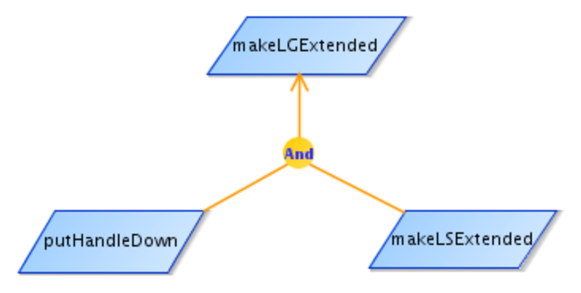
Our case study deals with the landing gear system of an aircraft which can be retracted (respectively extended) through a handle [4]. Figure 1 is an excerpt from its goal diagram focused on the purpose of landing gear expansion (makeLGExtended). To achieve it, the handle must be put down (putHandleDown) and landing gear sets must be extended (makeLSExtended). We assume that each aircraft has one landing gear system.
1.2 Event-B and B System
Event-B is an industrial-strength formal method for system modeling [5]. It is used to incrementally construct a system specification, using refinement, and to prove properties. An Event-B model includes a static part called context and a dynamic part called machine. The context contains the declarations of abstract and enumerated sets, constants and axioms. The machine contains variables, invariants and events. A machine can refine another machine, a context can extend others contexts and a machine can see contexts. Gluing invariants are invariants that capture links between variables defined within a machine and those appearing in more abstract ones. B System is an Event-B syntactic variant proposed by ClearSy, an industrial partner in the FORMOSE project [6], and supported by Atelier B [7].
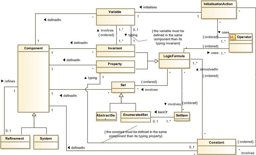
Figure 2 is
a metamodel of the B System language restricted to concepts that are relevant to us.
A B System specification
consists of components (instances of Component). Each component can be either a system or a refinement and it may define static or dynamic elements. A refinement is a component which refines another one in order to access the elements defined in it and to reuse them for new constructions.
Constants, abstract and enumerated sets, and their properties, constitute the static part.
The dynamic part includes the representation of the system state using variables constrained through invariants and initialised through initialisation actions. Properties and invariants can be categorised as instances of LogicFormula.
In our case, it is sufficient to consider that logic formulas are successions of operands in relation through operators. Thus,
an instance of LogicFormula references
its operators (instances of Operator) and its operands that may be instances of Variable, Constant, Set or SetItem.
Operators include, but not limited to 111The full list can be found in [8], Inclusion_OP which is used to assert that the first operand is a subset of the second operand () and Belonging_OP which is used to assert that the first operand is an element of the second operand () and BecomeEqual2SetOf_OP which is used to initialize a variable as a set of elements ().
In the rest of this paper, target is used in place of B System.
1.3 Formalisation of SysML/KAOS Goal Models
The formalisation of SysML/KAOS goal models is the focus of the work done by [9]. The proposed rules allow the generation of a formal model whose structure reflects the hierarchy of the SysML/KAOS goal diagram : one component is associated with each hierarchy level; this component defines one event for each goal. The semantics of refinement links between goals is expressed in the formal specification with a set of proof obligations which complement the standard proof obligations for invariant preservation and for event actions feasibility [5]. Regarding the new proof obligations, they depend on the goal refinement operator used. For an abstract goal and two concrete goals and : 222For an event G, G_Guard represents the guards of G and G_Post represents the post condition of its actions.
-
•
For the AND operator, the proof obligations are
-
•
-
•
-
•
-
•
-
•
For the OR operator, they are
-
•
-
•
-
•
-
•
-
•
-
•
-
•
-
•
For the MILESTONE operator, they are
-
•
-
•
-
•
(each system state, corresponding to the post condition of , must be followed, at least once in the future, by a system state enabling )
-
•
Nevertheless, the generated specification does not contain the system structure, composed of variables, constrained by an invariant, and constants, constrained by properties.
1.4 The SysML/KAOS Domain Modeling Language
Domain models in SysML/KAOS are represented using ontologies. These ontologies are expressed using the SysML/KAOS domain modeling language [10, 11], built based on OWL [12] and PLIB [13], two well-known and complementary ontology modeling formalisms.
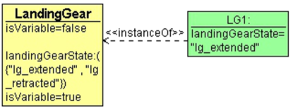
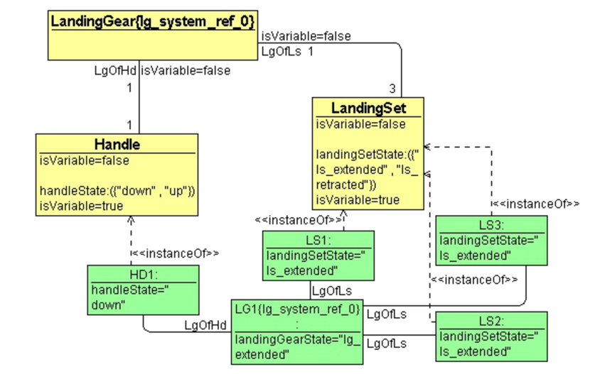
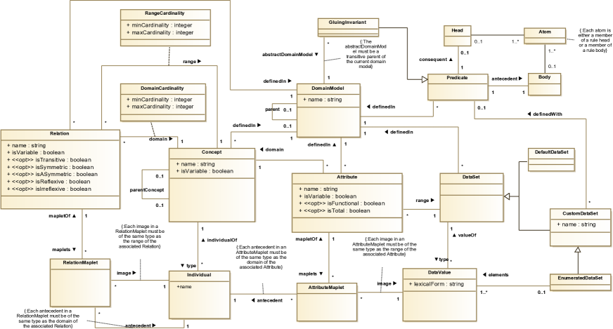
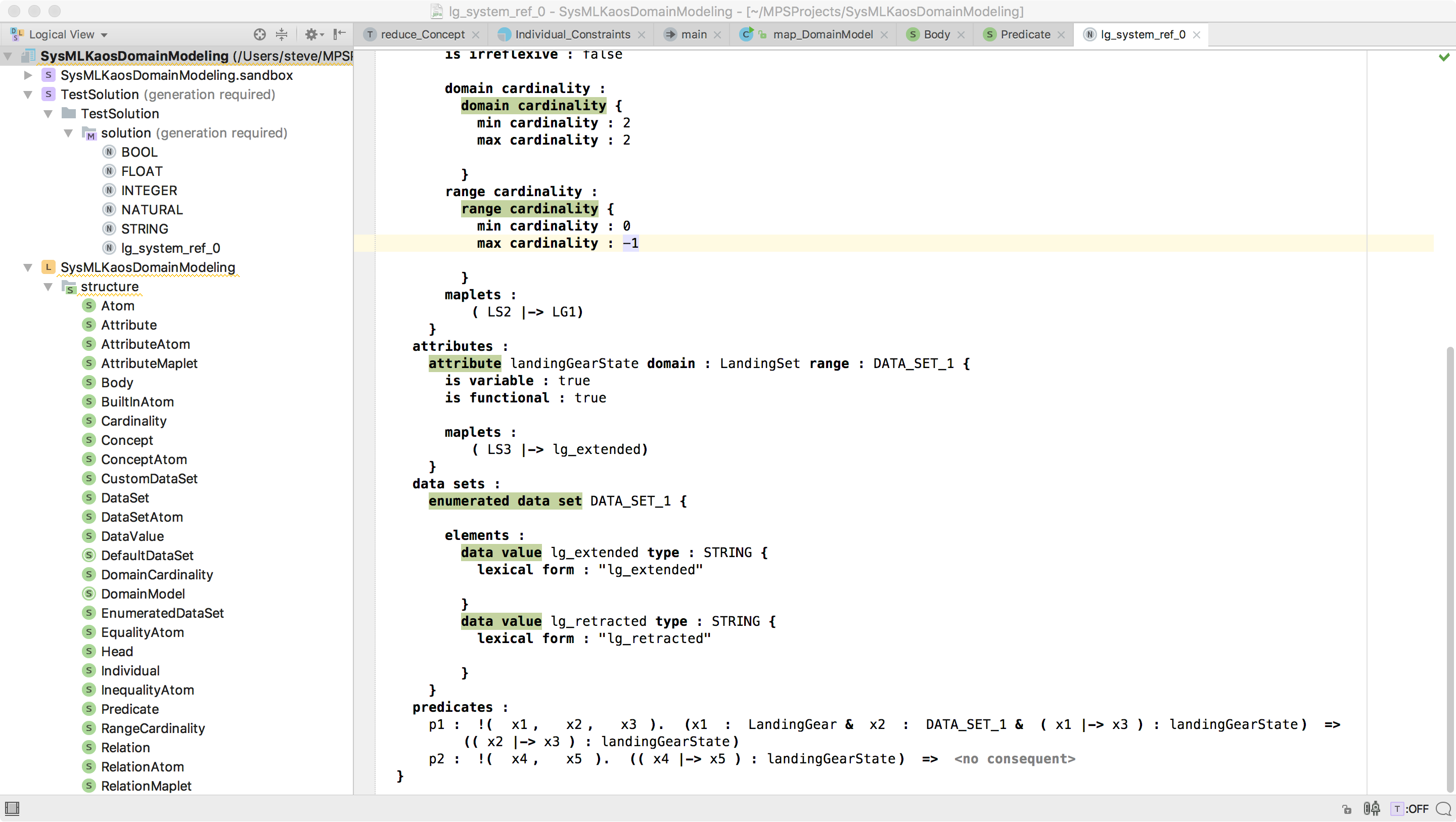
Figure 3 represents the SysML/KAOS domain model associated with the root level of the landing gear system goal model of Fig. 1, and Fig. 4 represents the one associated with the first refinement level. They are illustrated using the syntax proposed by OWLGred [14] and, for readability purposes, we have decided to hide optional characteristics representation. It should be noted that the individualOf association is illustrated, through OWLGred, as a stereotyped link with the tag <<instanceOf>>.
Figure 5 is an excerpt from the metamodel associated with the SysML/KAOS domain modeling language. Each domain model is associated with a level of refinement of the SysML/KAOS goal diagram and is likely to have as its parent, through the parent association, another domain model. For example, the domain model lg_system_ref_1 (Fig. 4) refines lg_system_ref_0 (Fig. 3). We use the notion of concept (instance of Concept) to designate an instantiable universal or a collection of individuals with common properties. A concept can be declared variable (isVariable=TRUE) when the set of its individuals can be updated by adding or deleting individuals.. Otherwise, it is considered to be constant (isVariable=FALSE). For example, in lg_system_ref_0, the landing gear entity is modeled as an instance of Concept named LandingGear. As in the case study adding or deleting a landing gear is not considered, the property isVariable of LandingGear is set to false. Instances of Relation are used to capture links between concepts, and instances of Attribute capture links between concepts and data sets. The most basic way to build an instance of DataSet is by listing its elements. This can be done through the DataSet specialization called EnumeratedDataSet. A relation or an attribute can be declared variable if the list of maplets related to it is likely to change over time. Otherwise, it is considered to be constant. For example, the possible states of a landing gear are modeled by an instance of Attribute named landingGearState, having LandingGear as domain and as range an instance of EnumeratedDataSet containing two instances of DataValue of type STRING: lg_extended for the extended state and lg_retracted for the retracted state. Its isVariable property is set to true, since it is possible to dynamically change the state of a landing gear. Furthermore, the association between landing sets and landing gears, in lg_system_ref_1, is modeled as an instance of Relation named LgOfLs. Since the association of a landing set to a landing gear cannot be changed dynamically, the property isVariable of LgOfLs is set to false.
Each instance of DomainCardinality (respectively RangeCardinality) makes it possible to define, for an instance of Relation re, the minimum and maximum limits of the number of instances of Individual, having the domain (respectively range) of re as type, that can be put in relation with one instance of Individual, having the range (respectively domain) of re as type. For example, in lg_system_ref_1, the instance of DomainCardinality associated with LgOfLs has its minCardinality and maxCardinality properties set to 1. Instances of RelationMaplet are used to define associations between instances of Individual through instances of Relation. Instances of AttributeMaplet play the same role for attributes. For example, in lg_system_ref_1, there are three instances of RelationMaplet to model the association of the landing gear LG1 to the landing sets LS1, LS2 and LS3, each having as image LG1 and as antecedent the corresponding LandingSet individual.
The notion of Predicate is used to represent constraints between different elements of the domain model in the form of Horn clauses: each predicate has a body which represents its antecedent and a head which represents its consequent, body and head designating conjunctions of atoms. A data set can be declared abstractly, as an instance of CustomDataSet, and defined with a predicate. GluingInvariant, specialization of Predicate, is used to represent links between variables and constants defined within a domain model and those appearing in more abstract domain models, transitively linked to it through the parent association. Gluing invariants are extremely important because they capture relationships between abstract and concrete data during refinement and are used to discharge proof obligations. The following gluing invariant is associated with our case study: if there is at least one landing set having the retracted state, then the state of LG1 is retracted
| (1) |
2 Existing Approaches for the Formalization of Domain Models
In [15], an approach is proposed for the automatic extraction of domain knowledge, as OWL ontologies, from Z/Object-Z (OZ) models [16] : OZ types and classes are transformed into OWL classes. Relations and functions are transformed into OWL properties, with the cardinality restricted to 1 for total functions and the maxCardinality restricted to 1 for partial functions. OZ constants are translated into OWL individuals. Rules are also proposed for subsets and state schemas. A similar approach is proposed in [17], for the extraction of DAML ontologies [18] from Z models. These approaches are interested in correspondence links between formal methods and ontologies, but their rules are restricted to the extraction of domain model elements from formal specifications. Furthermore, all elements extracted from a formal model are defined within a single ontology component, while in our approach, we work on the opposite direction: each ontology refinement level is used to generate a formal model component and links between domain models give links between formal components.
In [19], domain is modeled by defining agents, business entities and relations between them. The paper proposes rules to translate domain models so designed into Event-B specifications: agents are transformed into machines, business entities are transformed into sets, and relations are transformed into Event-B variable relations. These rules are certainly sufficient for domain models of interest for [19], but they are very far from covering the extent of the SysML/KAOS domain modeling language.
Some rules for passing from an OWL ontology representing a domain model to Event-B specifications are proposed in [20], in [21] and through a case study in [3]. In [21], the proposed rules requires the generation of an ACE (Attempto Controlled English) version of the OWL ontology which serves as the basis for the development of the Event-B specification. This is done through a step called OWL verbalization. The verbalization method transforms OWL individuals into capitalized proper names, classes into common names, and properties into active and passive verbs. Once the verbalization process has been completed, [21] proposes a set of rules for obtaining the Event-B specification: classes are translated to Event-B sets, properties are translated to relations, etc. In [20], domain properties are described through data-oriented requirements for concepts, attributes and associations and through constraint-oriented requirements for axioms. Possible states of a variable element are represented using UML state machines. Concepts, attributes and associations arising from data-oriented requirements are modeled as UML class diagrams and translated to Event-B using UML-B [22]: nouns and attributes are represented as UML classes and relationships between nouns are represented as UML associations. UML-B is also used for the translation of state machines to Event-B variables, invariants and events. The approaches in [20] and [21] require a manual transformation of the ontology before the possible application of translation rules to obtain the formal specifications: In [20], it is necessary to convert OWL ontologies into UML diagrams. In [21], the proposal requires the generation of a controlled English version of the OWL ontology. Furthermore, since the OWL formalism supports weak typing and multiple inheritance, the approaches define a unique Event-B abstract set named Thing. Thus, all sets, corresponding to OWL classes, are defined as subsets of Thing. Our formalism, on the other hand, imposes strong typing and simple inheritance; which makes it possible to translate some concepts into Event-B abstract sets. In [3], the case study reveals three translation rules: each ontology class, having no individual, is modeled as an Event-B abstract set. If the class has individuals, then it is modeled as an enumerated set. Finally, each object property between two classes is modeled as a constant defined as a relation. Several shortcomings are common to these approaches: the provided rules do not take into account the refinement links between model parts. Furthermore, they have not been implemented or formally verified and they are provided in an informal way that does not allow the assesment of their quality and consistency. Finally, the approaches are far from covering the extent of the SysML/KAOS domain modeling language and they are only interested in static domain knowledge (they do not distinguish what gives rise to formal constants or variables).
Several works have been done on the translation of UML diagrams into B specifications such as [23, 22]. They have obviously inspired many of our rules, like those dealing with the translation of classes (concepts) and of associations (attributes and relations). But, our work differs from them because of the distinctions between ontologies and UML diagrams: within an ontology, concepts or classes and their instances are represented within the same model as well as the predicates defining domain constraints. Moreover, these studies are most often interested in the translation of model elements and not really in handling links between models. Since our domain models are associated with SysML/KAOS goal model refinement levels, the hierarchy between domain models is converted into refinement links between formal components. Moreover, the predicates linking the elements of concrete models to those of abstract models give gluing invariants. Taking into account links between models guarantees a better scalability, readability and reusability of rules and models. Finally, in the case of the SysML/KAOS domain modeling language, the changeability properties (properties characterising the belonging of an element to the static or dynamic knowledge, materialised with the isVariable property in classes Concept, Relation and Attribute) are first-class citizens, as well as association characteristics (such as isTransitive of the class Relation and isFunctional or the class Attribute), in order to produce a strongly expressive formal specification. As a result, they are explicitly represented.
3 Translation Rules from Domain Models to B System Specifications
In the following, we describe a set of rules that allow to obtain a formal specification from domain models associated with refinement levels of a SysML/KAOS goal model. The rules are fully described in [24, 8].
Table LABEL:tableau_recapitulatif_correspondances summarises the translation rules, from domain models with or without parents to concepts with or without parents, including relations, individuals or attributes. It should be noted that o_x designates the result of the translation of x and that the abstract qualifier is used for "without parent".
| Domain Model | B System | |||
| Translation Of | Element | Constraint | Element | Constraint |
| Abstract domain model | DM |
DM is not associated with a parent domain model |
o_DM | |
| Domain model with parent | DM PDM |
DM is associated with PDM through the parent association and PDM has already been translated |
o_DM |
o_DM refines o_PDM |
| Abstract concept | CO |
CO is not associated with a parent concept |
o_CO | |
| Concept with parent | CO PCO |
CO is associated with PCO through the parentConcept association and PCO has already been translated |
o_CO |
|
| Relation | RE CO1 CO2 |
is the domain of RE is the range of RE CO1 and CO2 have already been translated |
T_RE o_RE |
IF the isVariable property of RE is set to
THEN ELSE END IF THEN ELSE IF THEN ELSE IF THEN ELSE IF THEN ELSE IF THEN ELSE IF THEN ELSE IF THEN ELSE |
| Attribute | AT CO DS |
is the domain of AT is the range of AT CO and DS have already been translated |
o_AT |
IF the isVariable property of AT is set to
THEN ELSE END IF isFunctional and isTotal are set to THEN ELSE IF isFunctional is set to THEN ELSE END |
| Concept changeability | CO |
the isVariable property of CO is set to CO has already been translated |
X_CO |
|
| Individual | Ind CO |
is an individual of CO CO has already been translated |
o_Ind |
|
| Data value | Dva DS |
is a value of DS DS has already been translated |
o_Dva |
|
| Relation transitivity | RE |
the isTransitive property of RE is set to RE has already been translated |
||
| Relation symmetry | RE |
RE has already been translated |
||
| Relation asymmetry | RE CO |
RE and CO have already been translated |
||
| Relation reflexivity | RE CO |
RE and CO have already been translated |
||
| Relation irreflexivity | RE CO |
RE and CO have already been translated |
||
| Relation maplets | RE |
are maplets of RE is the antecedent of is the image of RE and have already been translated |
IF the isVariable property of RE is set to
THEN (Property) ELSE (Initialisation) END |
|
| Attribute maplets | AT |
are maplets of AT is the antecedent of is the image of AT and have already been translated |
IF the isVariable property of AT is set to
THEN ELSE END |
|
Figures 6 and 7 represent respectively the B System specifications associated with the root level of the landing gear system domain model illustrated in Fig. 3 and that associated with the first refinement level domain model illustrated in Fig. 4.
3.1 Generation of B System Components
Any domain model that is not associated with another domain model through the parent association, gives a System component (line 1 of Table LABEL:tableau_recapitulatif_correspondances). This is illustrated in Fig. 6 where the root level domain model is translated into a system named lg_system_ref_0.
A domain model associated with another one representing its parent gives a Refinement component (line 2 of Table LABEL:tableau_recapitulatif_correspondances). This component refines the one corresponding to the parent domain model. This is illustrated in Fig. 7 where the first refinement level domain model is translated into a refinement named lg_system_ref_1 refining lg_system_ref_0.
3.2 Generation of B System Sets
Any concept that is not associated with another one through the parentConcept association, gives an abstract set (line 3 of Table LABEL:tableau_recapitulatif_correspondances). For example, in Fig. 6, abstract set named LandingGear appears because of Concept instance LandingGear.
Any instance of CustomDataSet, defined through an enumeration (instance of EnumeratedDataSet), gives a B System enumerated set. Otherwise, if it is defined with an instance of Predicate P, then it gives a constant for which the typing axiom is the result of the translation of P. Finally, it gives an abstract set if no typing predicate is provided. For example, in Fig. 6, the data set {lg_extended, lg_retracted}, defined in Fig. 3, gives the enumerated set DataSet_1={lg_extended, lg_retracted}.
Any instance of DefaultDataSet is mapped directly to a B System default set: NATURAL, INTEGER, FLOAT, STRING or BOOL.
3.3 Generation of B System Constants
Any concept associated with another one through the parentConcept association, gives a constant typed as a subset of the B System element corresponding to the parent concept (line 4 of Table LABEL:tableau_recapitulatif_correspondances).
Each relation gives a B System constant representing the type of its corresponding element and defined as the set of relations between the B System element corresponding to the relation domain and the one corresponding to the relation range. Moreover, if the relation has its isVariable property set to FALSE, a second constant is added (line 5 of Table LABEL:tableau_recapitulatif_correspondances). This is illustrated in Fig. 7 where LgOfHd, for which isVariable is set to FALSE, is translated into a constant named LgOfHd and having as type T_LgOfHd defined as the set of relations between Handle and LandingGear (assertions ’1.7) and (1.8)).
Similarly to relations, each attribute gives a constant representing the type of its corresponding element and, in the case where isVariable is set to FALSE, to another constant (line 6 of Table LABEL:tableau_recapitulatif_correspondances). However, when the isFunctional property is set to TRUE, the constant representing the type is defined as the set of functions between the B System element corresponding to the attribute domain and the one corresponding to the attribute range. The element corresponding to the attribute is then typed as a function. Furthermore, when isFunctional is set to TRUE, the isTotal property is used to assert if the function is total (isTotal=TRUE) or partial (isTotal=FALSE). For example, in Fig. 6, landingGearState is typed as a function (assertions (0.3) and (0.4)), since its type is the set of functions between LandingGear and DataSet_1 (DataSet_1={lg_extended, lg_retracted}).
Finally, each individual (or data value) gives a constant (lines 8 and 9 of Table LABEL:tableau_recapitulatif_correspondances). For example, in Fig. 7, the constant named HD1 is the correspondent of the individual HD1.
3.4 Generation of B System Variables
An instance of Relation, of Concept or of Attribute, having its isVariable property set to TRUE gives a variable. For a concept, the variable represents the set of B System elements having this concept as type (line 7 of Table LABEL:tableau_recapitulatif_correspondances). For a relation or an attribute, it represents the set of pairs between individuals (in case of relation) or between individuals and data values (in case of attribute) defined through it (lines 5 and 6 of Table LABEL:tableau_recapitulatif_correspondances). For example, in Fig. 7, the variables named landingSetState and handleState appear because of the Attribute instances landingSetState and handleState for which the isVariable property is set to TRUE (Fig. 4).
3.5 Generation of B System Invariants and Properties
In this section, we are interested in translation rules between domain models and B System specifications that give invariants (instances of the Invariant class) or properties (instances of the Property class). Throughout this section, we will denote by logic formula (instance of the LogicFormula class) any invariant or property, knowing that a logic formula is a property when it involves only constant elements. Any other logic formula is an invariant. It should be noted that when the logic formula relates variables defined within the model and those defined within more abstract models, it is a gluing invariant.
When the isTransitive property of an instance of Relation re is set to TRUE, the logic formula must appear in the B System component corresponding to the domain model, knowing that ";" is the composition operator for relations (line 10 of Table LABEL:tableau_recapitulatif_correspondances). For the isSymmetric property, the logic formula is . For the isASymmetric property, the logic formula is . For the isReflexive property, the logic formula is and for the isIrreflexive property, the logic formula is , knowing that "id" is the identity function and "dom" is an operator that gives the domain of a relation ("ran" is the operator that gives the range).
An instance of DomainCardinality (respectively RangeCardinality) associated with an instance of Relation re, with bounds minCardinality and maxCardinality (), gives the logic formula (respectively ).
When , then the logic formula is (respectively ).
Finally, when , then the logic formula is (respectively ).
For example, in Fig. 7, logic formula (1.9) and (1.10) appear because of instances of RangeCardinality and DomainCardinality associated with the instance of Relation LgOfHd (Fig. 3).
The dual version of the previous rule allows the processing of instances of RangeCardinality.
Instances of RelationMaplet (respectively AttributeMaplet) associated with an instance of Relation (respectively Attribute) RE give rise, in the case where the isVariable property of RE is set to FALSE, to the property , where designates the instance of Individual linked to the j-th instance of RelationMaplet (respectively AttributeMaplet), through the antecedent association, and designates the instance of Individual (respectively DataValue) linked through the image association (line 11 of Table LABEL:tableau_recapitulatif_correspondances). When the isVariable property of RE is set to TRUE, it is the substitution which is rather defined in the INITIALISATION clause of the B System component (lines 12 and 13 of Table LABEL:tableau_recapitulatif_correspondances). For example, in Fig. 7, the property (1.11) appears because of the association between LG1 and HD1 through LgOfHd (Fig. 4). Furthermore, the substitution (1.23) appears in the INITIALISATION clause because the handleState attribute, for which isVariable is TRUE, is set to down, for the individual HD1 (through an instance of AttributeMaplet).
3.6 The SysML/KAOS Domain Modeling Tool
The translation rules outlined here have been implemented within an open source tool [25]. It allows the construction of domain ontologies (Fig. 8) and generates the corresponding B System specifications (Fig. 6 and 7). It is build through Jetbrains Meta Programming System (MPS) [26], a tool to design domain specific languages using language-oriented programming. The SysML/KAOS domain modeling language is build using 28 MPS concepts by defining for each the properties, childrens, references, constraints, behaviours and custom editors. Each MPS concept represents a class of the SysML/KAOS domain metamodel. For each concept, the properties clause is used to define the attributes. The Childrens clause is used to define, for a concept C, the concepts that are parts of C. Finally, the references clause is used to define the linked concepts. For example, the MPS concept representing the class DomainModel defines all concepts representing the domain model elements as childrens and has a reference named parentDomainModel linking it to its parent domain model. Each new domain model is defined in a MPS solution using the SysML/KAOS domain modeling language. A MPS solution is an instantiation of a MPS language. We have also defined a language for the B System method. Thus, SysML/KAOS domain model solutions give B System solutions and traceability links that can be used to propagate updates performed on a solution into the paired solution. However, the update propagation feature is not currently supported by the tool and is a next step in our work.
4 Back Propagation Rules from B System Specifications to Domain Models
The work done on case studies [27, 28] reveals that, very often, new elements need to be added to the structural part of the formal specification. These additions may be required during the specification of the body of events or during the verification and validation of the formal model (e.g. to define an invariant or a theorem required to discharge a proof obligation). These lead us to the definition of a set of rules allowing the back propagation, within the domain model, of the new elements introduced in the structural part of the B System specification. They prevent these additions from introducing inconsistencies between a domain model and its B System specification.
We choose to support only the most repetitive additions that can be performed within the formal specification, the domain model remaining the one to be updated in case of any major changes such as the addition or the deletion of a refinement level. Table LABEL:tableau_recapitulatif_correspondances summarises the most relevant back propagation rules. Each rule defines its inputs (elements added to the B System specification) and constraints that each input must fulfill. It also defines its outputs (elements introduced within domain models as a result of the application of the rule) and their respective constraints. It should be noted that for an element b_x of the B System specification, x designates the domain model element corresponding to b_x. In addition, when used, qualifier abstract denotes "without parent".
| B System | Domain Model | ||||
| Addition Of | Input | Constraint | Output | Constraint | |
| 1 | Abstract set | b_CO | CO |
Knowing that an abstract set introduced can correspond to a concept or to a custom data set, to avoid non-determinism, we choose to define CO as an instance of Concept. The user may subsequently change his type. |
|
| 2 | Variable typed as subset of the correspondent of a concept | x_CO b_CO |
|
||
| 3 | Constant (resp. Variable) typed as a relation with the range corresponding to a data set | b_AT b_CO b_DS |
|
AT |
(The isVariable property is set to TRUE if ) The properties of AT such as isFunctional are set according to the type of b_AT (partial/total function, …). |
| 4 | Constant (resp. Variable) typed as a relation with the range corresponding to a concept | b_RE b_CO1 b_CO2 |
|
RE |
(The isVariable property is set to TRUE if ) As usual, the cardinalities of RE are set according to the type of b_RE (function, injection, …). |
| 5 | Constant typed as subset of the correspondent of a concept | b_CO b_PCO |
|
CO |
|
| 6 | Set item | b_elt b_ES |
b_ES has a domain model correspondent |
elt |
|
| 7 | Constant typed as element of the correspondent of a concept | b_ind b_CO |
|
ind |
|
| 8 | Constant typed as element of the correspondent of a data set | b_dva b_DS |
|
dva |
|
The addition of a non typing logic formula (logic formula that does not contribute to the definition of the type of a formal element) in the B System specification is propagated through the definition of the same formula in the corresponding domain model, since both languages use first-order logic notations. This back propagation is limited to a syntactic translation.
In what follows, we provide a description of some relevant rules. These rules have been chosen to make explicit the formalism used in Table LABEL:tableau_recapitulatif_correspondances.
4.1 Addition of Abstract Sets
An abstract set b_CO (instance of class AbstractSet of the metamodel of Fig. 2) introduced in the B System specification gives a concept CO (instance of class Concept of the metamodel of Fig. 5) having its property isVariable set to FALSE (line 1 of Table LABEL:tableau_recapitulatif_correspondances). If b_CO is set as the superset of a variable x_CO, then it is possible to dynamically add/remove individuals from concept CO: thus, property isVariable of CO must be set to TRUE (line 2 of Table LABEL:tableau_recapitulatif_correspondances).
4.2 Addition of Constants or Variables typed as relations
The introduction in the B System specification of a constant typed as a relation can be back propagated, within the domain model, with the definition of a constant attribute (instance of class Attribute) or relation (instance of class Relation): (1) if the range of the constant is the correspondence of a data set (instance of class DataSet), then the element added within the domain model must be an attribute (line 3 of Table LABEL:tableau_recapitulatif_correspondances); (2) however, if the range is the correspondence of a concept (instance of class Concept), then the element added within the domain model must be a relation (line 4 of Table LABEL:tableau_recapitulatif_correspondances). When the B System relation is a variable, then property isVariable of the relation or attribute introduced in the domain model is set to true.
4.3 Addition of Subsets of Correspondences of concepts
A constant b_CO introduced in the B System specification and defined as a subset of b_PCO, the correspondent of a concept PCO, gives a concept CO having PCO as its parent concept (association parentConcept of the metamodel of Fig. 5) (line 5 of Table LABEL:tableau_recapitulatif_correspondances). If b_CO is set as the superset of a variable x_CO, then it is possible to dynamically add/remove individuals from concept CO: thus, property isVariable of CO must be set to TRUE (line 2 of Table LABEL:tableau_recapitulatif_correspondances).
4.4 Addition of Set Items
An item b_elt (instance of class SetItem of the metamodel of Fig. 2) added to a set b_ES gives a data value elt (instance of class DataValue of the metamodel of Fig. 5) linked to the enumerated dataset corresponding to b_ES with the association element (line 6 of Table LABEL:tableau_recapitulatif_correspondances).
5 Specification of Rules in Event-B
5.1 Specification of Source and Target Metamodels
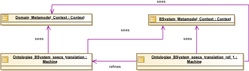
As we have chosen Event-B to express and verify the translation rules between the source and target metamodels, the first step is to specified them in Event-B. This also allows us to formally define the semantics of SysML/KAOS domain models. Figure 9 represents the structure of the whole Event-B specification. This specification can only be splitten into two abstraction levels because all the translation rules use the class LogicFormula, except those related to the class DomainModel. The first machine, Ontologies_BSystem_specs_translation, contains the rules for the translation of instances of DomainModel into instances of Component. The other rules are defined in the machine Ontologies_BSystem_specs_translation_ref_1. We have defined static elements of the target metamodel in a context named BSystem_Metamodel_Context and static elements of the source metamodel in the one named Domain_Metamodel_Context. The two machines have access to the definitions of the contexts. For the sake of concision, we provide only an illustrative excerpt of these Event-B specifications. For instance, the model Ontologies_BSystem_specs_translation_ref_1 contains more than a hundred variables, a hundred invariants and fifty events and it gives rise to a thousand proof obligations. The full version can be found in [24, 8].
For the translation of some metamodel elements, we have followed the rules proposed in [23, 22], such as : classes which are not subclasses give rise to abstract sets, each class gives rise to a variable typed as a subset and containing its instances and each association or property gives rise to a variable typed as a relation. For example, in the following specification, class DomainModel of the source metamodel and class Component of the target metamodel give rise to abstract sets representing all their possible instances. Variables are introduced and typed (inv0_1, inv0_2 and inv0_3) to represent sets of defined instances.
CONTEXT Domain_Metamodel_Context
SETS DomainModel_Set
END
CONTEXT BSystem_Metamodel_Context
SETS Component_Set
END
MACHINE Ontologies_BSystem_specs_translation
VARIABLES Component System Refinement
DomainModel
INVARIANT
inv0_1:
inv0_2:
inv0_3:
END
UML enumerations are represented as Event-B enumerated sets. For example, in the following specification, defined in BSystem_Metamodel_Context, class Operator of the target metamodel is represented as an enumerated set containing the constants Inclusion_OP, Belonging_OP and BecEq2Set_OP.
SETS Operator
CONSTANTS Inclusion_OP
Belonging_OP
BecEq2Set_OP
AXIOMS
axiom1:
Variables are also used to represent attributes and associations [23, 22] such as the attribute isVariable of the class Concept in the source metamodel (inv1_5) and the association definedIn between the classes Constant and Component in the target metamodel (inv1_7). To avoid ambiguity, we have prefixed and suffixed each element name with that of the class to which it is attached (e.g. Concept_isVariable or Constant_definedIn_Component). Furthermore, for a better readability of the specification, we have chosen to add "s" to the name of all Event-B relations for which an image is a set (e.g. Constant_isInvolvedIn_LogicFormulas or Invariant_involves_Variables).
MACHINE Ontologies_BSystem_specs_translation_ref_1
VARIABLES Concept_isVariable Constant_definedIn_Component Invariant_involves_Variables
Constant_isInvolvedIn_LogicFormulas
INVARIANT
inv1_5:
inv1_7:
inv1_11:
inv1_12:
inv1_13:
inv1_14:
END
An association r from a class A to a class B to which the ordered constraint is attached is represented as a variable r typed through the invariant . This is for example the case of the association Invariant_involves_Variables of the target metamodel (inv1_11). If instances of B have the same sequence number, then the invariant becomes . This is for example the case of the association Constant_isInvolvedIn_LogicFormulas of the target metamodel (inv1_13). Invariant inv1_12 ensures that each variable is involved in at least one invariant and inv1_14 ensures the same constraint for constants.
5.2 Event-B Specification of Translation Rules
The correspondence links between instances of a class A of the source metamodel and instances of a class B of the target metamodel are captured in a variable named A_corresp_B typed by the invariant . It is an injection because each instance, on both sides, must have at most one correspondence. The injection is partial because all the elements are not translated at the same time. Thus, it is possible that at an intermediate state of the system, there are elements not yet translated. For example, correspondence links between instances of Concept and instances of AbstractSet are captured as follows
INVARIANTS inv1_8:
Translation rules have been modeled as convergent events. Each event execution translates an element of the source into the target. Variants and event guards and type have been defined such that when the system reaches a state where no transition is possible (deadlock state), all translations are done. Up to fifty events have been specified. The rest of this section provides an overview of the specification of some of these events in order to illustrate the formalisation process and some of its benefits and difficulties. The full specification can be found in [24, 8].
5.2.1 Translating a Domain Model with Parent (line 2 of table LABEL:tableau_recapitulatif_correspondances)
The corresponding event is called domain_model_with_parent_to_component. It states that a domain model, associated with another one representing its parent, gives rise to a refinement component.
MACHINE Ontologies_BSystem_specs_translation
INVARIANT
inv0_6:
inv0_7:
Event domain_model_with_parent_to_component convergent
any DM PDM o_DM
where
grd0:
grd1:
grd2:
grd3:
grd4:
grd5:
grd6:
then
act1:
act1:
act1:
act1:
END
END
The refinement component must be the one refining the component corresponding to the parent domain model. Guard grd1 is the main guard of the event. It is used to ensure that the event will only handle instances of DomainModel with parent and only instances which have not yet been translated. It also guarantee that the event will be enabled until all these instances are translated. Action act3 states that o_DM refines the correspondent of PDM. To discharge, for this event, the proof obligation related to the invariant inv0_6, it is necessary to guarantee that, given a domain model m not translated yet, and its parent pm that has been translated into component o_pm, then o_pm has no refinement yet. The invariant inv0_7 then appears accordingly to encode this constraint.
5.2.2 Translating a Concept with Parent (line 4 of table LABEL:tableau_recapitulatif_correspondances)
This rule leads to two events : the first one for when the parent concept corresponds to an abstract set (the parent concept does not have a parent : line 3 of table LABEL:tableau_recapitulatif_correspondances) and the second one for when the parent concept corresponds to a constant (the parent concept has a parent : line 4 of table LABEL:tableau_recapitulatif_correspondances). Below is the specification of the first event333Some guards and actions have been removed for the sake of concision.
Event concept_with_parent_to_constant_1 convergent
any CO o_CO PCO o_lg o_PCO
where
grd1:
grd2:
grd3:
grd4:
grd5:
grd6:
grd7:
then
act1:
act2:
act3:
act4:
act5:
act6:
act7:
act8:
act9:
END
The rule asserts that any concept, associated with another one, with the parentConcept association, gives rise to a constant, typed as a subset of the B System element corresponding to the parent concept. We use an instance of LogicFormula, named o_lg, to capture this constraint linking the concept and its parent correspondents (o_CO and o_PCO). Guard grd2 constrains the parent correspondent to be an instance of AbstractSet. Guard grd4 ensures that the event will not be triggered until the translation of the domain model containing the definition of the concept. Action act3 ensures that o_CO is defined in the component corresponding to the domain model where CO is defined. Action act6 defines the operator used by o_lg. Because the parent concept corresponds to an abstract set, o_CO is the only constant involved in o_lg (act7); o_PCO, the second operand, is a set (act8). Finally, action act9 defines o_lg as the typing predicate of o_CO.
Example :
| SysML/KAOS domain model | B System specification |
|
concept pco
concept co parent concept pco |
SETS
CONSTANTS PROPERTIES co pco |
The specification of the second event (when the parent concept corresponds to a constant) is different from the specification of the first one in some points. The three least trivial differences appear at guard grd2 and at actions act7 and act8. Guard grd2 constrains the parent correspondent to be an instance of Constant : . Thus, the first and the second operands involved in o_lg are constants :
act7:
act8:
This approach to modeling logic formulas allows us to capture all the information conveyed by the predicate which can then be used to make inferences and semantic analysis. It is especially useful when we deal with rules to propagate changes made to a generated B System specification back to the domain model (ie, propagate changes made to the target into the source).
5.3 Event-B Specification of Back Propagation Rules
We have modeled back propagation rules as Event-B convergent events; each execution of an event propagates the addition of an element.
5.4 Addition of a Constant, Subset of the Correspondence of an Instance of Concept (line 5 of table LABEL:tableau_recapitulatif_correspondances)
This rule leads to two events: the first one is applied for a superset that is an abstract set and the second one for a superset that is a constant. Below is the specification of the first event.
Event constant_subset_concept_1 convergent
any CO b_CO PCO b_lg b_PCO
where
grd1:
grd2:
grd3:
grd4:
grd5:
grd6:
grd7:
grd8:
then
act1:
act2:
act3:
act4:
act5:
END
The rule asserts that in order to propagate the addition of a constant, we need to evaluate its typing predicate. When it is typed as a subset of the correspondence of an instance of Concept, then it gives rise to an instance of Concept. We use an instance of LogicFormula, named b_lg, to represent the typing predicate (grd2) of b_CO, defined with grd1. Guards grd3 and grd4 ensure that b_CO is typed as a subset. Guard grd5 ensures that the superset, b_PCO, is an abstract set corresponding to an instance of Concept. Guard grd6 constrains PCO to be the correspondence of b_PCO. CO, an instance of Concept, is then elicited and act2 defines b_CO as its correspondence. Finally, act4 defines PCO as its parent concept. Guard grd8 ensures that the event will be triggered only if the B System component, where b_CO is defined, corresponds to an existing domain model. Action act3 ensures that CO is defined in that domain model.
The specification of the second event (when the superset is a constant) is different from the specification of the first one in five points:
grd4:
grd5:
grd6:
grd7:
Guard grd4 constrains the superset, b_PCO, to be a constant involved in a logic formula. Guard grd5 ensures that b_PCO is involved as the second operand of b_lg. Finally, guards grd6 and grd7 constrain the domain model element corresponding to b_PCO.
5.5 Addition of a Variable, Subset of the Correspondence of an Instance of Concept (line 2 of table LABEL:tableau_recapitulatif_correspondances)
Like the previous rule, this rule leads to two events: the first one for when the superset is an abstract set and the second one for when the superset is a constant. Below is the most relevant part of the specification of the first event.
Event variable_subset_concept_1 convergent
any x_CO CO b_lg b_CO
where
grd1:
grd2:
grd3:
grd4:
grd5:
grd6:
grd7:
then
act1:
act2:
END
In order to propagate the addition of a variable, we need to evaluate its typing invariant. When it is typed as a subset of an abstract set, correspondence of an instance of Concept, then the isVariable property of the concept has to be set to TRUE.
5.6 Other Event-B Specifications of Back Propagation Rules
Addition of a new abstract set
- MACHINE
-
event_b_specs_from_ontologies_ref_1
- REFINES
-
event_b_specs_from_ontologies
- SEES
-
EventB_Metamodel_Context,Domain_Metamodel_Context
- Event
-
rule_101 ordinary
handling the addition of a new abstract set (correspondence to a concept)- any
-
-
CO
-
o_CO
-
- where
-
-
grd0:
-
grd1:
-
grd2:
-
grd3:
-
grd4:
-
- then
-
-
act1:
-
act2:
-
act3:
-
act4:
-
- end
- Event
-
rule_102 ordinary
handling the addition of a new abstract set (correspondence to a custom data set)- any
-
-
DS
-
o_DS
-
- where
-
-
grd0:
-
grd1:
-
grd2:
-
grd3:
-
grd4:
-
grd5:
-
- then
-
-
act1:
-
act2:
-
act3:
-
act4:
-
act5:
-
- end
- END
Addition of an enumerated set
- MACHINE
-
event_b_specs_from_ontologies_ref_1
- REFINES
-
event_b_specs_from_ontologies
- SEES
-
EventB_Metamodel_Context,Domain_Metamodel_Context
- Event
-
rule_103 ordinary
handling the addition of an enumerated set- any
-
-
EDS
-
o_EDS
-
elements
-
o_elements
-
mapping_elements_o_elements
-
- where
-
-
grd0:
-
grd1:
-
grd2:
-
grd3:
-
grd4:
-
grd5:
-
grd6:
-
grd7:
-
grd8:
-
grd9:
-
grd10:
-
grd11:
-
- then
-
-
act1:
-
act2:
-
act3:
-
act4:
-
act5:
-
act6:
-
act7:
-
act8:
-
act9:
-
act10:
-
- end
- END
Addition of a set item
- MACHINE
-
event_b_specs_from_ontologies_ref_1
- REFINES
-
event_b_specs_from_ontologies
- SEES
-
EventB_Metamodel_Context,Domain_Metamodel_Context
- Event
-
rule_104 ordinary
handling the addition of a new element in an existing enumerated set- any
-
-
EDS
-
o_EDS
-
element
-
o_element
-
- where
-
-
grd0:
-
grd1:
-
grd2:
-
grd3:
-
grd4:
-
grd5:
-
grd6:
-
- then
-
-
act1:
-
act2:
-
act3:
-
act4:
-
- end
- END
Addition of a constant, sub set of an instance of Concept (full)
- MACHINE
-
event_b_specs_from_ontologies_ref_1
- REFINES
-
event_b_specs_from_ontologies
- SEES
-
EventB_Metamodel_Context,Domain_Metamodel_Context
- Event
-
rule_105_1 ordinary
handling the addition of a constant, sub set of an instance of Concept (case where the concept corresponds to an abstract set)- any
-
-
CO
-
o_CO
-
PCO
-
o_lg
-
o_PCO
-
- where
-
-
grd0:
-
grd1:
-
grd2:
-
grd3:
-
grd4:
-
grd5:
-
grd6:
-
grd7:
-
grd8:
-
grd9:
-
grd10:
-
- then
-
-
act1:
-
act2:
-
act3:
-
act4:
-
act5:
-
- end
- Event
-
rule_105_2 ordinary
handling the addition of a constant, sub set of an instance of Concept (case where the concept corresponds to a constant)- any
-
-
CO
-
o_CO
-
PCO
-
o_lg
-
o_PCO
-
- where
-
-
grd0:
-
grd1:
-
grd2:
-
grd3:
-
grd4:
-
grd5:
-
grd6:
-
grd7:
-
grd8:
-
grd9:
-
grd10:
-
grd11:
-
- then
-
-
act1:
-
act2:
-
act3:
-
act4:
-
act5:
-
- end
- END
Addition of an individual
- MACHINE
-
event_b_specs_from_ontologies_ref_1
- REFINES
-
event_b_specs_from_ontologies
- SEES
-
EventB_Metamodel_Context,Domain_Metamodel_Context
- Event
-
rule_106_1 ordinary
handling the addition of an individual (case where the concept corresponds to an abstract set)- any
-
-
ind
-
o_ind
-
CO
-
o_lg
-
o_CO
-
- where
-
-
grd0:
-
grd1:
-
grd2:
-
grd3:
-
grd4:
-
grd5:
-
grd6:
-
grd7:
-
grd8:
-
grd9:
-
- then
-
-
act1:
-
act2:
-
act3:
-
- end
- Event
-
rule_106_2 ordinary
handling the addition of an individual (case where the concept corresponds to a constant)- any
-
-
ind
-
o_ind
-
CO
-
o_lg
-
o_CO
-
- where
-
-
grd0:
-
grd1:
-
grd2:
-
grd3:
-
grd4:
-
grd5:
-
grd6:
-
grd7:
-
grd8:
-
grd9:
-
grd10:
-
- then
-
-
act1:
-
act2:
-
act3:
-
- end
- END
Addition of a data value
- MACHINE
-
event_b_specs_from_ontologies_ref_1
- REFINES
-
event_b_specs_from_ontologies
- SEES
-
EventB_Metamodel_Context,Domain_Metamodel_Context
- Event
-
rule_107 ordinary
handling the addition of a data value- any
-
-
dva
-
o_dva
-
DS
-
o_lg
-
o_DS
-
- where
-
-
grd0:
-
grd1:
-
grd2:
-
grd3:
-
grd4:
-
grd5:
-
grd6:
-
grd7:
-
grd8:
-
grd9:
-
- then
-
-
act1:
-
act2:
-
act3:
-
- end
- END
Addition of a variable, sub set of an instance of Concept (full)
- MACHINE
-
event_b_specs_from_ontologies_ref_1
- REFINES
-
event_b_specs_from_ontologies
- SEES
-
EventB_Metamodel_Context,Domain_Metamodel_Context
- Event
-
rule_108_1 ordinary
handling the addition of a variable, sub set of an instance of Concept (case where the concept corresponds to an abstract set)- any
-
-
x_CO
-
CO
-
o_lg
-
o_CO
-
- where
-
-
grd0:
-
grd1:
-
grd2:
-
grd3:
-
grd4:
-
grd5:
-
grd6:
-
grd7:
-
- then
-
-
act1:
-
act2:
-
- end
- Event
-
rule_108_2 ordinary
handling the addition of a variable, sub set of an instance of Concept (case where the concept corresponds to a constant)- any
-
-
x_CO
-
CO
-
o_lg
-
o_CO
-
- where
-
-
grd0:
-
grd1:
-
grd2:
-
grd3:
-
grd4:
-
grd5:
-
grd6:
-
grd7:
-
grd8:
-
- then
-
-
act1:
-
act2:
-
- end
- END
5.7 Discussion and Experience
The rules that we propose allow the automatic translation of domain properties, modeled as ontologies, to B System specifications, in order to fill the gap between the system textual description and the formal specification. It is thus possible to benefit from all the advantages of a high-level modeling approach within the framework of the formal specification of systems : decoupling between formal specification handling difficulties and system modeling; better reusability and readability of models; strong traceability between the system structure and stakeholder needs. Applying the approach on case studies [28] allowed us to quickly build the refinement hierarchy of the system and to determine and express the safety invariants, without having to manipulate the formal specifications. Furthermore, it allows us to limit our formal specification to the perimeter defined by the expressed needs. This step also allowed us to enrich the domain modeling language expressiveness.
Formally defining the SysML/KAOS domain modeling language, using Event-B, allowed us to completely fulfill the criteria for it to be an ontology modeling formalism [29]. Furthermore, formally defining the rules in Event-B and discharging the associated proof obligations allowed us to prove their consistency, to animate them using ProB and to reveal several constraints (guards and invariants) that were missing when designing the rules informally or when specifying the metamodels. For instance: (1) if an instance of Concept x, with parent px does not have a correspondent yet and if px does, then, the correspondent of px should not be refined by any instance of Component (inv0_7 defined inOntologies_BSystem_specs_translation and described in Sect. 5.2.1); (2) elements of an enumerated data set should have correspondents if and only if the enumerated data set does; (3) if a concept, given as the domain of an attribute (instance of Attribute), is variable, then the attribute must also be variable; the same constraint is needed for the domain and the range of a relation. In case of absence of this last constraint, it is possible to reach a state where an attribute maplet (instance of AttributeMaplet) is defined for a non-existing individual (because the individual has been dynamically removed). These constraints have been integrated in the SysML/KAOS domain modeling language in order to strengthen its semantics.
There are two essential properties that the specification of the rules must ensure and that we have proved using Rodin. The first one is that the rules are isomorphisms and it guarantees that established links between elements of the ontologies are preserved between the corresponding elements in the B System specification and vice versa. To do this, we have introduced, for each link between elements, an invariant guaranteeing the preservation of the corresponding link between the correspondences and we have discharged the associated proof obligations. This leads to fifty invariants. For example, to ensure that for each domain model pxx, parent of xx, the correspondent of xx refines the correspondent of pxx and vice versa, we have defined the following invariants:
inv0_8:
inv0_9:
The second essential property is to demonstrate that the system will always reach a state where all translations have been established. To automatically prove it, we have introduced, within each machine, a variant defined as the difference between the set of elements to be translated and the set of elements already translated. Then, each event representing a translation rule has been marked as convergent and we have discharged the proof obligations ensuring that each of them decreases the variant. For example, in the machine Ontologies_BSystem_specs_translation containing the definition of translation rules from domain models to B System components, the variant was defined as . Thus, at the end of system execution, we will have , which will reflect the fact that each domain model has been translated into a component.
There is no predefined type for ordered sets in Event-B.
This problem led us to the definition of composition of functions in order to define relations on ordered sets. Moreover, because of the size of our model (about one hundred invariants and about fifty events for each machine), we noted a rather significant performance reduction of Rodin during some operations such as the execution of auto-tactics or proof replay on undischarged proof obligations that have to be done after each update in order to discharge all previously discharged proofs.
Table 4 summarises the key characteristics of the Rodin project corresponding to the Event-B specification of metamodels and rules (translation and back propagation rules). The automatic provers seemed least comfortable with functions () and become almost useless when those operators are combined in definitions as for ordered associations ().
| Characteristics | Root level | First refinement level |
|---|---|---|
| Events | 3 | 50 |
| Invariants | 11 | 104 |
| Proof Obligations (PO) | 37 | 1123 |
| Automatically Discharged POs | 27 | 257 |
| Interactively Discharged POs | 10 | 866 |
6 Specification of the Hybrid ERTMS/ETCS Level 3 Standard
6.1 Main Characteristics of the Standard
The Hybrid ERTMS/ETCS level 3 protocol (HEEL3) has been proposed to optimize the use and occupation of railways [30, 31, 32].
It thus proposes the division of the track into separate entities, each named Trackside Train Detection (TTD).
In addition, each TTD is subdivided into sub-entities called Virtual Sub-Sections (VSS).
A TTD has two possible states: free and occupied with a safety invariant stating that if a train is located on a TTD, then the state of the TTD must be set to occupied.
In addition to these two states, a VSS may have the unknown or the ambiguous state.
The ambiguous state is used when the information available to the system suggest that two trains are potentially present on the VSS. The unknown state is used when the system can guarantee neither the presence nor the absence of a train on the VSS.
For an optimal safety, Movement Authorities (MA) are evaluated and assigned to each connected train.
The MA of a train designates a portion of the track on which it is guaranteed to move safely.
ERTMS (European Rail Traffic Management System)
designates a protocol and a set of tools that allow a train to know and report its position.
Similarly, TIMS (Train Integrity Monitoring System)
designates the component that allows a train to know and report its integrity and its size.
HEEL3
considers three train categories : those equipped with ERTMS and TIMS called INTEGER; those that are just equipped with a ERTMS which
allows them to broadcast their position (connected trains);
and finally, those that are equipped neither with a ERTMS nor with a TIMS called unconnected trains.
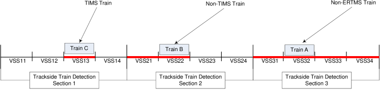
Figure 10 is an overview of the influence of the presence of ERTMS and TIMS on the track capacity exploitation [32]. A TIMS train (INTEGER) is considered to occupy a whole VSS. A non-TIMS train (connected train) is considered to occupy all the VSSs from its front to the end of the TTD section where it is located. Finally, a non-ERTMS train (unconnected train) is considered to occupy the whole TTD section where the system guess it is.
6.2 The Goal Diagram
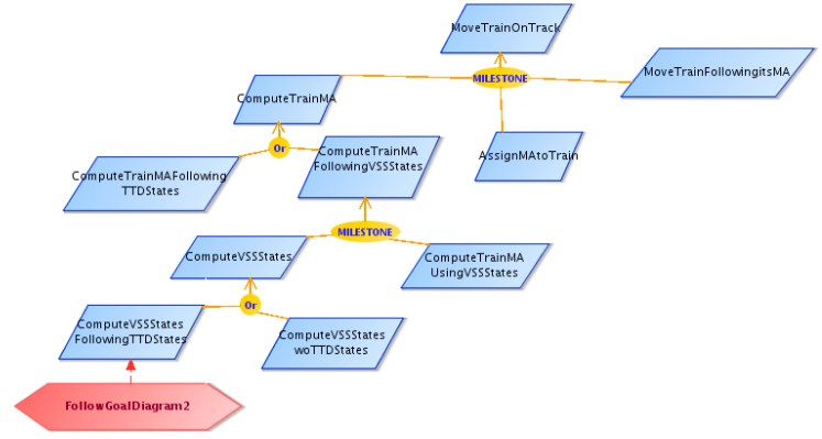
The SysML/KAOS requirements engineering method allows the progressive construction of system requirements from refinements of stakeholder needs. Thus, even if the management of VSSs is the purpose of the case study, we need to put it into perspective with more abstract objectives that will explain what VSSs are useful for. Figure 11 is an excerpt from the SysML/KAOS functional goal diagram focused on the main system purpose : move trains on the track (MoveTrainOnTrack). To achieve it, the system must ensures that the train has a valid MA (ComputeTrainMA). If the MA has been recomputed, then the system must assign the new MA to the train (AssignMAtoTrain). Finally, the train has to move following its assigned MA (MoveTrainFollowingItsMA). The second refinement level of the SysML/KAOS goal diagram focuses on the informations needed to determine the MA of a train : the MA computation can be based only on TTD states (ComputeTrainMAFollowingTTDStates) or following VSS states (ComputeTrainMAFollowingVSSStates) [31]. When the computation is only based on TTD states, it corresponds to the ERTMS/ETCS Level 2 protocol. When VSS states are involved, it corresponds to the ERTMS/ETCS Level 3 protocol. The MA computation based on VSS states requires the update of the states of VSSs (ComputeVSSStates) and the computation of the MA (ComputeTrainMAUsingVSSStates). Finally, depending on the type of the ERTMS/ETCS level 3 implementation, it is possible to use or not the TTD states when computing the VSS states (table 1 of [32]). If TTD states are not required (virtual (without train detection) level 3 type), it corresponds to ComputeVSSStateswoTTDStates, with the disadvantage of only allowing the circulation of trains equipped with TIMS. If TTD states are used (hybrid level 3 type), it corresponds to ComputeVSSStatesFollowingTTDStates.
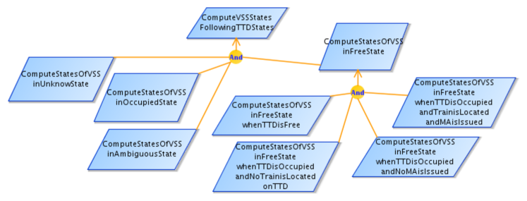
Figure 12 is an excerpt from the SysML/KAOS functional goal diagram focused on the purpose of VSS state computation with the use of TTD states (ComputeVSSStatesFollowingTTDStates). The computation of the current VSS states can be splitted into the determination of the current states of VSSs previously in the unknown state (ComputeStatesOfVSSinUnknownState), in the occupied state (ComputeStatesOfVSSinOccupiedState), in the ambiguous state (ComputeStatesOfVSSinAmbiguousState) and in the free state (ComputeStatesOfVSSinFreeState) (Figure 7 of [31]). The last refinement level is focused on VSSs previously in the free state. Its goals come from the requirements of the transition #1A of Table 2 of [31]. When the TTD is free, then the VSSs remain free (ComputeStatesOfVSSinFreeStateWhenTTDisFree). When the TTD is occupied and no train is located on it or no MA is issued, then the VSSs move in the unknown state (ComputeStatesOfVSSinFreeStateWhenTTDisOccupiedandNoTrainisLocatedonTTD, ComputeStatesOfVSSinFreeStateWhenTTDisOccupiedandNoMAisIssued). The other transitions are the purpose of ComputeStatesOfVSSinFreeStateWhenTTDisOccupiedandTrainisLocatedandMAisIssued.
The rest of this section consists of a presentation of the SysML/KAOS domain models associated with the most relevant refinement levels of the goal diagrams and of a description of the B System specifications obtained from goals and ontologies. From the goal model, we distinguish seven refinement levels which are translated into seven B System components. The formal specification has been verified using Rodin [33], an industrial-strength tool supporting the Event-B method [5]. We have in particular discharged all the proof obligations associated with the safety invariants that we have identified and with the SysML/KAOS refinement operators that appear in the goal diagram. For the sake of concision, we will present here only the first three refinement levels. The full specification can be found in [34].
6.3 The Root Level
Figure 13 represents the domain model associated with the root level of the SysML/KAOS goal diagram of Figure 11. The concept TRAIN models the set of trains. The attribute connectedTrain models the subset of TRAIN that broadcast their location at least once and for each, the current connection status. The attribute front models the estimated position of the front of each connected train. For each connected train equipped with a TIMS, the attribute rear models the estimated position of its rear444 the rear is deduced from the front and length of the train, since a train equipped with a TIMS broadcast its length and its integrity. Thus, represents the set of trains equipped with a ERTMS and not equipped with a TIMS. Predicates represent constraints on domain model elements. Each predicate is prefixed with an identifier. For example, the predicate p0.2 defines TRACK as the data range .
SYSTEM ertms_etcs_case_study
SETS TRAIN
CONSTANTS a b TRACK
PROPERTIES
axm1: axm2: p0.1:
p0.2:
VARIABLES connectedTrain front rear
INVARIANT
inv1:
inv2:
inv3:
p0.3:
Event MoveTrainOnTrack
any tr len
where
grd1:
grd2:
grd3:
then
act1:
act2:
END
END
Figure 14 represents the B System model obtained from the translation of the root level of the goal diagram of Figure 11 and of the associated domain model of Figure 13. The domain model gives rise to sets, constants, properties, variables and invariants of the formal specification. Predicates involving variables give rise to invariants and the others to properties. The isFunctional and isTotal characteristics of attributes, are used to guess if an attribute should be translated into a partial or total function. The root goal is translated into an event for which the body has been manually specified: the movement of a connected train (grd1) results in the incrementation of the position of its front (act1) and its rear (act2 in the case of an INTEGER train) of the value corresponding to the movement. Of course, the movement can only be done if the train stays on the track (grd3).
6.4 The First Refinement Level
Figure 15 represents the domain model associated with the first refinement level of the SysML/KAOS goal diagram of Figure 11. It refines the one associated with the root level and introduces an attribute named MA representing the MA assigned to a connected train. The MA of a train is modeled as a contiguous part of the track (p1.1), containing the train (p1.2 and p1.3). Finally, the predicate p1.4 asserts that the MA assigned to two different trains must be disjoint. The predicates p1.2 and p1.3 are gluing invariants, linking the concrete variable MA with the abstract variables front and rear.
REFINEMENT ertms_etcs_case_study_ref_1
REFINES ertms_etcs_case_study
VARIABLES connectedTrain front rear MA MAtemp
INVARIANT
inv1:
p1.1:
p1.2:
p1.3:
p1.4:
inv6:
inv7:
theorem s1:
theorem s2:
theorem s3:
theorem s4:
Event
ComputeTrainMA
any tr p q len
where
grd1:
grd2:
grd3:
grd4:
grd5:
grd6:
grd7:
then
act1:
END
AssignMAtoTrain
any tr len
where
grd1:
• • •
grd6:
then
act1:
END
MoveTrainFollowingItsMA
any tr len
where
grd1:
grd2:
grd3:
then
act1:
act2:
END
END
Figure 16 represents the B System model obtained from the translation of the first refinement level of the goal diagram of Figure 11 and of the associated domain model of Figure 15.
Each refinement level goal is translated into an event for which the body has been manually specified : the current MA of the train is computed and stored into a variable named MAtemp (event ComputeTrainMA). Because the computation of the MA is out of the scope of the case study [30], the event simply nondeterministically choose an MA, with respect to the safety invariants. This MA is then assigned to the train by updating the variable MA (event AssignMAtoTrain) and taken into account for the train displacement (event MoveTrainFollowingItsMA).
Theorems s1, s2, s3 and s4 represent the proof obligations related to the usage of the MILESTONE operator between the root and the first refinement levels.
Since each proof obligation has been modeled as an Event-B theorem, it has been proved based on system properties and invariants.
To deal with the fact that Event-B does not currently support the temporal logic, we have used the proof obligation for the invariants s2 and s3, instead of (Sect. 1.3), since .
The full specification of s1 is given below:
theorem s1:
It expresses the fact that the activation of the guard of ComputeTrainMA for certain parameters is sufficient for the activation of the guard of MoveTrainOnTrack for this same group of parameters.
6.5 The Second Refinement Level
Figure 17 represents the domain model associated with the second refinement level of the diagram of Figure 11. It refines the one associated with the first refinement level and introduces two concepts named TTD and VSS. The attributes stateTTD and stateVSS represent the states of the corresponding concepts. The predicates p2.1..p2.8 define each TTD as a contiguous part of the track and each VSS as a contiguous part of a TTD. The predicates p2.9 and p2.10 are used to state that if a train is located on a TTD, then its state must be occupied: a train is located on if (p2.9) or if tr is equipped with a TIMS () and (p2.10). Finally, the predicates p2.11..p2.13 states that two different trains must be in disjoint parts of the track: for two trains tr1 and tr2, if they are equipped with TIMS, then the track portions that they occupy should just be disjointed (p2.11); if they are on the same TTD and one of them, ( tr2), is not equipped with a TIMS, then, the second, ( tr1), must be equipped with a TIMS and tr2 must be in the rear of tr1 (p2.12); if none of them is an INTEGER train, then they must be in two distincts TTDs (p2.13). The predicates p2.9 and p2.10 are gluing invariants, linking the concrete variable stateTTD with the abstract variables front and rear. The B System specification raised from the translation of the second refinement level includes the result of the translation of the domain model of Figure 17, two new events (ComputeTrainMAFollowingTTDStates, ComputeTrainMAFollowingVSSStates), an extension of the event MoveTrainFollowingItsMA taking into account the new safety invariants and the theorems representing the proof obligations related to the usage of the OR operator between the first and second refinement levels. The specification below (Figure 18) represents the new definition of MoveTrainFollowingItsMA and the theorems related to the refinement operator. The parameter ttds is introduced to capture the TTD requiring an update of their states because of the train movement (grd4, grd5 and act3). Guards grd6..grd9 ensure that the train movement will not lead to the violation of the safety invariants p2.11..p2.13 : grd6 stands for p2.11; grd7 and grd8 stand for p2.12; grd9 stands for p2.13.
REFINEMENT ertms_etcs_case_study_ref_2
REFINES ertms_etcs_case_study_ref_1
INVARIANT
theorem s1:
theorem s2:
theorem s3:
theorem s4:
theorem s5:
theorem s6:
Event MoveTrainFollowingItsMA
any tr len ttds
where
grd1:
grd2:
grd3:
grd4:
grd5:
grd6:
grd7:
grd8:
grd9:
then
act1:
act2:
act3:
END
END
6.6 The Fifth Refinement Level
For the fifth refinement level, corresponding to the first refinement level of the goal diagram of Figure 12, the B System specification introduces four events raised from the translation of the goals and five theorems representing the proof obligations related to the usage of the AND operator between the fourth and the fifth refinement levels. These theorems are :
theorem s1:
theorem s2:
theorem s3:
theorem s4:
theorem s5:
6.7 Discussion
This case study allowed us to benefit from the advantages of a high-level modeling approach within the framework of the formal specification of the hybrid ERTMS/ETCS level 3 requirements : decoupling between formal specification handling difficulties and system modeling; better reusability and readability of models; strong traceability between the system formal specification and the goal model, which is an abstraction of the case study description. Using the SysML/KAOS method, we have quickly build the refinement hierarchy of the system and we have determined and formally expressed the safety invariants. The approach bridges the gap between the system textual description and its formal specification. Its use has made it possible to better present the specifications, excluding predicates, to stakeholders and to better delineate the system boundaries. Using Rodin [33], we have formally verified and validated the safety invariants and the goal diagram refinement hierarchy. Through proB, we have animated the formal model. The full specification can be found in [34]. One conclusion of our work is that the description of the standard, as it exists in the documents [30, 31, 32], does not guarantee the absence of train collisions. Indeed, since the standard allows the movement of unconnected trains on the track, nothing is specified to guarantee that an unconnected train will not hit another train (connected or not). The animation of the specification allows the observation of these states. The only guarantee that the safety invariants expressed in [30, 31, 32] bring is that a connected train will never hit another train.
We have also specified in a companion paper [35] the case study using plain Event-B, in the traditional style. Two distinct specifiers (first author of [35] and first author of this paper) wrote each specification without interacting with each other during specification construction. Critical reviewing by the team was then conducted after the specifications were built. The specification in [35] includes four refinement levels. The TTDs and trains are introduced in the root level and the VSSs are introduced in the second refinement level, as refinements of TTDs. The MAs and VSS states are introduced in the third refinement level (M3), for train movement supervision. A strategy is proposed to prove the determinism of the transitions of VSS states. The state variables of [35] are partitioned into environment variables and controller variables, and similarly for events. Environment events only modify environment variables. Controller events read environment variables and update controller variables. In this paper, we only model controller events; state variables represent the controller view of the environment. The execution ordering and the refinement strategy are enforced using proof obligations expressed as theorems, whereas in [35] there is no proof about these aspects. In [35], the safety properties are introduced in the last refinement level; here, we introduce them in the first (predicate p1.4) and second (predicates p2.9..p2.13) refinements. In [35], all trains equipped with ERTMS are equipped with TIMS, so they broadcast their front and rear; here, we consider ERTMS trains with or without TIMS, so a ERTMS train may or may not broadcast its rear. The SysML/KAOS method makes it possible to trace the source and justify the need for each formal component and its contents, in relation with the SysML/KAOS goal and domain models.
The expression of theorems representing proof obligations associated to SysML/KAOS refinement operators was difficult because there is no way in Rodin to designate the guard and the post condition of an event within predicates. Table 4 summarises the key characteristics related to the formal specification. It seemed that the provers have a lot of trouble with data ranges such as and with conditional actions such as defined in the component ertms_etcs_case_study to simulate an if-then-else in order to avoid the definition of a second event.
| Refinement level | L0 | L1 | L2 | L3 | L4 | L5 | L6 |
| Invariants | 4 | 11 | 13 | 4 | 6 | 5 | 9 |
| Proof Obligations (PO) | 20 | 40 | 50 | 13 | 5 | 5 | 14 |
| Automatically Discharged POs | 17 | 30 | 30 | 11 | 0 | 0 | 4 |
| Interactively Discharged POs | 3 | 5 | 20 | 2 | 5 | 5 | 10 |
Acknowledgment
This work is carried out within the framework of the FORMOSE project [6] funded by the French National Research Agency (ANR). It is also partly supported by the Natural Sciences and Engineering Research Council of Canada (NSERC).
References
- [1] A. van Lamsweerde, Requirements Engineering - From System Goals to UML Models to Software Specifications. Wiley, 2009.
- [2] C. Gnaho and F. Semmak, “Une extension SysML pour l’ingénierie des exigences dirigée par les buts,” in 28e Congrès INFORSID, France, 2010, pp. 277–292.
- [3] A. Mammar and R. Laleau, “On the use of domain and system knowledge modeling in goal-based Event-B specifications,” in ISoLA 2016, Lecture Notes in Computer Science. Springer, pp. 325–339.
- [4] F. Boniol and V. Wiels, “The landing gear system case study,” ser. ABZ. Springer, 2014.
- [5] J. Abrial, Modeling in Event-B - System and Software Engineering. Cambridge University Press, 2010.
- [6] ANR-14-CE28-0009, “Formose ANR project,” 2017. [Online]. Available: http://formose.lacl.fr/
- [7] ClearSy, “Atelier B: B System,” 2014. [Online]. Available: http://clearsy.com/
- [8] S. Tueno, R. Laleau, A. Mammar, and M. Frappier, “Formal Representation of SysML/KAOS Domain Models ,” ArXiv e-prints, cs.SE, 1712.07406, Dec. 2017. [Online]. Available: https://arxiv.org/pdf/1712.07406.pdf
- [9] A. Matoussi, F. Gervais, and R. Laleau, “A goal-based approach to guide the design of an abstract Event-B specification,” in ICECCS 2011. IEEE Computer Society, pp. 139–148.
- [10] S. Tueno, R. Laleau, A. Mammar, and M. Frappier, “The SysML/KAOS Domain Modeling Approach,” ArXiv e-prints, cs.SE, 1710.00903, Sep. 2017. [Online]. Available: https://arxiv.org/pdf/1710.00903.pdf
- [11] ——, “Towards using ontologies for domain modeling within the sysml/kaos approach,” in IEEE 25th International Requirements Engineering Conference Workshops, RE 2017 Workshops, Lisbon, Portugal, September 4-8, 2017. IEEE Computer Society, 2017, pp. 1–5. [Online]. Available: https://doi.org/10.1109/REW.2017.22
- [12] K. Sengupta and P. Hitzler, “Web ontology language (OWL),” in Encyclopedia of Social Network Analysis and Mining, 2014, pp. 2374–2378.
- [13] G. Pierra, “The PLIB ontology-based approach to data integration,” in IFIP 18th World Computer Congress, ser. IFIP, vol. 156. Kluwer/Springer, 2004, pp. 13–18.
- [14] I. UL, “Owlgred home,” 2017. [Online]. Available: http://owlgred.lumii.lv/
- [15] H. H. Wang, D. Damljanovic, and J. Sun, “Enhanced semantic access to formal software models,” in Formal Methods and Software Engineering - ICFEM, Lecture Notes in Computer Science, vol. 6447. Springer, 2010, pp. 237–252.
- [16] E. Doberkat, “The Object-Z specification language,” Softwaretechnik-Trends, vol. 21, no. 1, 2001.
- [17] J. S. Dong, J. Sun, and H. H. Wang, “Z approach to semantic web,” in Formal Methods and Software Engineering - ICFEM, Lecture Notes in Computer Science, vol. 2495. Springer, 2002, pp. 156–167.
- [18] F. van Harmelen, P. F. Patel-Schneider, and I. Horrocks, “Reference description of the DAML+ OIL ontology markup language,” 2001.
- [19] I. Poernomo and T. Umarov, “A mapping from normative requirements to Event-B to facilitate verified data-centric business process management,” ser. CEE-SET Lecture Notes in Computer Science, vol. 7054. Springer, 2009, pp. 136–149.
- [20] E. Alkhammash, M. J. Butler, A. S. Fathabadi, and C. Cîrstea, “Building traceable Event-B models from requirements,” Sci. Comput. Program., vol. 111, pp. 318–338, 2015.
- [21] Alkhammash, Eman H., “Derivation of Event-B Models from OWL Ontologies,” MATEC Web Conf., vol. 76, p. 04008, 2016.
- [22] C. Snook and M. Butler, “UML-B: Formal Modeling and Design Aided by UML,” ACM Trans. Softw. Eng. Methodol., vol. 15, no. 1, pp. 92–122, Jan. 2006.
- [23] R. Laleau and A. Mammar, “An overview of a method and its support tool for generating B specifications from UML notations.” The Fifteenth IEEE International Conference on Automated Software Engineering, ASE 2000, 2000, pp. 269–272.
- [24] S. Tueno, R. Laleau, A. Mammar, and M. Frappier, “Event-B Specification of Translation Rules,” 2017. [Online]. Available: https://github.com/stuenofotso/SysML_KAOS_Domain_Model_Parser/tree/master/SysMLKAOSDomainModelRules
- [25] ——, “SysML/KAOS Domain Modeling Tool,” 2017. [Online]. Available: https://github.com/stuenofotso/SysML_KAOS_Domain_Model_Parser
- [26] Jetbrains, “Jetbrains mps,” 2017. [Online]. Available: https://www.jetbrains.com/mps/
- [27] S. Tueno, M. Frappier, R. Laleau, and A. Mammar, “Modeling the Hybrid ERTMS/ETCS Level 3 Standard Using a Formal Requirements Engineering Approach,” Springer proceedings of 6th International ABZ Conference, 2018.
- [28] S. Tueno, R. Laleau, A. Mammar, and M. Frappier, “The SysML/KAOS Domain Modeling Language (Tool and Case Studies),” 2018. [Online]. Available: https://github.com/stuenofotso/SysML_KAOS_Domain_Model_Parser/tree/master
- [29] Y. A. Ameur, M. Baron, L. Bellatreche, S. Jean, and E. Sardet, “Ontologies in engineering: the OntoDB/OntoQL platform,” Soft Comput., vol. 21, no. 2, pp. 369–389, 2017.
- [30] T. S. Hoang, M. Butler, and K. Reichl, “The Hybrid ERTMS/ETCS Level 3 Case Study,” ABZ, pp. 1–3, 2018. [Online]. Available: https://github.com/stuenofotso/SysML_KAOS_Domain_Model_Parser/blob/master/ABZ18_ERTMS/ERTMS_L3_Hybrid.pdf
- [31] EEIG ERTMS Users Group, “Hybrid ERTMS/ETCS Level 3: Principles,” Ref. 16E042 Version 1A, Jul. 2017.
- [32] F. Nicola, v. H. Henri, A. Laura, and B. Maarten, “ERTMS Level 3: the Game-Changer,” IRSE News View, p. 232, Apr. 2017.
- [33] M. J. Butler, C. B. Jones, A. Romanovsky, and E. Troubitsyna, Eds., Rigorous Development of Complex Fault-Tolerant Systems, ser. Lecture Notes in Computer Science, vol. 4157. Springer, 2006.
- [34] S. Tueno, R. Laleau, A. Mammar, and M. Frappier, “SysML/KAOS Approach on the Hybrid ERTMS/ETCS Level 3 case study,” 2018. [Online]. Available: https://github.com/stuenofotso/SysML_KAOS_Domain_Model_Parser/tree/master/ABZ18_ERTMS
- [35] A. Mammar, M. Frappier, S. Tueno, and R. Laleau, “An Event-B Model of the Hybrid ERTMS/ETCS Level 3 Standard,” Springer proceedings of 6th International ABZ Conference ASM, Alloy, B, TLA, VDM, Z, 2018.