Searching for Lepton Flavour Violation with the Mu3e Experiment
Abstract:
The upcoming Mu3e experiment searches for the lepton flavour
violating decay with the aim of a final sensitivity of one signal
decay in observed muon decays, an improvement over the preceding
SINDRUM experiment by four orders of magnitude. In the first phase, the
experiment will be operated at an existing intense muon beam line at the
Paul Scherrer Institute. With muon stopping rates of about
, a single-event sensitivity of can
be achieved. For the ultimate sensitivity, a new high intensity muon beam
line is required.
In order to suppress background, the tracking detector is designed to
measure low momentum electron and positron tracks with excellent precision
by making use of very thin silicon pixel sensors. In addition, scintillating
fibres and tiles provide precise timing information.
Currently, the collaboration is finalizing the detector design and preparing
for construction and commissioning.
1 Introduction
In the Standard Model of particle physics, lepton flavour is conserved. Yet
with the observation of neutrino oscillations, it became evident that nature
does not conserve lepton flavour, although an observation of lepton
flavour violation for charged leptons is still missing.
Extending the Standard Model to include neutrino mixing, lepton flavour
violating muon decays for example are mediated in loop-diagrams (see
figure 1a). With branching fractions of below
, these decays are far beyond experimental reach. Hence,
any observation of charged lepton flavour violation would be a clear sign for
physics beyond the Standard Model.
One channel to search for such phenomena is . It can be mediated for
instance in loop diagrams with super-symmetric particles (see
figure 1b), or at tree-level for example via a Z′ (see
figure 1c). The current limit set by the SINDRUM experiment
is at at confidence
level [1].
The upcoming Mu3e experiment plans for a sensitivity of about one signal event
in muon decays in the first phase of the experiment, and ultimately
one in muon decays in the second phase, thus improving on the
existing limit by four orders of magnitude [2].


2 Signal and Background
The signature of the signal decay is defined by two positrons and one
electron that emerge from a common vertex and appear coincidently in time. As muon
decays at rest are observed, the energies of the three decay particles sum up
to the muon rest mass and the sum of the momenta vanishes.
There are two types of background to searches. One is combinatorial
background arising from the observation of positrons and electrons from
multiple muon decays at a time, e. g. from the dominant Michel decay of the
muon in combination with an electron-positron pair from Bhabha scattering or
photon conversion. This background can be suppressed via constraints on the
relative timing of the particles, the vertex and momentum.
Another type is irreducible background via the radiative muon decay with
internal conversion . It can be distinguished from the
signal decay only by the missing energy resulting from the undetected pair of
neutrinos. Thus, the momentum resolution of the detector ultimately limits the
sensitivity of the experiment.
3 The Mu3e Experiment
The aimed at sensitivity level defines the demands on the Mu3e experiment. On the one hand, a large number of muon decays needs to be observed. This requires not only a high muon stopping rate but also a detector and data acquisition that is capable to cope with such high rates. On the other hand, a very good vertex and time resolution and an excellent momentum resolution are required in order to operate free of background.
3.1 Muon Beam
The Paul Scherrer Institute hosts the world’s most intense proton
beam. Secondary continuous muon beams are produced by the protons impinging on
a carbon target.
Mu3e will be located at the E5 beamline where subsurface muons of
are available.
The same beamline is also used by the MEGII experiment.
The compact muon beam line (CMBL), that is already installed in the
experimental area of Mu3e, allows to operate both experiments alternately.
Measurements at the CMBL have shown that the required rates of
can be provided.
The Paul Scherrer Institute is currently investigating on the high intensity
muon beamline with the aim to provide even higher muon beam rates. This would
enable Mu3e to reach the final sensitivity goal in phase II.
3.2 Detector Concept
The geometry of the Mu3e detector is optimized for precise momentum
measurements of the decay electrons and positrons. With a low momentum of
maximally , the momentum resolution is
dominated by multiple Coulomb scattering. Therefore, the material amount in
the active detector volume needs to be kept at a minimum.
The momentum is
measured via the bending radius of the particles in a magnetic field. Hence,
the momentum resolution improves with the lever arm between two position
measurements. The optimum momentum resolution is achieved after about a half
turn because at this point uncertainties caused by multiple scattering cancel
to first order. For this reason, the Mu3e experiment relies on measuring
recurling tracks.
When a particle has passed the outer detector layer, it will not cross further
material and following a helical trajectory it will eventually hit the outer
layers again. Between those two measurements, it has performed about a half
turn.
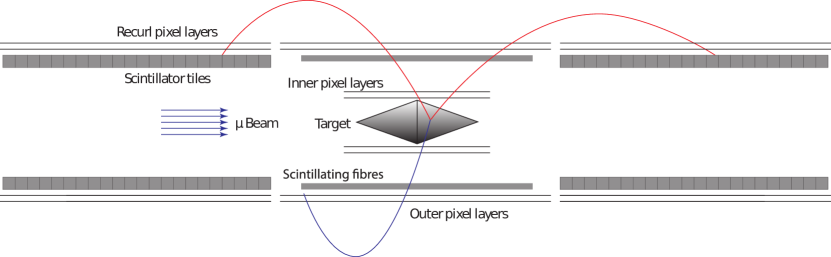
The geometry of the Mu3e detector is shown in figure 2. It
has the shape of an elongated tube and is placed in a solenoidal magnetic
field of .
In order to increase the acceptance for recurling tracks, so-called recurl
stations are installed both upstream and downstream of the central detector
part.
The incoming muons are stopped on a hollow double
cone target made of Mylar foil. The shape is chosen to
spread the muon decays over a large surface.
The detector consists of a
tracking detector made from thin silicon pixel sensors and a timing detector
system built from scintillating fibres and tiles.
The thinner fibres are placed in the central detector, the thicker tiles in
the recurl stations as at this point the material amount is no longer crucial.
The detector has a total length of about
and a diameter of .
3.2.1 Pixel Tracking Detector
For the tracking detector, pixel sensors are chosen as these comprise not only
an efficient and precise tracking but can also be produced very thin in the
particular technology chosen for Mu3e.
The target is surrounded by two layers of pixels sensors which allows for a
precise determination of the decay vertex. Two more layers of pixel sensors
are placed at a larger radius enabling the momentum measurement.
The recurl stations are equipped as well with a double-layer of pixel sensors
with the same radii as the outer pixel layers in the central station.
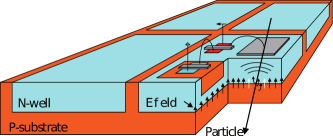
Mu3e deploys High Voltage Monolithic Active Pixel Sensors [3]. The individual pixels are implemented as deep N-wells in a p-doped substrate (see figure 3). By applying a reverse bias voltage of about , a depletion zone of to is formed. The electric field in the depletion zone is strong, so that charge carriers created by traversing ionising radiation can be collected via drift. As particle detection is limited to a thin volume close to the surface of the sensor, these sensors can be made very thin. For the final chip, a thickness of is envisaged.
Furthermore, it is possible to implement transistors within the
pixel and thus build readout electronics directly on the sensor chip. Signal
amplification and shaping is performed in the pixel itself, whereas the
digitisation happens in the periphery, a small part at the bottom edge of the
sensor. The sensor has digital, zero-suppressed data output at a fast serial
link of .
For the final chip, a pixel size of is
planned with an active area of per sensor.
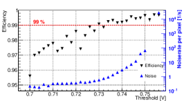
The development of the sensors is currently in the prototyping stage. The
MuPix7 prototype has an active area of
with a pixel size of
. Despite the small size, this prototype
comprises already all the functionalities required in the final chip. The
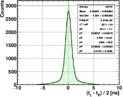
MuPix7 has been extensively tested with test beam, yielding for instance an
efficiency well above and a timing resolution smaller
than [4] (see
figure 4). Prototypes with a thickness of
are fully functional and perform equally well as
thicker prototypes.
The latest prototype MuPix8 is the first large scale MuPix sensor with an
active area of and a pixel size of
.
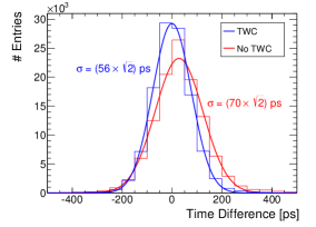
In order to improve the timing resolution,
the MuPix8 incorporates signal amplitude measurements allowing to correct for
time-walk.
The MuPix8 has been submitted on two different substrates: One with a
resistivity of , the same as in the case of MuPix7, and one
with a higher resistivity of . With the higher
resistivity, the signal becomes twice as large, and thus the signal to noise
ratio potentially improves.
The characterisation of MuPix8 has just started. First measurements have
shown that the chip is operational and indicate an overall good performance.
A further prototype, MuPix9, has recently been submitted. It is a small scale
prototype comprising circuitries for slow control that
have not yet been implemented in previous prototypes.
In addition, a novel serial-powering scheme is investigated.
The pixel sensors produce heat with a power of about
and thus need to be cooled. In
order not to add too much material to the detector, this is performed with a
flow of gaseous helium, both globally in the whole detector volume but also
locally through channels integrated in the mechanical support of the pixel
sensors. Finite element simulations predict feasible temperature gradients of
about .
The simulation results are verified in tests with a thermal mock-up of the
detector.
Although high flow velocities of are applied
locally, measurements have proven that
flow-induced vibrations stay below and will thus not
affect the track measurements.
3.2.2 Scintillating Timing Detector
The combinatorial background can be efficiently suppressed by timing
measurements. In the central detector part, a thin timing detector made of
three layers of scintillating fibres is placed directly underneath the outer
pixel layers. Likewise, the recurl stations are equipped with scintillating
tiles. With the combination of timing information from the fibre and
tile detector, suppression factors of about 100 for backgrounds with two
correlated and one uncorrelated track can be achieved. Backgrounds with three
uncorrelated tracks are even stronger suppressed.
The scintillation photons of the fibres are collected at both ends with a
silicon photo-multiplier (SiPM) column array as used by the LHCb
experiment [5]. Currently, fibres with round and
square cross sections are under investigation, and both fulfill the
requirements for the use in Mu3e.
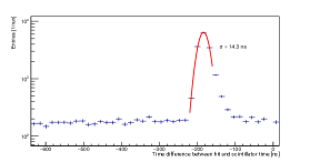
For example, a fibre prototype consisting of three layers of square multiclad
fibres achieves timing resolutions of with an
efficiency above (see figure 5).
Each of the scintillating tiles in the recurl stations has an individual
SiPM. In both detector systems, the SiPMs are read out with an custom-designed
time-to-digital converter ASIC called MuTRiG [6].
In the case of the tile detector, the MuTRiG operates in a two-threshold mode
which allows for time-walk compensation.
Prototypes of the tile detector yield time resolutions of without and with time walk correction at an efficiency of .
4 Sensitivity Studies
The sensitivity of Mu3e to the decay is estimated using a detailed
Geant4 simulation of the detector.
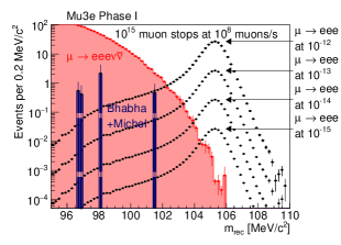
In figure 6a, the reconstructed mass of the three
electron-system is shown for the potential signal decay at various branching
fractions as well as for background from internal conversion decays and
combinatorial background. The combinatorial background is here represented by
the dominant contribution of Michel decays in combination with a Bhabha
scattering event in which a positron transfers enough momentum to an electron
such that the electron tracks is also visible in the detector.
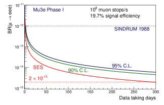
With an expected run time of 300 days of data taking in phase I at a muon
stopping rate of , the expected single-event
sensitivity is found to be , corresponding to a branching fraction
limit of at confidence level (see
figure 6b).
5 Status
Prototypes of the various subdetectors have successfully proven the
suitability of the chosen technologies for the usage in the Mu3e
experiment. The outcome of the studies of MuPix8 and MuPix9 for instance will
pave the way to the final pixel sensor chip.
The collaboration is currently finalizing the detector design and preparing
for construction and commissioning of the experiment. Commissioning is
foreseen for 2019 with potential first physics data taking in 2020.
In the first phase of Mu3e, a single event sensitivity of is
expected which poses a significant improvement on the limit to decays
with respect to previous experiments. The final sensitivity of Mu3e will be
reached in a second phase which is planned to be an upgrade of the phase I
detector. The envisaged single event sensitivity of is however
only feasible when muon stopping rates of about
become available.
Acknowledgments.
The author acknowledges support by the Research Training Group ‘Particle Physics beyond the Standard Model’ (GRK 1940) of the Deutsche Forschungsgemeinschaft.References
- [1] U.Bellgardt et al., Search for the Decay , Nucl.Phys. B299 (1988) 1-6
- [2] A.Blondel et al., Research Proposal for an Experiment to Search for the Decay , (2013) [physics.ins-det/1301.6113]
- [3] I.Perić, A novel monolithic pixelated particle detector implemented in high-voltage CMOS technology, in proceedings of NSS/MIC 2007, Nucl.Instrum.Meth. A582 (2007) 876
- [4] H.Augustin et al., The MuPix System-on-Chip for the Mu3e Experiment, in proceedings of VCI 2016, Nucl. Instrum. Meth. A845 (2017) 194-198 [physics.ins-det/1603.08751]
- [5] LHCb Collaboration, LHCb Tracker Upgrade Technical Design Report, CERN-LHCC-2014-001 LHCB-TDR-015 (2014)
- [6] H.Chen et al. MuTRiG: a mixed signal Silicon Photomultiplier readout ASIC with high timing resolution and gigabit data link, in proceedings of TWEPP 2016, JINST 12 (2017) 01