High-quality GeV-scale electron bunches with the Resonant Multi-Pulse Ionization Injection
Abstract
Recently a new injection scheme for Laser Wake Field Acceleration, employing a single 100-TW-class laser system, has been proposed. In the Resonant Multi-Pulse Ionization injection (ReMPI) a resonant train of pulses drives a large amplitude plasma wave that traps electrons extracted from the plasma by further ionization of a high-Z dopant (Argon in the present paper). While the pulses of the driver train have intensity below the threshold for the dopant’s ionization, the properly delayed and frequency doubled (or more) ionization pulse possesses an electric field large enough to extract electrons, though its normalized amplitude is well below unity. In this paper we will report on numerical simulations results aimed at the generation of GeV-scale bunches with normalized emittance and rms energy below and , respectively. Analytical consideration of the FEL performance for a bunch will be also reported.
1 Introduction
The Resonant Multi-Pulse Ionization injection (ReMPI) scheme is derived from the so-called “two-color ionization injection”. In the two-color ionization injection [1, 2] two laser systems are needed. The main pulse that drives the plasma wave has a long wavelength, five or ten micrometers, and a large normalized amplitude , being and pulse intensity in and wavelength in . The second pulse (the “ionization pulse”) is a frequency doubled Ti:Sa pulse with wavelength . While the main pulse cannot further ionize the electrons in the external shells of the large Z dopant due to its large wavelength, the electric field of the ionization pulse is large enough to generate newborn electrons that will be trapped in the bucket. This opens the possibility of using gas species with relatively low ionization potentials, thus enabling separation of wake excitation from particle extraction and trapping. Two color ionization injection is therefore a flexible and efficient scheme for high-quality electron bunch production. The main drawbacks of the two color ionization injection are the current lack of availability of short (T<100 fs) 100 TW-class laser systems operating at large () wavelength and lasers synchronization jitter issues. These limitation make the two-color scheme currently unpractical for application to LWFA-based devices requiring high quality beams.
The Resonant Multi-Pulse Ionization injection [3] has the possibility to be operating with present-day single Ti:Sa laser systems. Simulations show that such a scheme is capable of generating ultra-low emittance GeV-scale bunches with easily tunable length and final energy.
2 The Resonant Multi-Pulse Ionization Injection
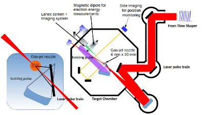
In the Resonant Multi-Pulse ionization injection scheme (see Fig. 1) only one short-wavelength laser system (e.g a Ti:Sa) is needed. The long wavelength driving pulse of the two-color scheme is replaced by a short wavelength, resonant multi-pulse laser driver. Such a driver can be obtained via temporal shaping techniques from the single, linearly polarized, standard CPA laser pulse, while the minor fraction of the Ti:Sa CPA pulse is frequency doubled and used as an ionizing pulse.
Due to the resonant enhancement of the ponderomotive force, a properly tuned train of pulses is capable of driving amplitude waves larger than a single pulse with the same energy [4, 5]. Noticeably, since the peak intensity of the driver is reduced by a factor equal to the number of train pulses, it is also possible to match the conditions of both particle trapping and unsaturated ionization (i.e. with low ionization percentage) of the active atoms level. Recently [6] new experimental results on the generation of such a time shaped pulses demonstrate that a multi pulse scheme is obtainable with present day technology and that plasma waves can be excited with this scheme [7]. Using Argon ( with ionization potential ) as a dopant gives us the possibility to obtain bunches with tens of of normalized emittance. Multi-pulse ionization injection with Argon requires trains with more than four pulses since ionization level is saturated with amplitude above at (see Fig. 3 in [3]).
3 1.3 GeV beam simulation
We report on a long acceleration length (of about 4 cm) simulation performed in a 2D cylindrical geometry with QFluid [8](see also the Appendix in [3]). The Ti:Sa laser system generates pulses that will pass through a beam splitter. The major portion of each pulse is time shaped as a train of resonant eight sub-pulses having FWHM duration of each, with peak power of 200/8 TW. The driving train is subsequently focused down to a spot of waist onto a capillary filled with Argon, obtaining a sequence of pulses with peak intensity and normalized amplitude of and , respectively. The frequency doubled pulse from the minor portion of the Ti:Sa pulse delivers and is focused with a minimum waist of . On-axis plasma background density is set to and is obtained by assuming full ionization of Argon up to level eight (ionization potentials of are below for so Argon ionization up to is achieved within the first cycles of the pulse).
To obtain a so long acceleration length pulse guiding technique is necessary since low-density plasmas don’t allow for pulse self-guiding at those pulse powers. The driver pulses are focused close to the entrance of the capillary (or gas-cell) and enter into the guide with a matched radius and radial density profile
| (1) |
The factor accounts for weakly nonlinear corrections and in the case of short pulses ( can be evaluated as [10]
which is very close to unity in our simulations.
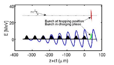
Simulation has been performed onto a moving cylinder of radius , length and a resolution in both radial and longitudinal directions of . Due to the tight focusing of the ionization pulse that diffracts in a scale , the bunch population growths and saturates (bunch charging phase) in about (see Fig. 2, green dots representing the longitudinal phase-space of the bunch in the charging phase) and the extracted bunch is trapped after of propagation of the ionizing pulse (see red dots in Fig. 2) in a phase of the bucket intermediate between the weak-trapping and the strong-trapping conditions (see Eqq. 2 and 3 in Ref. [3]).
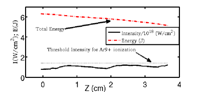
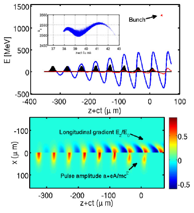
The driver pulses evolution through the of plasma shows a twofold behavior. Though peak intensity is remarkably stable (see the black line in Fig. 3), and no visible self-steepening occurs (we are well below the threshold for the onset of self-steepening since and according to [9] the growth of self-steepening occurs if ) sub-pulses of the rear part of the train propagate in the wake generated by all the preceding pulses, thus being partially exposed to the defocusing effect of the wake. As a final effect, a radial breathing of the rear pulses occurs with possible off-axis maxima of the local intensity, as it is apparent in Fig. 4 (bottom).
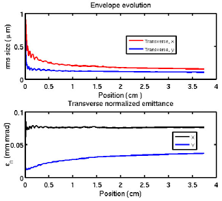
The final electron bunch of charge has energy 1.3 GeV, energy spread 0.49% rms and normalized emittance of and in x (laser polarization) and y directions, respectively. After 3.7 cm of propagation the electron bunch is still far from dephasing (see Fig. 4 top) and almost 70% of laser energy is still available for further energy boost. However, while normalized emittance looks stable in the last (see Fig. 5) due to the matched-beam configuration, the relative energy spread finds its minimum at and rapidly increases with further acceleration up to percent level. For high-quality oriented application, therefore, such a earlier truncation of particle acceleration limits the overall energy conversion efficiency of the scheme (at the present working point). We finally stress the remarkably low value of for the slice energy spread (with slice thickness of ).
The simulation ends when the pulses and the bunch are close to the plasma exit. Due to the use of the quasistatic approximation, QFluid cannot face with rapidly varying longitudinal plasma densities so we will be forced to use a different code to face with the plasma exit stage.
The ReMPI scheme uses a single laser system (a Ti:Sa in the present paper) so the driving train and the ionization pulse have no relative timing jitter. This opens the possibility of fine tuning the ionization-to-driver delay according to the requested bunch energy or length. The fine-tuning of the bunch duration is easily obtainable just by selecting the appropriate ionization-to-driver delay . Numerical simulations (supported by theory in 1D) show that the minimum bunch length is obtained when the ionization pulse is placed at the position of maximum potential (zero longitudinal electric field) and the trapped bunch is placed at the position of maximum accelerating gradient (i.e. exactly at the strong-trapping point). Starting from that configuration and further delaying the ionization pulse, the final bunch length increases. The fulfillment of the weak-trapping condition for the whole set of bunch electrons makes an upper limit of the bunch duration. Both the minimum and maximum obtainable values depend on the working point. In the current setup bunch lengths that can be obtained by simply delaying the ionization pulse are in the range . Optimization of the bunch length/energy tuning strategy is ongoing [11].
4 Estimates of FEL performance
In this section we will report on analytical results obtained with the bunch, having supposed an emittance preserving beamline to transport the bunch from the accelerator stage to the undulator. We stress, therefore, that the following results do not constitute the final stage of a start-to-end simulation but just the expected outcomes of FEL radiation in the case of a quality-preserving optics.
For an electron beam of energy , the resonance condition for the wavelength of the emitted radiation, in a planar undulator, is
| (2) |
where is the period of longitudinal variation of the on-axis magnetic filed for a planar undulator and K is the undulator parameter defined as:
| (3) |
being the peak value of the on-axis magnetic field and and respectively the electron charge, the electron mass and the speed of light.
| Bunch parameters | |
|---|---|
| beam energy [GeV] | |
| long. beam size (rms) [m] | |
| current intensity [A] | |
| norm. emittance [mmmrad] | |
| slice energy spread (%) | |
| Common FEL parameters | |
| undulator magnetic field [T] | |
| undulator period [cm] | |
| deflection parameter | |
| Output FEL parameters | |
| FEL wavelength [nm] | 2.0 |
| Twiss [m] | 6.16 |
| Pierce parameter | 0.0018 |
| inh. broad. gain length [m] | 0.702 |
| saturation power [MW] | 861 |
| saturation length [m] | 17.7 |
| coherence length [m] | 0.05 |
| sat. power with slippage [MW] | 826 |
The efficiency of energy transfer from electrons to the electric field and so the gain of the process are summarized by the FEL Pierce parameter ,
| (4) |
where is the planar undulator Bessel correction factor, of argument
and kA the Alfven current. The current is expressed in terms of the bunch root mean squared (rms) time duration and of the bunch charge as
| (5) |
The current density given by
| (6) |
where is the rms transverse size of the electron beam.
The gain length, determining the FEL growth rate, can be expressed in terms of as follows
| (7) |
The Pierce parameter gives an estimate of the natural bandwidth of the FEL, and rules also the power at saturation that writes
| (8) |
being the electron beam power, linked to the peak current and energy by the relation . Then, the length of the undulator section needed to reach the saturated laser power – the saturation length – is
| (9) |
where is the input seed power.
The effect of inhomogeneous broadening due to significant energy spread and emittance can be embedded in the previous formulae [12, 13]: both contribute to increase the gain and saturation length. Furthermore, since the longitudinal beam size becomes comparable to the coherence length, slippage corrections are taken into account resulting in an effective saturation power. Table 1 shows the results obtained using simple and analytical scaling laws [12, 13] to describe the FEL signal pulse evolution in terms of saturation length and saturation power accounting for the beam emittance, the energy spread and the slippage corrections for the reported beam.
5 Conclusions
We employed the new ReMPII scheme to (numerically) generate a 1.3 GeV electron bunch with outstanding quality (, and compactness by using a single Ti:Sa laser system and a preformed plasma channel of length 3.7 cm. To operate with the ReMPI scheme a small portion of the Ti:Sa pulse has been frequency doubled and tightly focused on the target to further ionize the dopant and extract electron from the background. The main portion passed through a time shaping device and after focusing by a large F/# paraboloid constituted the driving pulse(s) of the plasma wave. The scheme takes advantage of the virtual absence of jitter between the ionizing and driving pulses due to the usage of a single laser system. This opens the possibility to precisely determine bot the bunch length and energy of the final bunch. In the current setup numerical simulations show that bunches with duration from up to can be generated.
Analytical results of FEL performance, based onto a long bunch, show that powerful radiation of peak power exceeding can be generated with state-of-the-art undulator parameters, provided that quality-preserving beam optics from plasma exit to the undulator is employed.
6 Acknowledgments
We thank Giuseppe Dattoli for his help and suggestions in estimating the FEL performance with the electron beams discussed in the text. The research leading to these results has received funding from the European Union’s Horizon 2020 research and innovation program under Grant Agreement No 653782 - EuPRAXIA. We also acknowledge financial support from the ELI-ITALY Network funded by CNR.
References
- [1] L.-L. Yu, E. Esarey, C. B. Schroeder, J.-L. Vay, C. Benedetti, C. G. R. Geddes, M. Chen, and W. P. Leemans, Two-Color Laser-Ionization Injection, Phys. Rev. Lett. 112, 125001 (2014).
- [2] L.-L. Yu, E. Esarey , C. B. Schroeder, J.-L. Vay, C. Benedetti, C. G. R. Geddes, M. Chen and W. P. Leemans, Ultra-low emittance electron beams from two-color laser-ionization injection, Advanced Accelerator Concepts 2014 AIP Conf. Proc. 1777, 040019-1–040019-5; doi: 10.1063/1.4965621.
- [3] P. Tomassini, S. De Nicola, L. Labate, P. Londrillo, R. Fedele, D. Terzani and L. A. Gizzi, The Resonant Multi-Pulse Ionization Injection, Physics of Plasmas 24 (10), DOI: 10.1063/1.5000696 (2017)
- [4] D. Umstadter, E. Esarey, and J. Kim, Nonlinear Plasma Waves Resonantly Driven by Optimized Laser Pulse Trains, Phys. Rev. Lett. 72, 1224 (1994).
- [5] S. M. Hooker, R. Bartolini, S. P. D. Mangles, A. Tunnermann, L. Corner, J. Limpert, A. Seryi and R. Walczak, Multi-pulse laser wakefield acceleration: a new route to efficient, high-repetition-rate plasma accelerators and high flux radiation sources, J. Phys. B 47, 234003 (2014).
- [6] R.J. Shalloo, L. Corner, C. Arran, J. Cowley, G. Cheung, C. Thornton, R. Walczak, S.M. Hooker, Generation of laser pulse trains for tests of multi-pulse laser wakefield acceleration, NIM A 829, 1, 383–385 (2016).
- [7] J. Cowley, C. Thornton, C. Arran, R. J. Shalloo, L. Corner, G. Cheung, C. D. Gregory, S. P. D. Mangles, N. H. Matlis, D. R. Symes, R. Walczak, and S. M. Hooker, Excitation and Control of Plasma Wakefields by Multiple Laser Pulse, Phys. Rev. Lett. 119, 044802 (2017).
- [8] P. Tomassini and A.R. Rossi, Matching strategies for a plasma booster, Plasma Phys. Control. Fusion 58 034001 (2016).
- [9] J. Vieira, F. Fiuza, L.O. Silva, M.Tzoufras and W.B. Mori, Onset of self-steepening of intense laser pulses in plasmas, New. Journal of Physics 12, 045025 (2010).
- [10] W. Lu, M. Tzoufras, C. Joshi, F.S. Tsung, W.B. Mori, J. Vieira, R.A. Fonseca, L. O. Silva, Phys. Rev. ST Accel. Beams 10, 061301 (2007).
- [11] P. Tomassini et al., in preparation.
- [12] G. Dattoli, P. L. Ottaviani, and S. Pagnutti, Booklet for FEL Design, available at http://fel.enea.it/booklet/pdf/Booklet_for_FEL_design.pdf.
- [13] G. Dattoli, A. Renieri, and A. Torre, “Lectures on Free Electron Laser Theory and Related Topics" (World Scientific, Singapore, 1993).