TARANET: Traffic-Analysis Resistant Anonymity
at the NETwork layer
Abstract
Modern low-latency anonymity systems, no matter whether constructed as an overlay or implemented at the network layer, offer limited security guarantees against traffic analysis. On the other hand, high-latency anonymity systems offer strong security guarantees at the cost of computational overhead and long delays, which are excessive for interactive applications. We propose TARANET, an anonymity system that implements protection against traffic analysis at the network layer, and limits the incurred latency and overhead. In TARANET’s setup phase, traffic analysis is thwarted by mixing. In the data transmission phase, end hosts and ASes coordinate to shape traffic into constant-rate transmission using packet splitting. Our prototype implementation shows that TARANET can forward anonymous traffic at over 50 Gbps using commodity hardware.
1 Introduction
Users are increasingly aware of their lack of privacy and are turning to anonymity systems to protect their communications. Tor [28] is currently the most popular anonymity system, with over 2 million daily users [12]. Unfortunately, Tor offers neither satisfactory performance nor strong anonymity. With respect to performance, Tor is implemented as an overlay network and uses a per-hop reliable transport, increasing both propagation and queuing latency [29]. With respect to anonymity guarantees, Tor is vulnerable to traffic analysis [50, 52, 49, 62].
Users also have the option of anonymity systems with stronger guarantees such as DC-nets [20, 33, 67], Mix networks [21, 14], and peer-to-peer protocols [58, 31]. However, these systems either scale poorly or incur prohibitive latency and reliability, making them unsuitable for many practical applications.
In an effort to improve the performance of anonymity networks, research has built on the idea of network-layer anonymity (e.g., LAP [39], Dovetail [57], and HORNET [22]). Network-layer anonymity systems assume that the network infrastructure (e.g., routers) participates in establishing anonymous communication channels and assists in forwarding anonymous traffic. Intermediate anonymity supporting network nodes (or nodes for short) first cooperate with senders to establish anonymous sessions or circuits, and then process and forward traffic from those senders to receivers. While these systems achieve high throughput and low latency, the security guarantees of these systems are no stronger than Tor’s. Moreover, LAP and Dovetail leak the position of intermediate nodes on the path and the total path length, which reduces the anonymity set size, facilitating de-anonymization [22].
The problem space appears to have an unavoidable tradeoff: strong anonymity appears achievable only through drastically higher overhead [27]. In this paper, we aim to push the boundaries of this anonymity/performance tradeoff by combining the speed of network-layer anonymity systems with strong defenses.
To improve the anonymity guarantees, traffic analysis attacks need to be prevented, or made significantly harder/costlier to perform. The common method to achieve this is to insert chaff, which are dummy packets which to an adversary look indistinguishable from encrypted data packets. By mixing chaff with data packets, one can add noise to the underlying traffic patterns to defeat traffic analysis. For example, one can insert chaff to maintain a constant transmission rate on an adversarial network link, so that the traffic patterns observed by the observing adversary stay unchanged and leak no identifying information.
However, both existing methods of applying chaff traffic, i.e., constant-transmission-rate link padding [65, 31, 42, 41] and probabilistic end-to-end padding [44, 54], are unsatisfactory. On one hand, constant-transmission-rate link padding uses chaff to shape traffic between adjacent pairs of nodes making it perfectly homogeneous, thus provably concealing the underlying traffic patterns from a network adversary. However, a compromised node is able to distinguish chaff traffic from real traffic, giving link padding no anonymity guarantees when compromised nodes are present. On the other hand, probabilistic end-to-end padding enables end hosts to generate chaff traffic that is indistinguishable from real traffic, but existing schemes [44, 54] fail to fully conceal the end-to-end transmission rate and can be defeated by packet-density attack [59].
We take the best of both worlds and propose a new method of applying chaff traffic that has so far not been explored: an end-to-end padding scheme that shapes a flow’s traffic pattern into constant-rate transmission on all traversed links. At a flow’s origin, the sender divides its traffic into small flowlets that transmit packets at a globally-fixed constant rate. Each forwarding node modulates the outgoing transmission rate of each flowlet so that the transmission rate remains constant over time and also remains constant across all links traversed by the flowlet. This approach prevents traffic patterns from propagating across nodes. We call this technique end-to-end traffic shaping.
However, end-to-end traffic shaping is surprisingly tricky to achieve in the presence of natural packet loss, adversarial packet drops, or packet propagation delays. The main challenge for coordinated traffic shaping is how to maintain constant-rate transmission across all traversing links when a forwarding node’s incoming transmission rate is lower than the outgoing transmission rate. A simple approach that enables a forwarding nodes to create valid packets to send toward the destination appears promising, but unfortunately, this approach could be abused, as packet injection requires the cryptographic keys that the sender shares with downstream nodes. Moreover, such an approach would enable two malicious nodes that are on the same flowlet path to trivially link observed packets of the same flowlet. Similarly, allowing a node to replay existing packets cannot be permitted, as replicated packets themselves would constitute a trivially detectable pattern.
An initial idea is to enable each node to have a spare packet queue, containing packets that can be sent to make up for the difference between the incoming transmission rate and the required outgoing transmission rate. But this poses a conundrum: how can we fill up the spare packet buffer if the flowlet rate remains constant in the first place? Our solution is packet splitting, a cryptographic mechanism which allows an end host to generate a packet that splits into two different valid packets of the same size as the original packet at a specific node. Through splittable packets, an end host can fill up the spare packet queue at forwarding nodes, which in turn enables constant-rate transmission even in case of lost or delayed incoming packets.
In this paper, we propose TARANET, a scalable, high-speed, and traffic-analysis-resistant anonymous communication protocol, which uses the end-to-end traffic shaping assisted by packet splitting as one of its novel mechanisms. TARANET is directly built into the network infrastructure to achieve short paths and high throughput. It uses mixing for its setup phase and end-to-end traffic shaping for its data transmission phase to resist traffic analysis. Our paper makes the following contributions:
-
1.
We propose an efficient end-to-end traffic shaping technique that maintains per-flow constant-rate transmission on all links and defeats traffic analysis attacks. We also propose in-network packet splitting as the enabling mechanism for the end-to-end traffic shaping technique.
-
2.
We present an onion routing protocol that enables payload integrity protection, replay detection, and splittable packets, which are essential building blocks for end-to-end traffic shaping.
-
3.
We design, implement, and evaluate the security and performance of TARANET. Our prototype running on commodity hardware can forward over 50 Gbps of anonymous traffic, showing the feasibility to deploy TARANET on high-speed links.
2 Background and Related Work
This section presents background on network-layer anonymity protocols. We also discuss adversarial traffic analysis techniques to de-anonymize end points, focusing on those that current network-layer anonymity protocols fail to deter.
2.1 Network-layer Anonymity Protocols
Recent research [39, 57, 22] proposes network-layer anonymity systems that incorporate anonymous communication as a service of network infrastructures in the Internet and next generation network architectures [69, 32, 70]. The basic assumption of a network-layer anonymity system is that Autonomous Systems (AS) can conduct efficient cryptographic operations when forwarding packets to conceal forwarding information. Additionally, a network-layer anonymity system uses direct forwarding paths rather than reroute packets through overlay networks as in Tor [28]. This processing would be done on (software) routers, for instance, but more abstractedly the term node is used to refer to the device or set of devices dedicated to the anonymity system within an AS.
A network-layer anonymity system anonymizes its traffic by relying on ASes to collaboratively hide the forwarding paths between senders and receivers. We remark that a network-layer anonymity system can offer neither sender anonymity nor recipient anonymity as defined by Pfizmann and Köhntopp [53]. A compromised first-hop AS on the path can observe the sender of a message, violating sender anonymity. Similarly, a compromised last-hop AS can identify the receiver, which breaks recipient anonymity. Instead, a network-layer anonymity system offers relationship anonymity [53] that prevents linking two end hosts of a message.
Besides anonymity, the basic design goals for a network-layer anonymity system are scalability and performance. With respect to scalability, a network-layer anonymity system minimizes the amount of state kept on network routers who possess limited high-speed memory. With respect to performance, a network-layer anonymity system should offer low latency and high throughput.
HORNET [22] improves on the security guarantees for network-layer protocols by using full onion encryption to guarantee bitwise unlinkability. HORNET introduces several useful primitives for stateless onion routing, which we extend in TARANET.
HORNET is circuit-based like overlay systems, but it operates at the network layer. As with LAP and Dovetail, processing data packets at intermediate nodes requires only symmetric cryptography. This design comes at the expense of a relatively slow round-trip time for setup packets which requires nodes on the path to perform public-key cryptography at the start of each session. During setup, the sender establishes keys between itself and every node on the path. The sender embeds these keys along with routing information for each hop into the header of each subsequent data packet. Since the state is carried within packets, intermediate nodes do not have to keep per-flow state, which enables high scalability.
Through bit-pattern unlinkability in its traffic and confidentiality of the packet’s path information, HORNET can defend against passive adversaries matching packets based on packet contents. Nevertheless, the protocol is vulnerable to more sophisticated active attacks. HORNET headers are re-used for all data packets in a session, and payloads are not integrity-protected. Thus, HORNET cannot protect against packet replays since an adversary could change a payload arbitrarily, making the packet look indistinguishable from a legitimate new packet to the processing node. Such a replay attack can be used in conjunction with traffic analysis to insert recognizable fingerprints into flows, which can help de-anonymize communicating endpoints.
Lightweight anonymity systems
The first class of network-layer anonymity protocols proposed is the so-called lightweight system, which consists of two proposals, LAP [39] and Dovetail [57]. These systems defend against topological attacks by encrypting forwarding information in packet headers. However, in both schemes, packets stay unchanged from hop to hop, thus enabling bit-pattern correlation of packets at distinct compromised nodes.
2.2 Traffic Analysis Attacks
Traffic analysis aims to identify communicating endpoints based on metadata such as volume, traffic patterns, and timing. The literature broadly classifies traffic analysis techniques into passive and active, depending on whether the adversary manipulates traffic.
2.2.1 Passive Attacks
Flow dynamics matching
An adversary eavesdropping on traffic at two observation points (including an adversary observing the ingress and egress traffic of a single node) can try to detect whether (some of) the packets seen at the observation points belong to the same flow by searching for similarities among the dynamics of all observed flows [72, 45, 50, 47]. For example, the adversary can monitor packet inter-arrival times, flow volume [16], or on/off flow patterns [66, 71].
Template attacks
An adversary can construct a database of traffic patterns (templates) obtained by accessing known websites or other web-services through the anonymous communication system. When eavesdropping on the traffic of a client, the adversary compares the observed flows with the patterns stored in the database, and if a match is found the adversary is able to guess the website or web-service accessed by the client with high probability [34, 40, 64].
Network statistics correlation
Another possible attack consists in monitoring network characteristics of different parts of the network, and comparing them to the characteristics of targeted anonymized flows. For instance, by comparing the round-trip time (RTT) of a target bidirectional flow with the RTTs measured to a large set of network locations, an adversary can identify the probable network location of an end host in case the RTT of the flow showed strong correlation with the RTT to one of the monitored network locations [35]. Similarly, by simply the throughput (over time) of a unidirectional flow and comparing it with the throughput to various network location, the adversary can guess the end host’s location [48].
2.2.2 Active Attacks
Active traffic analysis uses similar techniques as passive traffic analysis, but it additionally involves traffic manipulation by the adversary, in particular packet delaying and dropping, to introduce specific patterns. Chakravarty et al. [18] show that active analysis can have high success rates even when working with aggregate Netflow data instead of raw packet traces.
Flow dynamics modification
By modifying the flow dynamics (inter-packet timings), the adversary can add a watermark (or tag) to the flow, which the adversary is then able to detect when observing the flow at another point in the network [66, 38, 36]. This attack is known as flow watermarking. A similiar attack, called flow fingerprinting, enables an adversary to encode more information into the flow dynamics, which can later be extracted from the same flow seen at another point in the network [37]. For both attacks, depending on the coding technique, flows may require more or fewer packets for the watermark/fingerprint to be reliably identified within the network.
Clogging Attacks
Flow dynamics modification requires that the adversary control multiple observation points in the network. Clogging attacks are similar, but the adversary only needs to be able to observe the target flow at a single network location. For these attacks, the adversary causes network congestion [50, 30], or fluctuation [19] at other nodes in the network, and then observes whether these actions affect the observed target flow. If so, it is likely that the target flow traverses the nodes at which congestion/fluctuation has been caused.
2.3 Chaff-based Defenses
Adding chaff traffic (also referred to as padding traffic or dummy traffic) is a defense mechanism that thwarts traffic analysis by concealing real traffic patterns. An important family of chaff-based anonymity protocols uses link padding [59, 65, 31, 42, 41]. Link padding, used together with link encryption, allows neighboring forwarding nodes to add chaff to shape the patterns of all traffic on a network link into either constant-rate transmission [59, 65] or a predetermined packet schedule [31, 42, 41]. However, because in link padding a node is able to distinguish chaff packets from real packets, attackers that compromise nodes are still capable of identifying the underlying traffic patterns and conduct traffic analysis.
Another class of chaff-based protocols uses end-to-end padding [44]. In the end-to-end padding scheme, end hosts craft chaff packets that traverse the network together with real packets, and the added chaff packets carry flags to inform the forwarding nodes about when to drop the chaff packets. Thus, an end host’s traffic demonstrates different patterns as the traffic traverse the network. Compared to link padding, in end-to-end padding a compromised node cannot distinguish chaff traffic from real traffic, and is thus unable to discover the real traffic patterns. Nevertheless, the existing work, defensive dropping [44], fails to fully conceal the timing information of the real traffic, and is trivially defeated by measuring packet density [59].
3 Problem Definition
We consider a scenario where an adversary secretly conducts a network mass-surveillance program. By stealthily tapping into inter-continental fiber links, or by controlling a set of domestic ISPs/IXPs, the adversary gains bulk access to network traffic. Besides matching identifiers to filter packets, the adversary is also capable of conducting traffic manipulation and traffic pattern matching. A pair of anonymity-conscious users would like to communicate through the network, hiding the fact that they are communicating from the adversary. The communication between the pair of users is bi-directional. Without loss of generality, we call the user that initiates the anonymous communication sender, and the other user receiver.
3.1 Network Assumptions
The underlying network is divided into ASes, or simply nodes. Each node forwards packets according to a routing segment. Each routing segment contains forwarding information for a node between the sender and the receiver. For a sender to reach a receiver, the sender can obtain a sequence of routing segments, named path.
Except the ingress and egress links that are needed as forwarding information through an AS, routing segments should leak no extra information about the end hosts or the path before or after the forwarding node. This property is satisfied by several next-generation Internet architectures that use source-controlled routing (e.g., SCION [70], NIRA [69], or Pathlet [32]), or in the Internet through IPv6 Segment Routing [9].
3.2 Threat Model
We consider a global active adversary, that is capable of controlling all links between any pair of ASes, or between an AS and an end host. This means that the adversary has bulk access to contents and timing information of packets on all links and can also inject, drop, delay, replay, and modify packets. We additionally assume that the adversary is able to compromise a fraction of ASes. By compromising an AS, the adversary learns all keys and settings, has access to all traffic that traverses the compromised AS, and is able to control the AS including delaying, redirecting, and dropping traffic, as well as fabricating, replaying, and modifying packets. We only guarantee relationship anonymity for end hosts if there exists at least one uncompromised AS on the path between sender and receiver. We remark that the adversary under this assumption is able to perform all traffic analysis attacks in Section 2.2.
3.3 TARANET Goals
Anonymity
TARANET aims to provide relationship anonymity (defined by Pfizmann and Köhntopp [53]) when a sender and a receiver share mutual trust. We refer to the relationship anonymity under this condition as third-party relationship anonymity. While requiring trust in receivers limits our protocol’s application scope, third-party anonymity is actually sufficient when communicating parties are authenticated end-to-end (e.g., VoIP), when avoiding censorship where the receiver (e.g., a foreign news site) is known not to cooperate with the censoring entity, when a warrant canary (e.g., www.rsync.net/resources/notices/canary.txt) has been recently updated for that endpoint, or when the receiver is a trusted node acting as a proxy.
High throughput and low latency
The processing overhead should be small, i.e., it should only require symmetric cryptographic operations and access to a small amount of easy-to-manage per-flow state. Consequently, an efficient implementation (running at line speed) on a network device should be possible with a small amount of extra hardware.
Scalability
Nodes should be capable of handling the large volume of simultaneous connections as observed on Internet core routers. TARANET aims to minimize the amount of per-flow state maintained. Specifically, TARANET guarantees that the amount of state on a router is bounded given a fixed throughput. Moreover, adding new nodes to the network should additionally not require coordination with all other nodes.
4 Protocol Design
Communication Model
Hosts communicate anonymously through TARANET-enabled Autonomous Systems (ASes) using flowlets. A TARANET flowlet allows an end host to send traffic anonymously at a constant rate for a fixed time period . All anonymous traffic is divided into a set of flowlets by end hosts to leverage TARANET’s service. Figure 1 graphs the lifecycle of a TARANET flowlet.
A flowlet’s life-cycle begins with a setup phase followed by a data transmission phase. At the beginning of the setup phase, a sender first anonymously retrieves two paths: a forward path from the sender to the receiver and a backward path from the receiver back to the sender. A path contains the routing segments, the public keys, and the certificates of all nodes between the two end hosts. One mechanism for anonymously retrieving paths is to have end hosts query global topology servers through TARANET flowlets that are established using network configuration information (e.g., distributed to end hosts through a DHCP-like infrastructure [22]). Another mechanism is to disseminate paths and public keys throughout the network to end hosts, as done in certain future network architectures (e.g., NIRA [69], Pathlets [32]). A third mechanism could be based on private information retrieval (PIR) [23], which allows to trade off a lower communication overhead for an increased computation overhead on the servers providing the network information and the keys.
Once the sender successfully obtains both paths, the sender and the receiver exchange two setup messages traversing the obtained paths. By processing a setup message, each on-path node establishes a shared symmetric key with the sender. The per-node shared key is later used to conceal routing information by layered encryption/decryption in the data transmission phase. To prevent storing per-flow cryptographic state on each node, a node encrypts the shared key using a local secret key that the node never reveals. The resulting encrypted shared key, which we call the Forwarding Segment (FS), is carried by all data packets and allows the node to dynamically retrieve its shared symmetric key.
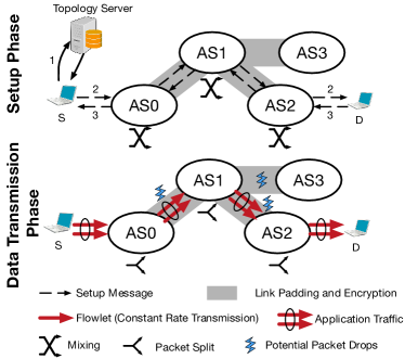
With routing segments, FSes, and per-node symmetric keys, the sender is able to create TARANET data packets that can reach the receiver. An on-path node can process a data packet with only symmetric cryptographic operations, enabling highly efficient packet forwarding. Within the first batch of packets along the forward path, the sender transmits all routing segments, FSes, and shared symmetric keys for the backward path, so that the receiver can send packets back to the sender.
Traffic analysis resistance
TARANET resists traffic analysis attacks by combining an onion routing protocol (an enhanced adaptation of the one in HORNET), a newly proposed end-to-end traffic shaping scheme, and mixing. First, compared to HORNET which provisions confidentiality, authenticity, and bit pattern unlinkability, TARANET additionally offers payload integrity protection, replay protection, and packet splitting, which is a vital enabling technique for the end-to-end traffic shaping scheme (Section 4.1). Second, for the data transmission phase, TARANET enables end-to-end traffic normalization for flowlet traffic. For each flowlet, the sender and receiver maintain a constant transmission rate shared by every end host. Each forwarding node maintains the same constant transmission rate for outgoing packets belonging to the flowlet (Section 4.2). Third, for messages in the setup phase, TARANET requires each node to conduct mixing [21] in order to prevent linking messages based on their timing and order (Section 4.3). Finally, to hide the difference between setup packets and data packets and to defeat a global eavesdropper that monitors the number of flowlets on links between nodes, TARANET additionally requires neighboring nodes to perform link encryption and link padding (Section 4.4).
The rationale for adopting different techniques for the setup phase and the data transmission phase is due to our observation of the different performance requirements in these two phases. Regarding the setup phase, assuming a large number of simultaneous connection setups, batching setup messages on a node will result in a small delay for the setup phase. Moreover, because changing the order of messages received by a node has no impact on the performance of the setup phase, we can randomize the order of messages within each batch. Finally, since processing a chaff setup message requires public-key cryptographic operations, creating chaff setup messages would result in a large computational overhead.
For the data transmission phase, on the other hand, because packet order is important for TCP performance, randomizing the message order severely impacts application performance. Additionally, because data packet processing is highly efficient, we can actively conduct traffic shaping on both end hosts and intermediate nodes by using chaff packets (Section 4.2).
4.1 TARANET Onion Routing Protocol
Like the HORNET onion routing protocol [22], the TARANET protocol offers bit-pattern unlinkability, payload confidentiality, and per-hop authenticity. Bit-pattern unlinkability eliminates any identifiers that facilitate packet matching. Payload confidentiality prevents leaking upper-layer sensitive information. Finally, each TARANET header contains per-hop MACs that protect the integrity of both the header and the payload, unlike HORNET, whose per-hop integrity guarantees only cover the header. Therefore, in TARANET, tampered or forged packets will be detected by benign nodes on the path and dropped immediately.
TARANET also adopts the scalable design of HORNET, i.e., using packet-carried forwarding state. Storing per-flowlet state at core routers requires a large amount of high-speed memory, precluding scalability. Thus, in line with state-of-the-art network-layer anonymity protocols [39, 57, 22], TARANET embeds all necessary forwarding state (e.g., onion decryption keys, next-hop information, control flags) in packet headers instead of storing the state on routers.
| Protocol | Bit-pattern unlinkability | Scalability | Payload Integrity | Replay Protection | Packet Splitting |
|---|---|---|---|---|---|
| HORNET | Yes | Yes | No | No | No |
| TARANET | Yes | Yes | Yes | Yes | Yes |
We highlight three new features that TARANET introduces for the data transmission phase compared to HORNET. First, integrity protection is extended to data packets’ payloads, eliminating tagging attacks targeting at manipulating data payloads to create recognizable patterns. Second, data packets within the same flowlet have unique identifiers bound to the packets themselves, enabling replay protection. Third, TARANET allows an end host to create special chaff packets, each of which splits into two packets at a specific node. To all other nodes, the original packet and the resulting packets are indistinguishable from ordinary data packets in the same flowlet. Split packets traverse the same path as other packets in the flowlet and their per-hop MACs need to be correct at each downstream node. Splitting a chaff packet into multiple packets plays a vital role in the end-to-end traffic shaping technique described in Section 4.2. We defer the detailed description of the technical aspects of packet splitting to Section 5.
Replay protection
In TARANET, each TARANET packet header is uniquely identifiable, enabling intermediate nodes to detect replay attacks by checking the header’s freshness. Specifically, an intermediate node can retrieve 3 fields from each packet: (1) a shared secret with the sender, (2) a per-packet Initial Vector (IV), and (3) a per-packet expiration time. The first two fields together uniquely identify a packet and are used as input to membership queries and for the insertions to the replay detector. The third field is used to check and drop expired packets.
TARANET nodes detect replayed packets by maintaining a rotating Bloom filters composed of 3 subject Bloom filters, as described by Lee et al. [43]. A packet received at is checked against all 3 filters and is only inserted into -th Bloom filter, where . The -th subject filter is cleared at time (N is an integer). The rotating Bloom filter guarantees that each packet inserted has a lifetime between and , where is the maximum lifetime of a packet. To reduce cache misses and increase performance, we also use blocked Bloom filters [56] instead of standard Bloom filters.
Replay detection state is not per-flow state, since the size of the detector grows linearly with its node’s bandwidth, and not with the number of flowlets traversing that node. The size of our detector is ~15 MB111Computed using the CAIDA dataset described in Section 7. for a 10 Gbps link when the false positive rate is at most and (the maximum packet lifetime we consider in Section 5.4.1). Each false positive result causes the corresponding packet to be dropped. Given that the packet drop rate of the Internet is around 0.2% [61], we could reduce the detector’s size by allowing higher false positive rate.
4.2 End-to-end Traffic Shaping
Flowlet
Our basic idea for defending data transmission against traffic analysis is to shape traffic from heterogeneous applications into constant-rate transmission. A flowlet is the basic unit through which an end host is able to transmit packets at a constant throughput and for a maximum lifetime . During the lifetime of a flowlet, the end host always transfers packets at rate , inserting chaff packets if necessary. More generally, if an end host needs to transfer data at rate for time , it initiates a sequence of flowlet batches, each of which contains simultaneous flowlets.
An end host shuts down a flowlet before the flowlet expires when there is no more data to send. When shutting down multiple simultaneous flowlets, an end host pads each flowlet with a random number of packets to prevent linking the flowlets by their expiration times. A node erases local state and terminates a flowlet when there are no more packets in its outgoing packet queue.
The key property of a flowlet is to maintain constant transmission rates not only at end hosts but also on all traversed links, for which the flowlet relies on end-to-end padding instead of link padding. In link padding, a pair of neighboring intermediate nodes coordinate to inject chaff to maintain a constant sending rate on a link. While link padding is effective against a network adversary, it is insufficient in the case of compromised nodes, since they can distinguish chaff inserted by neighbors from actual data packets. To defend against compromised nodes, we need chaff packets that are indistinguishable from data packets. Because TARANET uses onion encryption as a basic building block, one can create such indistinguishable chaff only when possessing shared keys with all traversing nodes. Thus, only sending end hosts are able to create such chaff.
Necessity of packet splitting
To achieve constant-rate transmission, every flowlet should ideally arrive and leave with rate at every node. However, drops/jitter may cause the incoming rate to vary: a higher rate is absorbed by the queues, but a lower rate requires that the node be able to produce “extra packets”, which need to resemble legitimate packets to any downstream node. This implies that these packets must also be generated by the sender like end-to-end chaff. But since the sender cannot send at a rate higher than , it cannot send additional packets for the nodes to cache and use when needed. The only option then seems to be to have very long queues, and let each node fill a significant fraction of them with packets when the transmission of the flowlet first begins, before the node starts forwarding packets for that flowlet. However, this requires far too much state, and also adds significant latency in terms of time to the first byte, making this option unfeasible. The apparent dilemma can be solved with a technique we call packet splitting.
The packet splitting technique allows an end host to create a packet that can be split into two packets at a specific intermediate node.222The general packet splitting technique supports a n-way split. We consider only two-way packet splits because of limited Maximum Transmission Units (MTU) in the network. The resulting packets should be indistinguishable from other non-splittable packets. This requirement indicates that the resulting packets should still traverse the same path and reach the recipient’s end host. We present the algorithm to split packets in Section 5.
Traffic shaping for flowlet outgoing rate
To enable end-to-end traffic shaping, for each on-path node , an end host selects a slot in its transmission buffer with probability and fills in a newly generated splittable chaff packet that will split at node . As an optimization, the end host can also select a slot that already contains chaff packets and replace it with splittable chaff packets. When a node receives a packet that should be split at the node, the node performs the split and caches resulting packets in its chaff packet queue.
Each node maintains a per-flowlet chaff queue of cached chaff packets. To guarantee an invariant outgoing flowlet rate, nodes periodically output a data packet from the data packet queue. In case that the data packet queue is empty, the node outputs a chaff packet from the flowlet’s chaff queue. We limit the chaff queue size by a maximal length . In the (unlikely) scenario where the chaff queue is also empty, a local per-flowlet failure counter is increased. When exceeds a threshold negotiated during flowlet setup, the node terminates the flowlet. is a security parameter of the flowlet that determines how sensitive the flowlet is against potential malicious packet drops.
When a node shuts down a flowlet, an intermediate node no longer receives packets from upstream nodes. It will first drain its local chaff packet queue and then terminate the flowlet when the threshold is reached. We remark that such a termination process results in successive termination on nodes and small variable intervals between termination times on different nodes because of the variable number of cached chaff packets.
We remark that both the chaff queues and failure counters constitute per-flow state. Nevertheless, the amount of state stored on a node is bounded by the node’s bandwidth. Because each flowlet consumes a fixed amount of bandwidth, a node with fixed total bandwidth is only capable of serving a fixed number of flowlets. Thus, the amount of state that a node maintains for its flowlets is bounded given its total available bandwidth. Accordingly, a node will have to refuse setup messages for new flowlets if its bandwidth is already fully occupied. We evaluate the amount of state the queues require in detail in Section 7.
4.3 Mixing in the Setup Phase
Each TARANET node applies a basic form of mixing when processing setup messages. After a setup message is processed by an intermediate node, the node queues the message locally into batches of size . Once there are enough setup messages to form a batch, the node first randomizes the message order within each batch and then sends out the batch.
Through batching and order randomization, a TARANET node aims to obscure the timing and order for setup messages. An adversary that observes both input and output setup messages of a non-compromised node cannot match an output packet to its corresponding input packet within the batch.
The batching technique introduces additional latency because the setup messages have to wait until enough messages are accumulated. Assume that is the number of incoming setup messages every second, the added latency can be computed as . Given the large number of simultaneous connections within the network, the introduced latency is very low, as shown by our evaluation in Section 7.2.
4.4 Link Encryption and Padding
Each pair of neighboring TARANET nodes agree upon a constant transmission rate upon link setup. The negotiated transmission rate determines the maximum total rate for data packets. When the actual transmission rate exceeds the negotiated rate on a link, the sending node drops the excessive packets. When the actual transmission rate is lower than the negotiated rate, the sending node will add chaff traffic. The chaff traffic inserted by an intermediate node to shape traffic on a link only traverses the link and is dropped by the neighboring node.
To prevent an adversary observing a link between two honest nodes from distinguishing chaff traffic from actual data traffic, all pairs of neighboring nodes negotiate a symmetric key through the Diffie-Hellman protocol, and use it to encrypt all packets transmitted on their shared link. This also makes setup messages and data packets indistinguishable.
As an optimization to reduce chaff traffic and improve bandwidth usage, we additionally allow neighboring nodes to agree on a schedule of transmission rates as long as transmission rate is detached from the dynamics of individual traffic rates. For example, because the actual link rate on a link often demonstrates similarity at the same time of different days, we can reduce the amount of chaff traffic by setting the transmission rate between to . is the historic average transmission rate between , is the standard deviation for the transmission rate, is a factor that allows administrators to account for temporal changes of the bandwidth usage.
5 Protocol Details
This section presents the details of TARANET data packet formats and processing functions. We show how to create a fixed-size packet that can be split into two new packets of the same size whose per-hop MAC can still be verified. Using the packet processing functions, we present the TARANET data transmission phase on end hosts and intermediate nodes.
5.1 Notation
We first describe our notation. In general, stands for the symbol of a specific direction , which is either forward (src to dst) or backward (dst to src). indicates the symbol belongs to -th node on the path in direction . For simplicity, we denote the set of all for a path as . We also define a series of string operations: is a string of zeros with length ; is the length of the string ; refers to the substring between -th bit to -th bit of string where starts from 0; stands for concatenation of string and . Table II summarizes the notation in this paper.
| Symbol | Meaning |
| security parameter used in the protocol | |
| size of per-hop segment | |
| size of control bits and expiration time | |
| maximum path length permitted by the protocol | |
| fixed-size of a data packet payload | |
| path of a specific direction | |
| length of a path | |
| the -th node on path | |
| , | the private and public key pair of node |
| a hash function to generate the key for | |
| routing segment, e.g., the ingress and egress ports | |
| expiration time for a packet at node | |
| forwarding segment | |
| a symmetric onion key shared with the sender | |
| per-packet initial vector | |
| per-hop | |
| the opaque component of a packet header | |
| onion data packet |
5.2 Initialization & Setup Phase
In the setup phase, the sender node aims to anonymously establish a set of shared keys with all nodes on the forward and backward path, and a shared key with the receiver. In the following protocol description and in our implementation, we use HORNET’s Sphinx-based single-round-trip setup [22]. Note that we can also set up flowlets using Tor’s telescopic method [28] which increases latency, but preserves perfect forward secrecy.
Once the setup phase is complete, in addition to the shared keys, the sender also obtains from each node on both paths a Forwarding Segment (FS) [22, Section 4]. The FS created by the node contains the key shared between the sender and that node and the routing information which tells the node how to reach the next hop on the path. The FS is encrypted using a secret value known only to the router that created the FS. As shown in Section 5.4, these FSes are included in every data packet: each node can then the retrieve the FS it created, decrypt it, and recover the packet processing information within. Unlike HORNET, we do not store the expiration time exp in a FS, but include it alongside the FS in the packet (see Section 5.3.2). This allows the sender to set a different expiration time for each packet and limit the time window in which the packet is valid, which is necessary for replay protection.
5.3 Data Packet Processing
5.3.1 Requirements
TARANET data packets are fixed-size onion packets whose integrity is protected by per-hop MAC. Processing these packets should satisfy the following three requirements:
-
•
An output packet cannot be linked to the corresponding input packet without compromising the processing node’s local secret value.
-
•
Processing a packet cannot leak a node’s position on the path.
-
•
Processing a packet cannot change the packet size regardless of underlying operations.
The last requirement is particularly challenging to satisfy, since TARANET allows flow mutations. Consider the split operation, which takes a fixed-size packet and creates two uncorrelated packets of the same size. The splitting procedure needs to ensure that subsequent nodes can verify the MACs in both new packets.
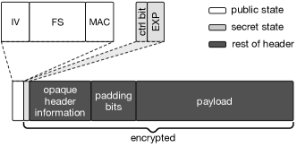
5.3.2 Data packet format
TARANET data packets are shown in Figure 2. At the beginning of each packet is an field that carries a fresh initial vector for each packet in a flowlet. After the field are four fields that form an onion layer: an FS, a per-hop MAC, control bits, and the expiration time. The rest of the fields, including the rest of header information, padding bits, and the payload, are encrypted, and are thus opaque to the processing node.
When a packet arrives, the first three fields are accessible to a node without requiring cryptographic processing, so we call these fields as public state. The control bits and the expiration time are only available after the node decrypts the packet, so they are called secret state. In addition, each header is padded to a fixed size regardless of the actual number of nodes on the path, and the padding bits are inserted between the header and the payload.
5.3.3 TARANET packet creation
Both end hosts generate data packets using a subroutine shown in Algorithm 1. The subroutine creates an onion packet to be forwarded from node to node . For each onion layer, it computes a per-hop MAC (Line 18) and onion-encrypts both the header (Line 16) and the payload (Line 18).
One important feature of this onion encryption algorithm is to add per-hop state (specifically, an FS, a MAC, control bits and an expiration time) to the packet header without changing its total size. The function achieves this feature by strategically pre-computing the padding bits in the header (Line 9) to ensure that the trailing bits of header after encryption are always equal to . As a result, the trailing zero bits can be truncated without losing information when the header is encrypted again (Line 16).
Normally, an end host creates a packet that traverses the whole path from the first node to the last node . It generates such a packet by setting , , and all in function create_onion_routine.
Generate splittable packets
Creating a data packet that can be split into two packet requires an end host to first create two children packets and then merge them into a single packet. Because we require all packets to have the same size, i.e., both children packets have to be of the same size as their parent, the key challenge is to guarantee that the per-hop MACs in the children packets successfully verify even after the splitting node adds padding bits to the children packets. For this reason, the splitting node generates padding bits by a PRG keyed by the key shared with the end host, so that the end host can predict the padding bits and pre-compute the per-hop MACs in both resulting packets accordingly.
Algorithm 2 shows the function to
create a splittable data packet. At a high level, create_splittable_data_packet invokes the
create_onion_routine three times: it first creates two
children packets using
create_onion_routine (Line 7 and
11), merges the resulting packets into a
new payload (Line 13), and finally executes
create_onion_routine again to generate the parent packet
(Line 17). To ensure the
correctness of the per-hop MACs in the children packets after the payloads are
padded, the function generates the padding bits using a PRG keyed by the shared key
between the end host and the splitting node so that the latter can re-generate the padding bits accordingly
(Lines 5 and
6). After the MACs are computed for the
children packets, the deterministic padding bits are truncated so that two
children packets can fit into the payload of their parent packet.
5.3.4 Onion layer removal
Nodes remove onion layers when processing data packets. It essentially reverses a single step of create_onion_routine. Algorithm 3 details this five step process. First, the intermediate node retrieves the symmetric onion key shared with the sender (Line 5); second, the node verifies a per-hop MAC using a key derived from (Line 6); third, the node ensures that the packet’s size remains unchanged by adding padding bits to the header and decrypting the resulting padded header with a stream cipher; fourth, the control bits are extracted (Line 8); finally, the payload is decrypted (Line 9) and the next initialization vector is obtained by applying a keyed with to the current (Line 10).
Note that the onion layer removal algorithm is different from a simple decryption in two ways. First, the size of the packet remains the same after processing, which prevents leaking information about the total number of hops between the sender and receiver. Second, the processing only happens at the head of the packet, which reveals no information about the processing node’s position on the path.
Depending on the value of control bits , the intermediate node performs one of the following two actions: FWD, or SPLIT. A node can split a data packet into two new packets by Algorithm 4. First, the payload is split into two new packets (Line 4). Then the node pads both newly generated packets to the fixed size using pseudo-random bits obtained from a PRG keyed by (Line 5 and 6).
5.4 Data Transmission Phase
5.4.1 End host processing
To send packets to receiver , sender first makes sure that the flowlet has not expired. Then chooses a value , which has to be larger than its local time plus the end-to-end forwarding delay plus the maximum global clock skew. We expect that adding 1 s to the local time would be adequate for most circumstances. However, cannot set the packet expiration time to be equal at every hop, as otherwise this value could be used as common identifier (which violates the bit-pattern unlinkability property. Instead, chooses an offset uniformly at random, for each node on the path. For every packet sent out, determines and computes for each node. The value needs to be chosen large enough to ensure that the interval overlaps with the intervals of a large number of other concurrent flows. We expect that s would be a safe choice.
After determining , also needs to decide which flow mutation actions the packet will adopt. In case of packet splitting, also needs to decide where to split the packet. For a packet that is forwarded to the receiver without being split, we denote the payload to send is . For a packet that is split, we denote the payloads of the children packets as and . Let be the index of the node where the packet is split. Accordingly, , . Third, uses to encrypt the payload. This end-to-end encryption prevents the last hop node from obtaining information about the data payload. also generates a unique nonce for the packet. If the packet is splittable, generates another two unique nonces and . Fourth, if the packet will be split, creates the packet by
| (1) |
If the packet will only be forwarded to the receiver without a splitting action, creates the packet by
| (2) |
Finally, forwards to the first hop node towards the receiver.
The process by which sends packets back to is similar to the above procedure, but will use the forwarding segments and onion keys for the backward path. However, right after finishes the setup phase, has not yet obtained , , nor . In the TARANET data transmission phase, the first packet that sends to includes , and as the payload.
When an end host ( or ) receives a data packet , it can retrieve the data payload from the packet by The resulting can thus be decrypted by to retrieve the plaintext payload.
5.4.2 Intermediate node processing
When a node receives a data packet , with the local secret , it first removes an onion layer by
| (3) |
Note that the MAC must check in remove_onion_layer for the process to move on. Otherwise, the node simply drops the packet. Then, the node checks and ensures that the flowlet has not expired. Afterwards, the node checks the control bits belonging to the current hop. If , the resulting payload must contain two sub packets. The node creates two children packets , :
| (4) |
Lastly, if the packet is not dropped, the node forwards the resulting packet according to the routing decision .
6 Security Analysis
We discuss TARANET’s defenses against passive (Section 6.1) and active attacks (Section 6.2). We also conduct a quantitative analysis of TARANET’s anonymity set size using the Internet topology and real-world packet traces (Section 6.3). Our result shows that TARANET’s anonymity set is 4 to 218 times larger than those of LAP and Dovetail. Finally, we present a formal proof that the TARANET protocol conforms to an ideal onion routing protocol defined by Camenisch and Lysyanskaya [17].
6.1 Defense against Passive Attacks
Flow dynamics matching
In flow-dynamics matching attacks [24, 51], adversarial nodes can collude to match two observed flows by their dynamics, such as transmission rate. TARANET prevents such attacks by normalizing the outgoing transmission rate of all flowlets through the use of chaff traffic. Adversarial nodes are unable to distinguish chaff traffic from real traffic. Accordingly, no flow dynamics are available to the adversary to perform matching.
Template attacks
TARANET enables end hosts to shape their traffic by adding chaff packets to hide their real traffic patterns. The resulting traffic pattern of an outgoing flowlet is uniform across the network. In addition, all TARANET packets have the same length, preventing information leakage from packet length. The combination of these two features completely neutralizes template attacks.
Network statistics correlation
These attacks rely on the capability of the adversary to observe macroscopic flow characteristics which leak de-anonymizing information. Because of the uniformity of flowlets, no such information is leaked in TARANET for isolated unidirectional flows. However, if the attacker is able to link the flowlets corresponding to a bidirectional flow by their starting or ending time, then an attack based on the RTT (see Section 2.2.1) could still be possible. Such an attack can be thwarted by adding delays for setup packets and flowlet start at the receiver, according to the path length (the shorter the path, the longer the delay), as suggested by previous work [22, Section 5.1].
6.2 Defense against Active Attacks
Tagging attacks
A compromised node can modify packets adding tags that are recognizable by downstream colluding nodes. This enables flow matching across flows observed at different nodes [55]. TARANET defends against such attacks through its per-hop packet authenticity (see Section 5). A benign node will detect and drop any modified packet.
Clogging attacks
In clogging attacks, an adversary intentionally causes network congestion [50, 30], or fluctuation [19] to create jamming or noticeable network jitter on relay nodes, and match such patterns to deanonymize the path. Different from throughput fingerprint attacks that aim to exert no influence on existing traffic patterns, clogging attacks aggressively change the traffic patterns on victim links and are prone to detection. First, clogging attacks in TARANET itself require DDoS capabilities because of nodes’ high bandwidth within the network. In addition, TARANET nodes attacked by clogging would run out of cached chaff packets, which in turn shuts down the flowlet and prevents any additional matching. Moreover, given the large number of flowlets in the network at any given time, the number of flowlets terminated due to normal operations is large, which hides the fact that the specific attacked flowlet is terminated.
Flow dynamics modification attacks
Traffic pattern modulation attacks require attackers to modulate inter-packet intervals to either create recognizable patterns (e.g., flow watermarking attacks [38, 36]), or embed identity information (e.g. flow fingerprinting attacks [37]), so that downstream adversarial nodes can deanonymize traffic by extracting the introduced traffic patterns. Depending on the amount of perturbation introduced by the adversary, we can distinguish two cases. In the first one, the adversarial actions fail to exhaust the cached chaff packets on the node under attack for the target flowlet. In this case, the outgoing rate for the flowlet at the node remains unchanged, and the attack is ineffective. In the second case, the victim node runs out of cached chaff packets for the target flowlet. In this case, the node terminates the flowlet to prevent downstream nodes from observing the injected patterns.
6.3 Anonymity Set Size Evaluation
Relationship anonymity set
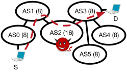
Network-layer anonymity protocols are vulnerable to passive attacks based on network topology information launched by a single compromised AS. Compared to overlay-based anonymity systems [28] that allows global re-routing, traffic of network-layer anonymity protocols follows paths created by underlying network architectures. By observing the incoming and outgoing links of a packet, a compromised AS can derive network location information of communicating end hosts. For example, in Figure 3(a), by forwarding a packet from AS1 to AS3, AS2 knows that the sender must reside within the set {AS0, AS1} and the receiver falls into the set {AS3, AS4, AS5}. We name the former anonymity set sender anonymity set, denoted as , and call the latter anonymity set recipient anonymity set, denoted as . Accordingly, we define relationship anonymity set .
To evaluate relationship anonymity of different protocols, we use anonymity-set size as the metric. By definition of , the anonymity-set size . In Figure 3(a), there are 8 hosts in both AS0 and AS1. Thus, . Similarly, we can calculate that and .
Protocol designs influence corresponding anonymity-set sizes. In LAP and Dovetail, by analyzing header formats, a passive adversary can determine its position on the packet’s path, i.e., its distances from the sender and the receiver [39, 57]. In Figure 3(a), if the adversary in AS2 knows the sender is 2 hops away and the receiver is 1 hops away through analyzing packet headers, it can deduce that the sender must be in AS0 and the receiver must be in AS3. The resulting anonymity-set size is reduced to 8 * 8 = 64. In comparison, TARANET and HORNET’s header designs prevent their headers from leaking position information.
Experiment setup
We use a trace-based simulation to evaluate anonymity set sizes of different network-layer anonymity protocols in real world scenarios. We obtain the real-world AS-level topology from CAIDA AS relationship dataset [1]. We also annotate each AS with its IPv4 address space using the Routeview dataset [8]. In addition, we estimate real-world paths using iPlane traceroute datasets [6]. We use the traceroute traces on Dec. 12th, 2014. For each IP address–based trace, we convert it to AS path. Our preliminary analysis shows that the median AS path length is 4 and the average AS path length is 4.2. More than 99.99% of AS paths have length less than 8.
For each AS on a path in our path dataset, we compute the sizes of the relationship anonymity sets observed by the compromised AS in one of two scenarios: 1) the AS knows its position on path as in LAP and Dovetail; 2) the AS has no information about its position on the path as in HORNET and TARANET. To compute anonymity set sizes, we first derive relationship anonymity sets composed by ASes. Then we compute the number of hosts in the ASes as the size of anonymity set size. We approximate the number of hosts within an AS by the number of IPv4 addresses of that AS.
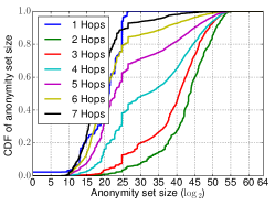
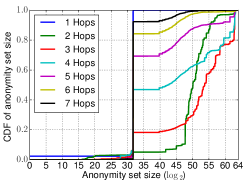
Result
Figure 3(b) demonstrates CDFs of anonymity-set sizes for LAP and Dovetail observed by a compromised AS. Figure 3(c) shows the CDF of anonymity-set sizes for TARANET and HORNET. In general, anonymity-set sizes of TARANET and HORNET exceed with probability larger than 95% regardless of the adversary’s on-path positions. The 90th percentiles of anonymity-set sizes of TARANET and HORNET are 4– times larger than those of LAP and Dovetail depending on the distances between senders and receivers. We remark that when an AS is 6 or 7 hops away from a sender, it is the last-hop AS with high probability, because 99.99% paths are less than 8 hops long. When the compromised ASes are 1 hop away from senders and when the ASes are close to receivers (6–7 hops away from senders), the gap between TARANET/HORNET and LAP/Dovetail is largest.
Topology-based attacks and traffic analysis
In LAP, Dovetail, and HORNET, when an adversary compromises more than 1 AS on a path, he/she can correlate observation from different non-adjacent ASes by traffic analysis, such as flow fingerprint attacks [37], to facilitate topology-based attacks. Assume that an adversary compromises ASes and observes a series of sender anonymity sets and a series of recipient anonymity sets . The resulting relationship anonymity set size . For example, in Figure 3(a), if the adversary compromises AS0 besides AS2 and correlates traffic from the same flowlet, the resulting relationship anonymity-set size is only () compared to when only AS2 is compromised.
TARANET improves over LAP, Dovetail, and HORNET by introducing defense against traffic analysis (see Section 6.1 and 6.2). By defeating traffic analysis and preventing correlation of flowlets at multiple non-adjacent ASes, TARANET enlarges the observed relationship anonymity set size. The resulting relationship anonymity set is only the smallest one among the relationship anonymity sets observed by non-collaborative compromised ASes. . For instance, when the adversary compromises AS0 besides AS2 and uses traffic analysis to correlate observed flowlets, the resulting relationship anonymity-set size increased to .
6.4 Formal Proof of Security
Proof of TARANET security comes into two parts: the security proof of TARANET’s setup phase protocol, and the security proof of TARANET’s data transmission phase. We derive the security of TARANET’s setup phase by the security of the Sphinx protocol [25], because TARANET’s setup phase protocol directly uses the Sphinx protocol and Danezis and Goldberg have demonstrated that the Sphinx protocol realizes an ideal onion routing protocol defined by Camenisch and Lysyanskaya [17].
In this section, we focus on the security of TARANET’s data transmission phase and prove that TARANET’s data transmission phase is equivalent to an ideal onion routing protocol based on UC framework [17]. According to Camenisch and Lysyanskaya, a protocol is an ideal onion routing protocol if it offers four properties: correctness, integrity, wrap-resistance, and security. We briefly rephrase the definitions of four properties as follows:
-
•
Correctness. The protocol should operate correctly without adversaries.
-
•
Integrity. There exists an upper bound for the protocol, such that an adversary cannot forget a message that traverse more than hops in the network.
-
•
Wrap-resistance. Given an output packet of an uncompromised node, an adversary cannot forget the corresponding input packet.
-
•
Security. An adversary cannot distinguish among packets that enter an uncontrolled node even if the adversary is able to 1) select paths for the packets forwarded by , 2) control all nodes on the path except , and 3) observe all input and output packets of except the challenge packets.
6.4.1 Correctness
A careful scrutiny of Section 5 should suffice to demonstrate the correctness of TARANET’s data transmission protocol.
6.4.2 Integrity
We show that with significantly less than work, an adversary cannot forge a message (, , , , ) that traverses more than hops nodes , , , in the network, even if the adversary learns all the secret keys , , , for the nodes on the path. We construct a proof of contradiction.
For convenience, we introduce a series of notations:
| (5) | ||||
| (6) | ||||
| (7) | ||||
| (8) |
Assume that the adversary can create a message (, , , , ) that traverses , , , . We can rewrite the message received by , (, , , , ), as follows:
| (9) | ||||
| (10) | ||||
| (11) |
where and .
In order for the MAC to check on node so that will forward the packet, we need:
| (12) |
If we substitute Equation 9, 10, and 11 into Equation 12, the right side of Equation 12 becomes a function with input (, , , , , , , ):
| (13) |
Before continuing, we first prove the following lemma:
Lemma 6.1.
With significantly less than work, an adversary can only distinguish (, , , , , , , ) from a random oracle with negligible probability.
Proof.
We prove a statement equivalent to the lemma: with significantly less than work, an adversary cannot find two sets
| (14) |
such that they lead to the same value of . We will prove this by proof of contradiction.
Assume the adversary found two distinguished values that yields the same value of . Because MAC is a random oracle, with significantly less than work, the attacker has to guarantee:
| (15) | ||||
| (16) |
Given the definition of and Equation 15, because is a pseudo-random permutation and is collision resistant, the adversary must have .
In addition, Equation 16 determines , . We will show that the latter means
| (17) |
Consider the last bits of and . By Equation 11, we have
| (18) |
Because is a secure pseudo-random generator, the following equation holds
| (19) |
Or
| (20) |
Since and are two independent random oracles and their inputs do not overlap, the attacker has to ensure , , , , and .
The equation that implies , , and , because is a random oracle. Repeating this logic, we will get Equation 17.
Finally, given and Equation 17, the attacker, with significantly less than work, has to make sure that . ∎
Let
| (21) |
We now can substitute Equation 10 and 21 into Equation 13 and rewrite the latter as:
| (22) |
Because MAC is not used in , the right hand side of the above equation is also a random oracle, which we can denote as
| (23) |
To sum up, in order for the MAC to check on node , the attacker needs to find the solution to
| (24) |
with two independent random oracles and . With significantly less than effort, the adversary can only succeed with negligible probability, which contradicts the assumption.
6.4.3 Wrap resistance
We prove that given a packet , an adversary cannot output a message with significantly less than work, so that processing of the former packet on an uncompromised node leads to the latter one.
If the adversary can succeed with significantly less than work, it is necessary that
| (25) |
Because , , , and are all random oracles and is unknown to the adversary, with significantly less than work, the adversary can only succeed to generate correct values of (, ) with negligible probability.
6.4.4 Security
To prove the security property, we construct the following game . Given an uncompromised node , the adversary selects two paths () and () where and . The nodes following are not necessarily the same sets of the nodes and the length of two paths can be different. The adversary is also able to choose all secrets for all nodes except for N, including the public/private keys and local secrets. Moreover, the adversary can also arbitrarily decide the contents of payload .
The challenger randomly selects a bit and proceeds in one of the two following ways:
. The challenger establishes a flowlet through the path and then creates a data packet with payload chosen by the adversary. The challenger outputs , which can be sent to node . We use to represent the corresponding packet received by node () on the path.
. The challenger establishes a flowlet through the alternate path and outputs a data packet (, , , , ) that can be sent to .
Given the output , the adversary is challenged to determine . The adversary can additionally input up to messages so long as they are not equal to .
The adversary’s advantage is defined as
We will show that the advantage is negligible with less than work.
Proof.
We use a hybrid-game method by establishing the following two new games and . The definition of is the same as except that we require that , i.e., the first node is uncompromised. We further define , whose assumption is the same as with only one exception that are randomly drawn from the corresponding domains.
First, because in , the message are all randomly drawn, the adversary’s advantage in guessing the bit is 0. Next, we would show that in a chain of game , the adversary can only distinguish a game from the previous game with negligible success probability with significantly less than work.
. On one hand, it is obvious that an adversary who can succeed in is able to succeed in as the former one is a more general game. On the other hand, because the adversary fully control nodes and can thus emulate their packet processing, the adversary can win game if s/he can win .
. In order to distinguish from , the following statements must be true:
-
•
The adversary can distinguish (; ) from randomness without knowing . Because is pseudo-random permutation with security parameter , the probability that the adversary succeeds with less than work is negligible.
-
•
The adversary can distinguish
(26) from random bits. Because is secure pseudo-random number generator, and the adversary has no knowledge of , the probability that the adversary succeeds is negligible.
-
•
We can repeat the same logic to show that it is impossible to distinguish and from random bits with non-negligible probability with significantly less than work.
∎
7 Evaluation
This section describes our implementation of TARANET, a performance evaluation,and our evaluation of bandwidth overhead added by end-to-end traffic shaping.
7.1 Implementation on High-speed Routers
We implement TARANET’s setup and data transmission logic on a software router. We use Intel’s Data Plane Development Kit (DPDK [4], version 2.1.0), which supports fast packet processing in user space. We assemble a customized cryptography library based on the Intel AESNI sample library [5], and the curve25519-donna [3] and PolarSSL [7] libraries. We use 128-bit AES counter mode for encryption and 128-bit AES CBC-MAC.
7.2 Performance Evaluation
Our testbed is composed of a commodity Intel server and a Spirent TestCenter packet generator [10]. The Intel server functions as a software router and is equipped with an Intel Xeon E5-2560 CPU (2.70 GHz, 2 sockets, 8 cores per socket) and 64 GB DRAM. The server also has 3 Intel 82599ES network cards with 4 ports per card, and is connected to the packet generator through twelve 10-Gbps links. Thus the testbed can test throughput up to 120 Gbps.
To remove implementation bias and allow fair comparison with other anonymity protocols, we additionally implement LAP [39], Dovetail [57], HORNET [22], and Sphinx [25] logic using our custom cryptography library and DPDK. Note that LAP, Dovetail, and HORNET are high-speed network-layer anonymity protocols but cannot defend against traffic analysis attacks. Sphinx is a mix network that requires performing public key cryptographic operations for every data packet and incurs high computation overhead.
We remind the reader that TARANET’s performance is lower than LAP, Dovetail, and HORNET, because TARANET’s traffic-analysis resistance property incurs additional overhead by design. However, TARANET should outperform Sphinx, which also offers traffic-analysis resistance. Additionally, as an essential requirement of high-speed network-layer anonymity protocol, we expect that TARANET should sustain high forwarding throughput.
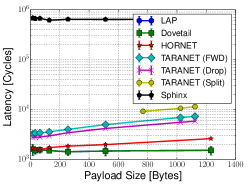
Processing latency
We first evaluate the average latency of processing a data packet on a single core using different anonymity protocols. For TARANET, we also compare the latency of performing different mutation actions. The results are shown in Figure 4(a).
TARANET’s processing latency is comparable to LAP, Dovetail, and HORNET. When the payload size is smaller than 64 bytes, processing a TARANET data packet (following the steps described above) incurs less than 1s (3700 cycles) per-hop overhead on a single core. For payloads larger than 1024 bytes, the latency increases to up to 2s (7200 cycles). Splitting a TARANET packet incurs only additional 1s (4200 cycles). Since the total number of ASes on a path is usually less than 7 [22], TARANET processing will add only 20s to the end-to-end latency.
Processing a setup packet on our test machine incurs around 250s (0.66M cycles) per hop per packet. This is due to setup packets requiring a DH key-exchange operation. However, for path lengths of less than 7 hops, this latency adds less than 2ms at the start of each flowlet.
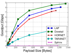
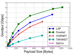
Goodput
Goodput measures the throughput of useful data that can be transmitted by the protocol as it separates data throughput and packet header overhead. Figures 4(b) and 4(c) show the goodput of different protocols with 7-hop and 14-hop headers, respectively, on a single 10 Gbps link with 1 core assigned. We observe that even with longer processing latency and larger headers, TARANET still achieves 45% of HORNET’s goodput in both cases. With a single core, TARANET can still achieve 0.37 Mpkt/s.
Maximum total throughput
To evaluate the maximum total throughput of our protocol with respect to the number of cores, we test TARANET with all twelve 10 Gbps ports enabled while using all 16 CPU cores. Each port has 1 input queue and 1 output queue. To fully distribute the computation power of 16 cores to 12 input and 12 output queues, we assign 8 cores exclusively to 8 input queues, 4 cores each to one input and one output queue, and the remaining 4 cores to 8 output queues. The packet generator generates packets that have random egress ports and saturate all 12 ports. Our evaluation finds that TARANET can process anonymous traffic at 50.96 Gbps on our software router for packets with 512 bytes of payload, which is comparable to the switching capacity of a commercial edge router [2].
Delay of flowlet setup
For the setup phase, TARANET uses packet batching and randomization to protect against traffic analysis. Our observation is that if the number of flowlet setups is sufficient large, batching setup packets can still end up yielding a short setup delay.
We conduct a trace-driven simulation using the CAIDA’s anonymized packet traces to evaluate the setup phase’s delay. The packet traces are recorded by the “equinix-chicago” monitor on a Tier-1 ISP’s 10 Gbps link between 1-2 pm on Mar. 20th, 2014 [11] We assume the first packet in each flow in the dataset is a flowlet setup packet. We simulate the latency introduced by batching, randomizing, and cryptographic processing by injecting the setup packet trace into a TARANET node and varying the batch size.
The resulting latency of flowlet setups increases almost linearly as the batch sizes increases. When the batch size is 16, the per-hop latency is 1.6 1.0 ms (95% confidence interval). When the batch sizes reaches 128, the per-hop latency increases up to 12 7 ms. For a path with 7 AS-hops that means the flowlet setup will introduce less than 170 ms additional round-trip latency for the setup phase, which is a small proportion of the delay of an inter-continental path.
7.3 Overhead Evaluation
We conduct a trace-based evaluation of TARANET to evaluate added bandwidth overhead for end hosts and the amount of state for routers. For bandwidth overhead, we evaluate the number of splittable packets required to accommodate different levels of packet drops and the number of chaff traffic needed to shape real-world traffic. We use CAIDA’s anonymized packet traces as discussed in Section 7.2. We filter away ICMP packets and small flows that has the size smaller than 10 packets or has the transmission rate lower than 1 byte/second.
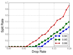
Split rate
First, we evaluate the number of splittable packets needed to account for packet drops. Note that an insufficient split rate causes a node to deplete its locally cached chaff and prematurely terminate a flowlet when there exist large number of packet drops. We convert each flow in the trace into flowlets where kbps and min and run the trace with different per-hop split rates, different drop rates, and various failure counters . We set to let a node to cache 3 chaff packets at maximum for each flowlet. Figure 5(a) shows the required per-hop split rates regarding different drop rates to achieve different success rates. The observed drop rate in the Internet is around 0.2% [61]. For such a low drop rate and a failure counter , a node can set the per-hop split rate to almost 0 and still obtain high success rates as much as 99%. To account for a highly lossy network link or an adversary that manipulates timing pattern through dropping packets, an end host can adjust the split rate up to 5% even for a very high per-hop drop rate 10% to achieve 95% success rates.
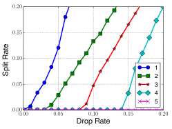
Figure 5(b) demonstrates the required per-hop split rates with respect to different drop rates to guarantee a 95% success rate when the failure counter ranges from 1 to 5. In general, given a certain packet drop rate, a larger helps reduce the per-hop split rate. For instance, when =1, the per-hop split rate can be as high as 12% for a packet drop rate of 5%. However, when increases to 2, the required per-hop split rate is already at 3.4%. When we lets =4, we can accommodate a per-hop drop rate of 15% by a per-hop split rate as small as 3.7%. We remark that when flowlets have smaller bandwidth (as will be shown next), the success rate increases.
Chaff overhead
We then evaluate the bandwidth overhead of the added chaff traffic. We convert real-world flows in the CAIDA’s packet traces into flowlets and compute the amount of chaff required. Note that we normalize the resulting overhead through dividing it by the total traffic volumes, in order to remove the impact of traffic volumes and network sizes.
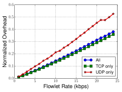
Figure 5(c) plots the chaff overhead needed for the conversion when the bandwidth parameter of flowlets varies and =1 min. Generally, large results in large chaff overhead. When we use =5 kbps, the overhead of chaff packets is 7%. In comparison, when becomes 20 kbps, the overhead of chaff traffic is increased to 31%. Moreover, we observe that small flow sizes, such as UDP flows for DNS lookups, lead to large chaff overhead given the same because more packets in the resulting flowlets are chaff packets. In Figure 5(c), the chaff overhead for UDP flows is larger than for TCP flows because the size of UDP flows is usually larger than the size of TCP flows.
Required amount of state and scalability
To enable traffic shaping for flowlets, an intermediate node maintains state bounded by the node’s bandwidth (Section 4.2). To demonstrate the scalability of TARANET with respect to the Internet traffic volumes, we evaluate the amount of state required for a node to process real Internet traffic.
For each flowlet that consumes bandwidth , a node maintains chaff packets and a failure counter required by the end-to-end traffic shaping technique (Section 4.2). We set and vary the bandwidth parameter for flowlets. Using the flowlets converted from our CAIDA flow trace, we can evaluate the amount of state required. Our results show that a node stores 90 MB state when =10 kbps for a 10 Gbps link and that the node needs to store 52 MB state when =20 kbps.
8 Discussion
8.1 Incremental Deployment
Deployment Incentives
We envision that ISPs have incentives to deploy TARANET to offer strong anonymity as a service to their privacy-sensitive users or other customer ISPs who in turn desire to offer anonymous communication services. This would give TARANET-deploying ISPs a competitive advantage: both private and business customers who want to use an anonymity service would choose an ISP that offers privacy protection.
Incremental Deployment Strategy
The minimal requirement for deploying TARANET includes a topology server that distributes path information, a few ISPs that deploy border routers supporting the TARANET protocol, and end hosts that run TARANET client software. We remark that the network architectures that we consider, such as NIRA [69], NEBULA [13] and SCION [70], already assume such topology servers as part of necessary control-plane infrastructure.
Admittedly, the more ISPs that deploy TARANET would increase the anonymity set size which in turn benefits all users. However, a few initial TARANET-enabled ISPs that share no physical links can establish tunnels between each other through legacy ISPs and start to carry anonymous traffic among users. As more TARANET-capable ISPs join the TARANET network, tunnels are increasingly replaced with direct ISP-to-ISP connections, which provides increasingly better guarantees.
8.2 Limitations
Long-term Intersection Attack
An adversary who observes presence of all sender and receiver clients over a long period of time can perform intersection analysis [26, 46] to reveal pairs of clients that are repeatedly online during the same period. Clients can minimize their risk by being online not only when they are actively communicating, but in general this attack is difficult to defend against through technical means. For further defenses, TARANET could be enhanced using existing solutions, such as dummy connections [15], or with the Buddies system [68], which allows clients to control which subset of pseudonyms appears online for a particular session. We leave analysis and evaluation of integration with such systems to future work.
Routing Attacks
TARANET relies on underlying network architectures for routing packets. Adversarial nodes can attack underlying network architectures to place themselves at strategic positions to launch traffic analysis [63, 60]. Although defeating routing attacks itself is beyond TARANET’s scope, the network architecture candidates we consider offer control and integrity of packets’ paths that prevent routing attacks. For example, SCION [70] and NEBULA [13] both embed integrity tags within paths to prevent path modification. Pathlet [32] pushes path selection to end hosts, enabling end hosts to select the traversing path.
Denial-of-Service Attacks
An adversary can initiate a high volume of flowlets passing through a node, to exhaust the node’s computation power, bandwidth, and memory. TARANET itself cannot defend against such a DoS attack. To mitigate the DoS attack, a node can require flowlet initiators to solve cryptographic puzzles [26]. Additionally, an ISP that operates TARANET can also directly restrict the average flowlet-initiation rate of its customers. We note that a DoS attack aiming to exhaust a TARANET’s memory state by initiating large number of flowlets will fail, because the amount of state that a TARANET node maintains is strictly linear to the node’s actual bandwidth. If the adversary is able to accumulate sufficient bandwidth, such an attack will only jam the network link of the victim node and become a bandwidth-based DoS attack that can be mitigated.
9 Conclusion
In this paper, we have shown that it is possible to obtain the efficiency of onion-routing-based anonymity systems and the security of mix-based systems while avoiding their disadvantages. We have designed TARANET, which uses mixing and coordinated traffic shaping to thwart traffic analysis for the setup phase and the data transmission phase respectively. To achieve high performance and scalability, we build on the key observation that high-speed networks process enough volume that mixing at their core routers has minimal performance overhead. The performance and security properties achieved by our protocol suggest that efficient traffic-analysis-resistant protocol at the network layer is feasible, and that the increased security warrants the additional performance cost.
10 Acknowledgments
We would like to thank the anonymous reviewers for their suggestions for improving the paper. We also appreciate the insightful discussion with the members of ETH Zurich Network Security group.
The research leading to these results has received funding from the European Research Council under the European Union’s Seventh Framework Programme (FP7/2007-2013) / ERC grant agreement 617605. We gratefully acknowledge support from ETH Zurich and from the Zurich Information Security and Privacy Center (ZISC).
References
- [1] CAIDA AS-relationship dataset. http://www.caida.org/data/as-relationships/.
- [2] Cisco ASR-1000. http://www.cisco.com/c/en/us/products/routers/asr-1000-series-aggregation-services-routers/index.html.
- [3] curve25519-donna. https://code.google.com/p/curve25519-donna/.
- [4] DPDK: Data Plane Development Kit. http://dpdk.org/.
- [5] Intel AESNI Sample Library. https://software.intel.com/en-us/articles/download-the-intel-aesni-sample-library.
- [6] iPlane dataset. http://iplane.cs.washington.edu/data/data.html.
- [7] PolarSSL. https://polarssl.org/.
- [8] Routeview project. http://www.routeviews.org/.
- [9] Segment routing architecture (IETF draft). https://datatracker.ietf.org/doc/draft-ietf-spring-segment-routing/. Retrieved on January 27, 2016.
- [10] Spirent TestCenter. http://www.spirent.com/~/media/Datasheets/Broadband/PAB/SpirentTestCenter/STC_Packet_Generator-Analyzer_BasePackage_datasheet.pdf.
- [11] The CAIDA UCSD Anonymized Internet Traces 2014. http://www.caida.org/data/passive/passive_2014_dataset.xml.
- [12] Tor metrics: Direct users by country. ”https://metrics.torproject.org/userstats-relay-country.html. Retrieved on Nov.3, 2015.
- [13] Tom Anderson, Ken Birman, Robert Broberg, Matthew Caesar, Douglas Comer, Chase Cotton, Michael J Freedman, Andreas Haeberlen, Zachary G Ives, Arvind Krishnamurthy, et al. The nebula future internet architecture. In The Future Internet, pages 16–26. Springer, 2013.
- [14] Oliver Berthold, Hannes Federrath, and Stefan Köpsell. Web mixes: A system for anonymous and unobservable internet access. In PETS, 2001.
- [15] Oliver Berthold and Heinrich Langos. Dummy Traffic against Long Term Intersection Attacks. In PETS, 2003.
- [16] Avrim Blum, Dawn Song, and Shobha Venkataraman. Detection of interactive stepping stones: Algorithms and confidence bounds. In Recent Advances in Intrusion Detection. Springer, 2004.
- [17] Jan Camenisch and Anna Lysyanskaya. A formal treatment of onion routing. In CRYPTO, 2005.
- [18] Sambuddho Chakravarty, Marco V. Barbera, Georgios Portokalidis, Michalis Polychronakis, and Angelos D. Keromytis. On the effectiveness of traffic analysis against anonymity networks using flow records. In PAM, 2014.
- [19] Sambuddho Chakravarty, Angelos Stavrou, and Angelos D Keromytis. Traffic analysis against low-latency anonymity networks using available bandwidth estimation. In ESORICS, 2010.
- [20] David Chaum. The dining cryptographers problem: Unconditional sender and recipient untraceability. Journal of cryptology, 1(1), 1988.
- [21] David L Chaum. Untraceable electronic mail, return addresses, and digital pseudonyms. Communications of the ACM, 24(2), 1981.
- [22] Chen Chen, Daniele E. Asoni, David Barrera, George Danezis, and Adrian Perrig. HORNET: High-speed onion routing at the network layer. In ACM CCS, 2015.
- [23] Benny Chor, Oded Goldreich, Eyal Kushilevitz, and Madhu Sudan. Private information retrieval. Journal of the ACM, 45(6), 1998.
- [24] George Danezis. The traffic analysis of continuous-time mixes. In PETS, 2004.
- [25] George Danezis and Ian Goldberg. Sphinx: A compact and provably secure mix format. In IEEE S&P, 2009.
- [26] George Danezis and Andrei Serjantov. Statistical disclosure or intersection attacks on anonymity systems. In IH, 2005.
- [27] Debajyoti Das, Sebastian Meiser, Esfandiar Mohammadi, and Aniket Kate. Anonymity trilemma: Strong anonymity, low bandwidth overhead, low latency—choose two. In IEEE S&P, 2018.
- [28] Roger Dingledine, Nick Mathewson, and Paul Syverson. Tor: The second-generation onion router. In USENIX Security, 2004.
- [29] Roger Dingledine and Steven J. Murdoch. Performance Improvements on Tor or, Why Tor is slow and what we’re going to do about it. ”http://www.torproject.org/press/presskit/2009-03-11-performance.pdf, 2009. Retrieved on May. 23, 2016.
- [30] Nathan S Evans, Roger Dingledine, and Christian Grothoff. A practical congestion attack on tor using long paths. In USENIX Security, 2009.
- [31] Michael J Freedman and Robert Morris. Tarzan: A peer-to-peer anonymizing network layer. In ACM CCS, 2002.
- [32] P Godfrey, Igor Ganichev, Scott Shenker, and Ion Stoica. Pathlet routing. ACM SIGCOMM CCR, 39(4), 2009.
- [33] Philippe Golle and Ari Juels. Dining cryptographers revisited. In Eurocrypt, 2004.
- [34] Xun Gong, Nikita Borisov, Negar Kiyavash, and Nabil Schear. Website Detection Using Remote Traffic Analysis. In PETS, 2012.
- [35] Nicholas Hopper, Eugene Y. Vasserman, and Eric Chan-Tin. How much anonymity does network latency leak? ACM TISSEC, 2010.
- [36] Amir Houmansadr and Nikita Borisov. SWIRL: A Scalable Watermark to Detect Correlated Network Flows. In NDSS, 2011.
- [37] Amir Houmansadr and Nikita Borisov. The need for flow fingerprints to link correlated network flows. In PETS, 2013.
- [38] Amir Houmansadr, Negar Kiyavash, and Nikita Borisov. RAINBOW: A robust and invisible non-blind watermark for network flows. In NDSS, 2009.
- [39] Hsu Chun Hsiao, Tiffany Hyun Jin Kim, Adrian Perrig, Akira Yamada, Samuel C. Nelson, Marco Gruteser, and Wei Meng. LAP: Lightweight anonymity and privacy. In IEEE S&P, 2012.
- [40] Marc Juarez, Sadia Afroz, Gunes Acar, Claudia Diaz, and Rachel Greenstadt. A critical evaluation of website fingerprinting attacks. In ACM CCS, 2014.
- [41] Stevens Le Blond, David Choffnes, William Caldwell, Peter Druschel, and Nicholas Merritt. Herd: A scalable, traffic analysis resistant anonymity network for VoIP systems. In ACM SIGCOMM, 2015.
- [42] Stevens Le Blond, David Choffnes, Wenxuan Zhou, Peter Druschel, Hitesh Ballani, and Paul Francis. Towards Efficient Traffic-analysis Resistant Anonymity Networks. In ACM SIGCOMM, 2013.
- [43] Taeho Lee, Christos Pappas, Adrian Perrig, Virgil Gligor, and Yih-Chun Hu. The case for in-network replay suppression. In ACM AsiaCCS, 2017.
- [44] Brian N Levine, Michael K Reiter, Chenxi Wang, and Matthew Wright. Timing attacks in low-latency mix systems. In FC. Springer, 2004.
- [45] Brian N. Levine, Michael K. Reiter, Chenxi Wang, and Matthew K. Wright. Timing attacks in low-latency mix-based systems. In FC, 2004.
- [46] Nick Mathewson and Roger Dingledine. Practical traffic analysis: Extending and resisting statistical disclosure. In PETS, 2005.
- [47] Prateek Mittal, Ahmed Khurshid, Joshua Juen, Matthew Caesar, and Nikita Borisov. Stealthy traffic analysis of low-latency anonymous communication using throughput fingerprinting. In ACM CCS, 2011.
- [48] Prateek Mittal, Ahmed Khurshid, Joshua Juen, Matthew Caesar, and Nikita Borisov. Stealthy traffic analysis of low-latency anonymous communication using throughput fingerprinting. In ACM CCS, 2011.
- [49] Steven J Murdoch. Hot or not: Revealing hidden services by their clock skew. In ACM CCS, 2006.
- [50] Steven J. Murdoch and George Danezis. Low-cost traffic analysis of Tor. In IEEE S&P, 2005.
- [51] Steven J Murdoch and Piotr Zieliński. Sampled traffic analysis by internet-exchange-level adversaries. In PETS, 2007.
- [52] Lasse Overlier and Paul Syverson. Locating hidden servers. In IEEE S&P, 2006.
- [53] Andreas Pfitzmann and Marit Köhntopp. Anonymity, unobservability, and pseudonymity - a proposal for terminology. In PETS, 2001.
- [54] Ania Piotrowska, Jamie Hayes, Tariq Elahi, Sebastian Meiser, and George Danezis. The loopix anonymity system. In Usenix Security, 2017.
- [55] Ryan Pries, Wei Yu, Xinwen Fu, and Wei Zhao. A new replay attack against anonymous communication networks. In ICC’08, pages 1578–1582. IEEE, 2008.
- [56] Felix Putze, Peter Sanders, and Johannes Singler. Cache-, hash- and space-efficient bloom filters. In Workshop on Experimental Algorithms, 2007.
- [57] Jody Sankey and Matthew Wright. Dovetail: Stronger anonymity in next-generation internet routing. In PETS, 2014.
- [58] Rob Sherwood, Bobby Bhattacharjee, and Aravind Srinivasan. P5: A protocol for scalable anonymous communication. In IEEE S& P, 2002.
- [59] Vitaly Shmatikov and Ming-Hsiu Wang. Timing analysis in low-latency mix networks: Attacks and defenses. In ESORICS. Springer, 2006.
- [60] Yixin Sun, Anne Edmundson, Laurent Vanbever, Oscar Li, Jennifer Rexford, Mung Chiang, and Prateek Mittal. Raptor: routing attacks on privacy in tor. In USENIX Security 15, 2015.
- [61] Srikanth Sundaresan, Walter de Donato, Nick Feamster, Renata Teixeira, Sam Crawford, and Antonio Pescapè. Broadband Internet performance: a view from the gateway. In ACM SIGCOMM, 2011.
- [62] Paul Syverson, Gene Tsudik, Michael Reed, and Carl Landwehr. Towards an analysis of onion routing security. In PETS, 2001.
- [63] Laurent Vanbever, Oscar Li, Jennifer Rexford, and Prateek Mittal. Anonymity on quicksand: Using bgp to compromise tor. In ACM HotNet, 2014.
- [64] Tao Wang, Xiang Cai, Rishab Nithyanand, Rob Johnson, and Ian Goldberg. Effective attacks and provable defenses for website fingerprinting. In USENIX Security, 2014.
- [65] Wei Wang, Mehul Motani, and Vikram Srinivasan. Dependent link padding algorithms for low latency anonymity systems. In CCS. ACM, 2008.
- [66] Xinyuan Wang and Douglas S. Reeves. Robust correlation of encrypted attack traffic through stepping stones by manipulation of interpacket delays. In ACM CCS, 2003.
- [67] David Isaac Wolinsky, Henry Corrigan-Gibbs, Bryan Ford, and Aaron Johnson. Dissent in numbers: Making strong anonymity scale. In Usenix OSDI, 2012.
- [68] David Isaac Wolinsky, Ewa Syta, and Bryan Ford. Hang with your buddies to resist intersection attacks. In ACM CCS, 2013.
- [69] Xiaowei Yang, David Clark, and Arthur W Berger. NIRA: a new inter-domain routing architecture. IEEE/ACM TON, 15(4), 2007.
- [70] Xin Zhang, Hsu-Chun Hsiao, Geoffrey Hasker, Haowen Chan, Adrian Perrig, and David G. Andersen. SCION: Scalability, control, and isolation on next-generation networks. In IEEE S&P, 2011.
- [71] Yin Zhang and Vern Paxson. Detecting stepping stones. In USENIX Security, 2000.
- [72] Ye Zhu, Xinwen Fu, Bryan Graham, Riccardo Bettati, and Wei Zhao. On flow correlation attacks and countermeasures in mix networks. In PET, 2004.