Dynamic Sealing Using Magneto-Rheological Fluids
Abstract
Micropumps are microfluidic components which are widely used in applications such as chemical analysis, biological sensing and micro-robots. However, one obstacle in developing micropumps is the extremely low efficiency relative to their macro-scale counterparts. This paper presents a dynamic sealing method for external gear pumps to reduce the volumetric losses through the clearance between the tips of gears and the housing by using magneto-rheological (MR) fluids. By mitigating these losses, we are able to achieve high efficiency and high volumetric accuracy with current mechanical architectures and manufacturing tolerances. Static and dynamic sealing using MR fluids are investigated theoretically and experimentally. Two Mason numbers and which are defined in terms of pressure gradient of the flow and velocity of the moving boundary respectively are used to characterize and evaluate the sealing performance. A range of magnetic field intensities is explored to determine optimal sealing effectiveness, where effectiveness is evaluated using the ratio of volumetric loss and friction factor. Finally, we quantify the effectiveness of this dynamic sealing method under different working conditions for gear pumps.
I Introduction
Micropumps are miniaturized pumping devices that are usually manufactured by MEMS micromachining technologies abhari2012comprehensive ; tay2002microfluidics . In recent years, the target applications have expanded owing to the integration of novel physical principles and the invention of new fabrication methods. Micropumps are commonly used in chemical analyses, biological sensing, drug delivery and micro-robots junwu2005design ; cui2007study ; lintel1988piezoelectric .
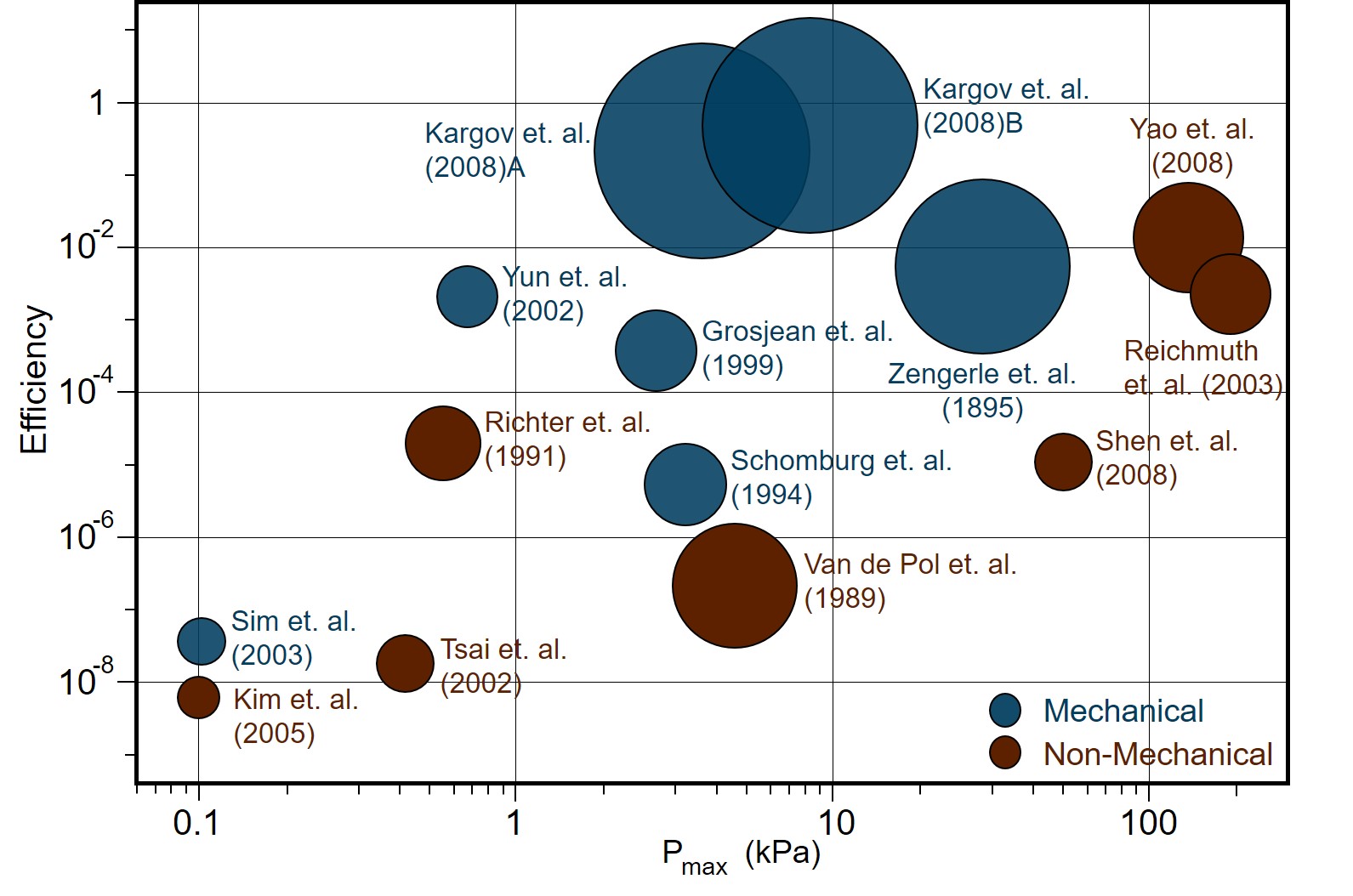
Unfortunately, miniaturization comes at a cost and nearly all micropumps suffer from low efficiency. The reported efficiencies of the available micropump technologies are shown in Fig. 1. Typically, the overall efficiency of a micropump is determined by a combination of four components: volumetric efficiency, hydraulic efficiency, mechanical efficiency and electrical efficiency. Out of these four, volumetric losses and hydraulic losses dominate at small scales. As the size of the system decreases, the volumetric efficiency decreases since the same dimensional and geometric tolerances result in a larger fractional loss. Furthermore, in terms of hydraulic efficiency, the Reynolds number decreases as the systems size decreases, resulting in larger viscous losses.
For external gear pumps, the volumetric losses are roughly proportional to the pressure gradient assuming a quasi-steady fully developed low Reynolds number flow across the clearance between the housing and the gear tips dopper1997micro . Thus, the effeciency may be extremely low when the pump is operating under high pressure gradient conditions. The volumetric leakage between the tips of the gears and across the side plates is typically considered to comprise the largest proportion of the total efficiency loss in external gear pumps totten2011handbook ; merritt1967hydraulic . Various end wear plates have been studied and designed to reduce the leakage across the side plates hooke1984end . However, studies that consider volumetric losses between the tip of the gear teeth and the housing are relatively rare. Sealing is even more challenging for micro-scale gear pumps due to the limits of manufacturing precision. With precise manufacturing techniques and tight tolerances, the volumetric loss could be reduced. But in that case the mechanical friction between the housing and the gears will increase and small clearances may also make the pump more vulnerable to vibrations. Therefore, we propose to develop a dynamic sealing method using magneto-rheological (MR) fluids that can operate with the current mechanical architectures and manufacturing tolerances.
Magnetorheological (MR) fluids are materials that exhibit a reversible change in rheological properties with the application of an external magnetic field, which can result in a rich range of physical properties furst1998particle ; tao1998structural ; zhu1996role ; jolly1999properties . In engineering applications, they were initially used by Jacob Rabinow in the design of a clutch in the late 1940s goncalves2006review . In more recent years, MR fluids have found further applications and commercial success ginder1996rheology . Typical operational modes for MR fluid application are the pressure driven flow mode and the direct shear mode tao1998structural ; jolly1999properties . The most common application is a mechanical damper, which yields appealing features such as low-power consumption, force controllability and rapid response lee2000control ; kwok2007bouc . In particular, automotive dampers with these properties have been widely investigated lee2000control ; kim1999vibration ; sassi2005innovative . The other common use of MR fluids is the development of MR valves. In addition, high efficiency, miniaturized MR valves have been achieved yoo2002design ; guo2003finite .
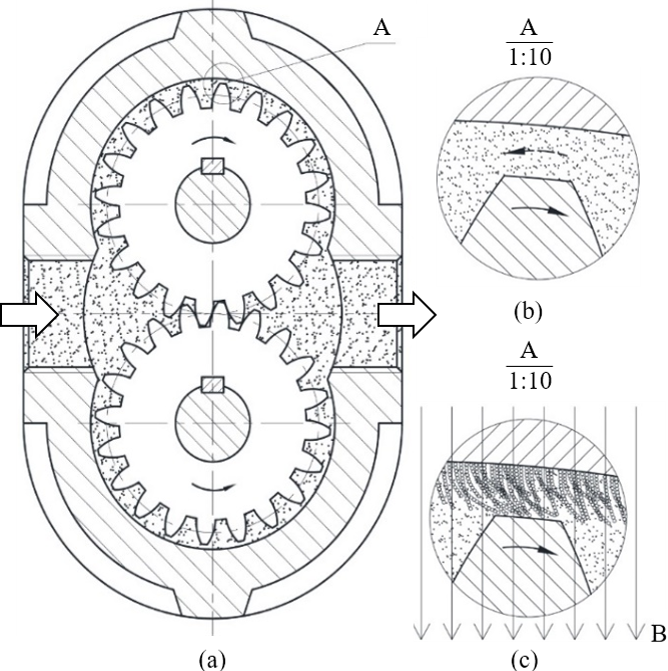
A schematic of a typical external gear pump is shown in Fig. 2. The pressure of the outlet is larger than that of inlet, resulting in back-flow aross the gap between the tips of the gears and the pump housing, as shown in Fig. 2 (b). Meanwhile in Fig. 2 (c), subjecting MR fluid to an external magnetic field causes magnetic-induced dipoles to aggregate in the vicinity of the housing, which prevents the back-flow. This design have the potential to dispense of precise manufacturing and solve the challenge of controlling the clearance between the housing and gear tips.
Previous research primarily focused on MR fluids in either Couette flow or Poiseuille flow, usually within the scope of high shear stress which arises from either a large pressure differential or large exerted force jolly1999properties ; goncalves2006review ; ginder1996rheology ; tao1998structural ; jolly1999properties ; kwok2007bouc ; lee2000control ; kim1999vibration ; sassi2005innovative ; yokota1999pressure ; yoo2002design ; guo2003finite . By contrast, much less is known about the physics of MR fluids subject to the combination of Couette and Poiseuille flow. In this study, we investigate the performance of dynamic seals of MR fluid chains subject to shear-driven flows from gear motion and simultaneously to pressure-driven flows from back-flow. We compare experimental results to a model which incorporates two dimensionless Mason numbers, one from Couette flow and one from Poiseuille flow.
II Method
II.1 Experiments for MR Fluid in Poiseuille Flow or Couette Flow
In order to visualize the effect of Poiseuille flow on the morphology of the MR chains, we designed a experimental system specialized for visualization. We built a micro-channel network made of a silicon slide, which is laser-cut and sandwiched between two transparent acrylic plates. MR fluid is from Lord. The volume fraction of MR particles is diluted to be 1%. The flow was driven by a pressure gradient using a syringe pump to control the flow rate. Typical deformations in the channel for different flow rates are displayed in Fig. 3 (Top). The images suggest that the deformation of the magnetic chains increases as flow rate increases until the magnetic chains finally collapse. Note that with low flow rate, magnetic chains tend to aggregate in bunches with very little deformation. These chains appear to attach in the vicinity of the walls of the channel. As the flow rate increases, the chains are more clearly deformed and segregated.
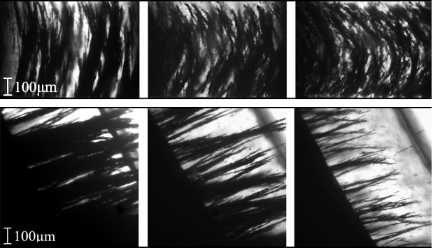
To observe the deformation of MR chains under Couette flow, we built another experimental system. We run the experiments without an adverse pressure gradient. Results are shown in Fig. 3 (Bottom); the left black area of each figure depicts a roughened stationary surface, and the black line on the upper right depicts the surface of the disk. As the rotational speed increases, the density of magnetic brushes decreases with a larger curvature.
II.2 Experiments for MR Fluid in Poiseuille-Couette Flow
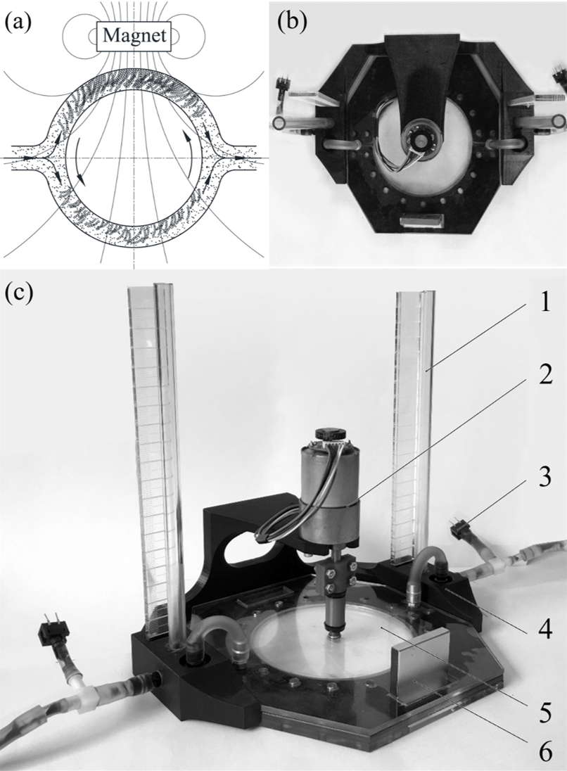
To model the interaction between the gear tooth and the housing, we built a simplified experimental system, as shown in Fig. 4. Panel (a) depicts a schematic of the underlying design, where fluid enters the inlet on the left, then bifurcates into two slots. The slot is used to mimic the clearance between the tip of the gears and the housing. A rotating disk is utilized to mimic one gear tooth.
Fig. 4 (b) and (c) show snapshots of the experimental model system, which mainly consists of frame, motor, disk, pitot tube, magnet and pressure sensor. The frame, which designed to secure other components, contains a cavity, which connects the tube fitting, the pitot tube and the tube connected to the slots in the middle. A laser cut acrylic disk, driven by the motor, is sandwiched between two transparent plates with slots to locate the magnet. The carrier fluid of the MR fluids is silicone oil (Gelest, 100 cSt). MR fluid is from Lord. The volume fraction of MR particles is diluted to be 10%. The magnets have a surface field of 1895 Gauss (NdFeB, Grade N42, 2.44 oz.).
We used a variable voltage power supply to power both the sensors and the motor (Pololu 12 V), using voltages of 10.5 V and from 0 V to 40 V respectively. Pressure data acquired from the sensors were sent to Labview via National Instruments I/O. Motor speed was acquired from the encoder of the motor and sent to the Arduino built-in serial monitor via Arduino Uno.
III Results and Discussion
III.1 Model for MR Fluid in Poiseuille-Couette Flow
The experimental setup, shown in Fig. 4, can be modeled as two slots in parallel in the presence of different magnetic field intensity. A schematic of one slot is shown in Fig. 5. This half can be simplified as a straight channel with the reference frame attached shown in the partial enlarged view in Fig. 5, based on the fact that the aspect ratio mm50 mm . Thus, we consider two straight slots in parallel. The theoretical results are calculated numerically to account for the square channel cross-section rowe1970measurements . The Reynolds number , so the inertia of the MR fluid is negligible.
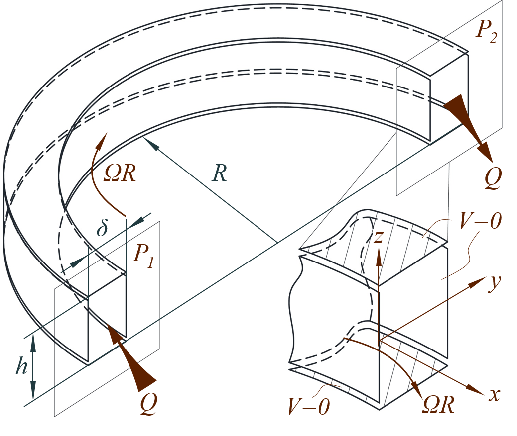
The flow is driven by both a pressure gradient and a moving wall. In the limit of low Reynolds number, the conservation of momentum equation for steady, laminar flow, in the -direction, reduces to:
where is the mechanical pressure, is the shear stress.
The MR fluid is modeled as a Bingham fluid in this paper. Due to the distribution of magnetic field intensity, the yield stress is larger in the slot closer to the magnet than that in the further one. The constitutive relationship can be expressed as:
| ; | ||||
| ; |
where is the viscosity of the MR fluid, is the yield stress, and is the shear rate.
We furthermore have the following boundary conditions on the inner and outer walls of the channel:
where is the velocity of the fluid in -direction and is the velocity of the inner wall.
To characterize the behavior of the dipole chains, we use the Mason number, which has been commonly considered in prior studies melle2003microstructure ; du2016modified ; van2014microfluidics ; becnel2014mason . In our study, we define two Mason numbers: one which is the ratio between the shear forces and the magnetic interaction forces in Poiseuille flow, and another one for Couette flow. The magnetic interaction forces are characterized by the yield stress becnel2015nondimensional ; sherman2015relating .
To non-dimensionlize the governing equation, the other dimensionless variables are defined as follows:
Substituting the dimensionless variables into the conservation of momentum equation and the constitutive equation yields:
| ; | ||||
| ; | ||||
| ; |
The boundary conditions become:
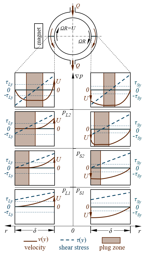
The velocity profiles can be computed from the governing equation and the associated boundary conditions, and can be categorized into three modes: (i) a one-region mode, (ii) a two-region mode and (iii) a three-region mode gjerstad2012simplified ; liu2010axial . (i) The one-region mode occurs when the pressure gradient is small and the velocity of the boundary is relatively large. The fluid stress is larger than the yield stress of the Bingham fluid across the entire slot, so MR chains cannot form. The velocity profile in the one-region mode is identical to that of a Newtonian fluid in Poiseuille-Couette flow. (ii) The two-region mode occurs as the pressure gradient increases, which increases the slope of the stress distribution. In the region where the fluid stress is smaller than the yield stress, a plug zone will occur, where MR chains form and the velocity profile resembles plug flow. In two-region mode, the plug zone is anchored to the surface nearest the magnet, whereas in the region at the opposing surface the MR particles are prevented from aggregating, similarly to one-region mode. (iii) Finally, the three-region mode occurs as the pressure gradient increases even further. Under such conditions, the plug zone will detach from the wall and move to the middle of the channel, surrounded by Newtonian regions on either side. Considering these three types of modes for the two slots in our experimental study, there are four possible combinations of velocity profiles in this study, as shown in Fig. 6. The slot closest to the magnet is in the presence of a higher magnetic field, resulting in a larger yield stress . In our study, is about four times larger than .
The average velocity of the fluid in the one-region mode is given by:
The average velocity of the fluid in the two-region mode depends on the sign of and . When has the same sign as , we have:
and when has the opposite sign to , we have:
The average velocity of the fluid in the three-region mode is given by:
The transition pressure from one-region mode to two-region mode and from two-region mode to three-region mode can also be computed and are found to be quantities and respectively:
| (1) | |||||
| (2) |
III.2 Experimental Results for MR Fluid in Poiseuille-Couette Flow
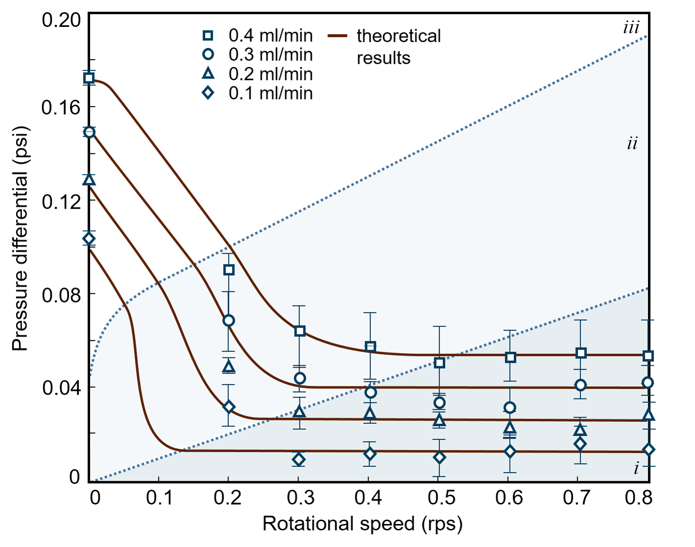
We investigate the performance of the dynamic seals using the experimental setup shown in Fig. 4 (b). The flow rate is controlled by a syringe pump, ranging from 0.1 ml/min to 0.8 ml/min. For each given flow rate, the rotational speed of the motor is varied from 0 rps to 0.8 rps. The pressure differential is given by two pressure sensors located at the inlet and outlet. The results are shown in Fig. 7 (a). As the rotational speed increases, the pressure differential decreases abruptly from the static state to the dynamic state, and settles to a steady state.
We apply numerical methods to calculate the velocity profile in the rectangular cross-section, and integrate the velocity profile in the cross-section to get the total flow rate. We first consider Couette flow as a simple example. In the case of two parallel infinite plates, the velocity decreases linearly away from the moving wall. In the real experimental setup, as shown in Fig. 4 and Fig. 5, the aspect ratio mm mm with a clearance 0.127 mm due to the gasket for sealing. The ratio of the average velocity of the real case to that of the Couette case is . Pressure losses between the sensors and the inlet and outlet have been taken into account. In our experiments, a significant pressure loss occurs due to the Poiseuille flow between the sensors and the inlet and outlet, four 90-elbows and the cavities which connects the pitot tube and the two tubings. The distance between the pressure sensor and the outlet is mm; the inner diameter of the tube is mm. The Reynolds number , so inertial effects are negligible. For elbows, the pressure loss is estimated from empirical equation. For 90-elbow curved, the equivalent length is menon2004piping .
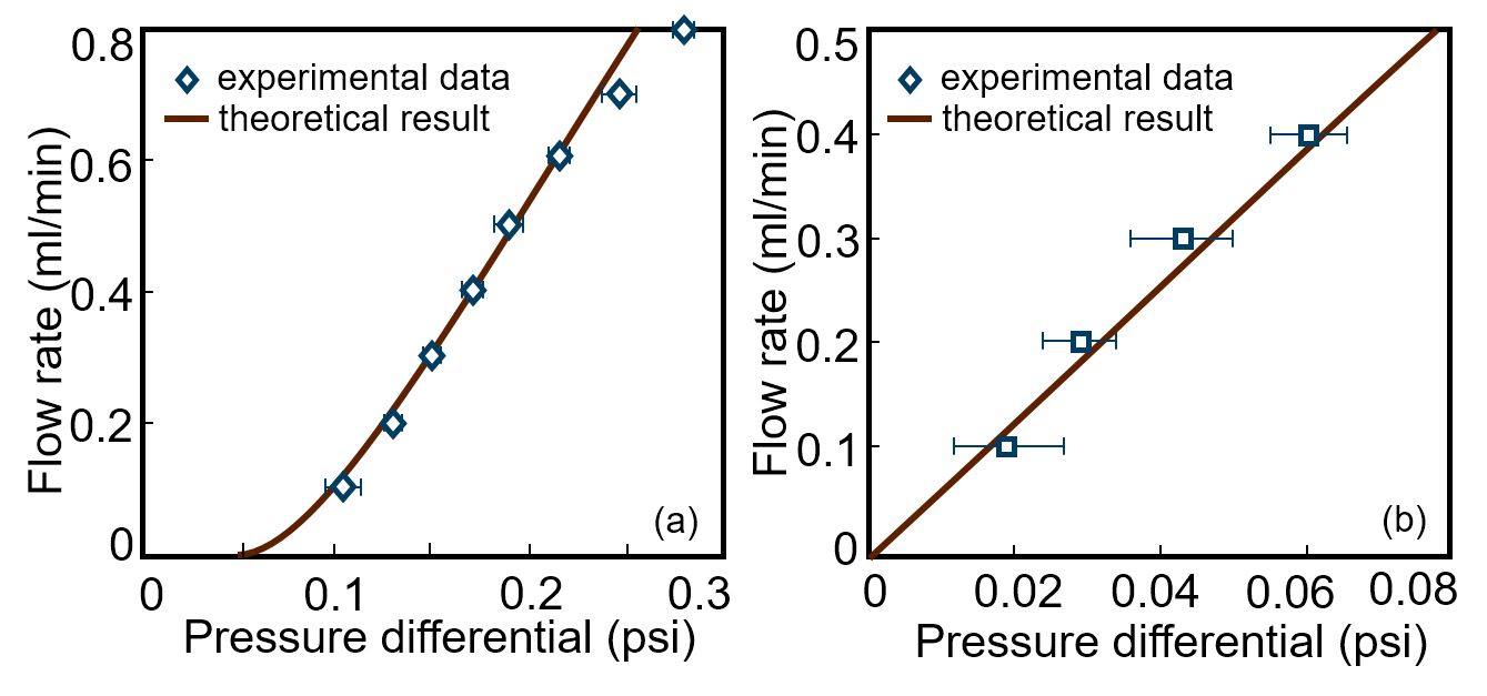
Our mathematical Bingham model of MR fluid agrees well with the experimental results, as shown in Fig. 8. One limiting condition is when the rotational speed is zero, which corresponds to the classic Poseuille flow for Bingham fluid. In our experiment, this condition can be treated as two slots for Bingham Poiseuille flow in parallel with different yield stresses (Fig. 8 (a)). The other limiting condition is that the rotational speed of the disk is fast enough so that the flow in both slots are in the one-region mode. Thus, the velocity profile of MR fluid is identical as that of Poiseuille-Couette flow of a Newtonian fluid. Because the directions of the Couette flow are opposite in the parallel slots, the flow rate induced by Couette flow is actually canceled out. Thus, the flow rate as a function of pressure gradient is linear, as shown in Fig. 8 (b).
III.3 Optimal Magnetic Field Intensity
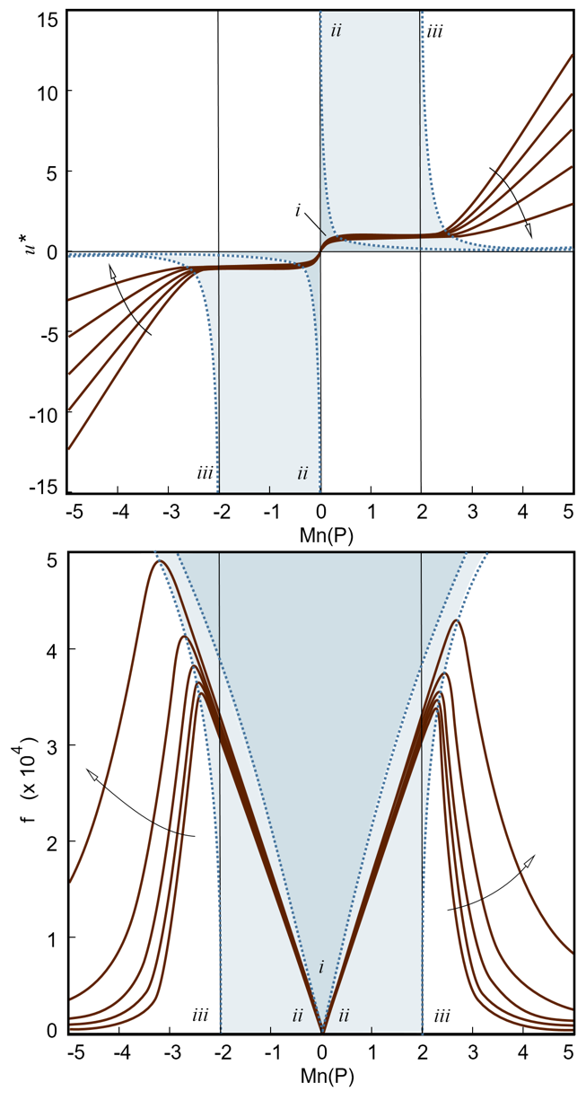
In terms of the design and application for external gear pumps, we consider two performance metrics which evaluate the performance of dynamic seals. The first performance metric is given by the ratio of volumetric flow rate loss to the nominal volumetric flow rate of the gear pump. The nominal volumetric flow rate is proportional to the angular speed of the gear. Therefore, the dimensionless group can be used to characterize the sealing effectiveness of MR fluid, where is the average velocity of the back-flow rate in the clearance of the gear pump, is proportional to the volumetric flow rate pumped by the gear pump. As shown in Fig. 9 (a), to achieve higher effectiveness, should be designed to be as small as possible. is the transition point of the velocity profile from one-region mode to two-region mode for both slots, because equals . , are the transition points of the velocity profile from two-region mode to three-region mode for the slots in the presence of larger and smaller magnetic field intensity respectively. We find that when is larger than , dramatically increases. Thus, to ensure a small volumetric loss, should be smaller than .
The second performance metric comes from the energy loss in both of the slots, which can be characterized by the friction factor . To achieve the optimal sealing performance, the friction factor needs to be maximized, indicating that the back-flow between the gear teeth and the housing will experience as much energy loss as possible. As shown in Fig. 9 (b), the maximum friction factor can be achieved around , which is the of the transition point from two-region mode to three-region mode for the slot in presence of the smaller magnetic field intensity.
Upon considering the two performance metrics mentioned above, the optimal sealing performance can be achieved at the transition of two-region mode to three-region mode. Thus, at any given nominal work condition of external gear pump, the magnetic field intensity can be tuned to make the yield stress satisfy Eq. (2), which can be expressed explicitly by the following equation:
The relationship between magnetic field intensity () and yield stress () of MR fluid has been studied in prior studies: jolly1999properties
where is the magnetic field intensity, is the yield stress.
We define a ratio as a metric for the effectiveness of dynamic seals using MR fluid:
where is the volumetric loss using general pump oil, is the volumetric loss using MR fluid with the same viscosity as the general pump oil.
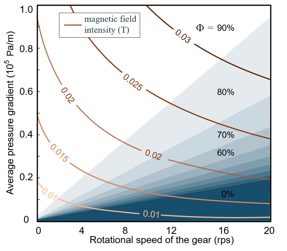
The optimal magnetic field intensity is shown in Fig. 10. It suggests that dynamic sealing using rheological fluid will achieve the optimal sealing effectiveness under a high pressure gradient and relatively low rotational speed, which would reduce the volumetric loss to over 90%.
IV conclusion
Volumetric loss accounts for the extremely low efficiency of small-scale gear pumps. In order to reduce the volumetric loss without introducing larger friction, tighter manufacturing tolerances, or vulnerability to vibrations, we introduced a method where magnetorheological fluid is activated in the vicinity of the clearance between gear and housing to create a dynamic seal.
We verified the Bingham fluid model for MR fluids, and have accounted for the combined Poiseuille-Couette flow at low Reynolds number in the application of sealing in external gear pumps. We furthermore found four possible combinations of the velocity profiles given by two modified Mason numbers and .
We determined the dependence of optimal magnetic field intensity on the pressure gradient and rotational speed of the gear. The optimal magnetic field intensity corresponds to the transition for the velocity profile of MR fluid to transit from three-region mode to two-region mode. Our dynamic sealing method using MR fluid reduces volumetric loss above 90% when the pressure gradient is large; that is, when the hydraulic actuation system is under heavy load at low speed. Besides application for reducing the volumetric loss in the clearance, our method can also be applied for reducing the loss between the housing and the sides of gears for all types of gear pumps.
Acknowledgements.
A.E.H. acknowledges support from the Defense Advanced Research Projects Agency under grant number DARPA W31P4Q-13-1-0013. We gratefully thank Marie Baumier for insightful discussions.References
- (1) Farideh Abhari, Haslina Jaafar, and Nurul Amziah Md Yunus. A comprehensive study of micropumps technologies. Int. J. Electrochem. Sci, 7:9765–9780, 2012.
- (2) Francis EH Tay. Microfluidics and BioMEMS applications. Springer, 2002.
- (3) Kan Junwu, Yang Zhigang, Peng Taijiang, Cheng Guangming, and Wu Boda. Design and test of a high-performance piezoelectric micropump for drug delivery. Sensors and Actuators A: Physical, 121(1):156–161, 2005.
- (4) Qifeng Cui, Chengliang Liu, and Xuan F Zha. Study on a piezoelectric micropump for the controlled drug delivery system. Microfluidics and Nanofluidics, 3(4):377–390, 2007.
- (5) HTG van Lintel, FCM Pol, and S Bouwstra. A piezoelectric micropump based on micromachining of silicon. Sensors and actuators, 15(2):153–167, 1988.
- (6) Woo Young Sim, Hyeun Joong Yoon, Ok Chan Jeong, and Sang Sik Yang. A phase-change type micropump with aluminum flap valves. Journal of Micromechanics and Microengineering, 13(2):286, 2003.
- (7) Ki Hoon Kim, Hyeun Joong Yoon, Ok Chan Jeong, and Sang Sik Yang. Fabrication and test of a micro electromagnetic actuator. Sensors and Actuators A: Physical, 117(1):8–16, 2005.
- (8) Kwang-Seok Yun, Il-Joo Cho, Jong-Uk Bu, Chang-Jin Kim, and Euisik Yoon. A surface-tension driven micropump for low-voltage and low-power operations. Journal of microelectromechanical systems, 11(5):454–461, 2002.
- (9) A Richter, A Plettner, KA Hofmann, and H Sandmaier. A micromachined electrohydrodynamic (ehd) pump. Sensors and Actuators A: Physical, 29(2):159–168, 1991.
- (10) Jr-Hung Tsai and Liwei Lin. A thermal-bubble-actuated micronozzle-diffuser pump. Journal of microelectromechanical systems, 11(6):665–671, 2002.
- (11) A Kargov, T Werner, C Pylatiuk, and S Schulz. Development of a miniaturised hydraulic actuation system for artificial hands. Sensors and Actuators A: Physical, 141(2):548–557, 2008.
- (12) Xing Yang, Charles Grosjean, and Yu-Chong Tai. Design, fabrication, and testing of micromachined silicone rubber membrane valves. Journal of microelectromechanical systems, 8(4):393–402, 1999.
- (13) R Rapp, WK Schomburg, D Maas, J Schulz, and W Stark. Liga micropump for gases and liquids. Sensors and Actuators A: Physical, 40(1):57–61, 1994.
- (14) FCM Van de Pol, HTG Van Lintel, M Elwenspoek, and JHJ Fluitman. A thermopneumatic micropump based on micro-engineering techniques. Sensors and Actuators A: Physical, 21(1):198–202, 1990.
- (15) R Zengerle, J Ulrich, S Kluge, M Richter, and A Richter. A bidirectional silicon micropump. Sensors and Actuators A: Physical, 50(1):81–86, 1995.
- (16) M Shen, C Yamahata, and MAM Gijs. A high-performance compact electromagnetic actuator for a pmma ball-valve micropump. Journal of Micromechanics and Microengineering, 18(2):025031, 2008.
- (17) Shuhuai Yao, David E Hertzog, Shulin Zeng, James C Mikkelsen, and Juan G Santiago. Porous glass electroosmotic pumps: design and experiments. Journal of Colloid and Interface Science, 268(1):143–153, 2003.
- (18) David S Reichmuth, Gabriela S Chirica, and Brian J Kirby. Increasing the performance of high-pressure, high-efficiency electrokinetic micropumps using zwitterionic solute additives. Sensors and Actuators B: Chemical, 92(1):37–43, 2003.
- (19) J Döpper, M Clemens, W Ehrfeld, S Jung, KP Kaemper, and H Lehr. Micro gear pumps for dosing of viscous fluids. Journal of Micromechanics and Microengineering, 7(3):230, 1997.
- (20) George E Totten. Handbook of hydraulic fluid technology. CRC Press, 2011.
- (21) Herbert E Merritt. Hydraulic control systems. John Wiley & Sons, 1967.
- (22) CJ Hooke and E Koc. End plate balance in gear pumps. Proceedings of the Institution of Mechanical Engineers, Part B: Journal of Engineering Manufacture, 198(1):55–60, 1984.
- (23) Eric M Furst and Alice P Gast. Particle dynamics in magnetorheological suspensions using diffusing-wave spectroscopy. Physical Review E, 58(3):3372, 1998.
- (24) R Tao and Qi Jiang. Structural transitions of an electrorheological and magnetorheological fluid. Physical Review E, 57(5):5761, 1998.
- (25) Yun Zhu, E Haddadian, T Mou, Mark Gross, and Jing Liu. Role of nucleation in the structure evolution of a magnetorheological fluid. Physical Review E, 53(2):1753, 1996.
- (26) Mark R Jolly, Jonathan W Bender, and J David Carlson. Properties and applications of commercial magnetorheological fluids. Journal of intelligent material systems and structures, 10(1):5–13, 1999.
- (27) Fernando D Goncalves, Jeong-Hoi Koo, and Mehdi Ahmadian. A review of the state of the art in magnetorheological fluid technologies-part i: Mr fluid and mr fluid models. The Shock and Vibration Digest, 38(3):203–219, 2006.
- (28) JM Ginder, LC Davis, and LD Elie. Rheology of magnetorheological fluids: models and measurements. International journal of modern physics b, 10(23n24):3293–3303, 1996.
- (29) Hwan-Soo Lee and Seung-Bok Choi. Control and response characteristics of a magneto-rheological fluid damper for passenger vehicles. Journal of Intelligent Material Systems and Structures, 11(1):80–87, 2000.
- (30) NM Kwok, QP Ha, MT Nguyen, J Li, and B Samali. Bouc–wen model parameter identification for a mr fluid damper using computationally efficient ga. ISA transactions, 46(2):167–179, 2007.
- (31) Kiduck Kim and Doyoung Jeon. Vibration suppression in an mr fluid damper suspension system. Journal of Intelligent Material Systems and Structures, 10(10):779–786, 1999.
- (32) Sadok Sassi, Khaled Cherif, Lotfi Mezghani, Marc Thomas, and Asma Kotrane. An innovative magnetorheological damper for automotive suspension: from design to experimental characterization. Smart Materials and Structures, 14(4):811, 2005.
- (33) Jin-Hyeong Yoo and Norman M Wereley. Design of a high-efficiency magnetorheological valve. Journal of Intelligent Material Systems and Structures, 13(10):679–685, 2002.
- (34) NQ Guo, H Du, and WH Li. Finite element analysis and simulation evaluation of a magnetorheological valve. The international journal of advanced manufacturing technology, 21(6):438–445, 2003.
- (35) Shinichi YOKOTA, Kazuhiro YOSHIDA, and Yutaka KONDOH. A pressure control valve using mr fluid. In Proceedings of the JFPS international symposium on fluid power, volume 1999, pages 377–380, 1999.
- (36) M_ Rowe. Measurements and computations of flow in pipe bends. Journal of Fluid Mechanics, 43(04):771–783, 1970.
- (37) Sonia Melle, Oscar G Calderón, Miguel A Rubio, and Gerald G Fuller. Microstructure evolution in magnetorheological suspensions governed by mason number. Physical Review E, 68(4):041503, 2003.
- (38) Di Du, Elaa Hilou, and Sibani Lisa Biswal. Modified mason number for charged paramagnetic colloidal suspensions. Physical Review E, 93(6):062603, 2016.
- (39) Albert Van den Berg and Loes Segerink. Microfluidics for medical applications, volume 36. Royal Society of Chemistry, 2014.
- (40) Andrew C Becnel, Wei Hu, and Norman M Wereley. Mason number analysis of a magnetorheological fluid-based rotary energy absorber. IEEE Transactions on Magnetics, 50(11):1–4, 2014.
- (41) Andrew C Becnel, Stephen Sherman, Wei Hu, and Norman M Wereley. Nondimensional scaling of magnetorheological rotary shear mode devices using the mason number. Journal of Magnetism and Magnetic Materials, 380:90–97, 2015.
- (42) Stephen G Sherman, Andrew C Becnel, and Norman M Wereley. Relating mason number to bingham number in magnetorheological fluids. Journal of Magnetism and Magnetic Materials, 380:98–104, 2015.
- (43) Kristian Gjerstad, Rune W Time, and Knut S Bjørkevoll. Simplified explicit flow equations for bingham plastics in couette–poiseuille flow–for dynamic surge and swab modeling. Journal of Non-Newtonian Fluid Mechanics, 175:55–63, 2012.
- (44) Yu-Quan Liu and Ke-Qin Zhu. Axial couette–poiseuille flow of bingham fluids through concentric annuli. Journal of Non-Newtonian Fluid Mechanics, 165(21):1494–1504, 2010.
- (45) Shashi Menon. Piping calculations manual. McGraw Hill Professional, 2004.