Parametric amplification and squeezing with an ac- and dc-voltage biased superconducting junction
Abstract
We theoretically investigate a near-quantum-limited parametric amplifier based on the nonlinear dynamics of quasiparticles flowing through a superconducting-insulator-superconducting junction. Photon-assisted tunneling, resulting from the combination of dc- and ac-voltage bias, gives rise to a strong parametric interaction for the electromagnetic modes reflected by the junction coupled to a transmission line. We show phase-sensitive and phase-preserving amplification, together with single- and two-mode squeezing. For an aluminum junction pumped at twice the center frequency, GHz, we predict narrow-band phase-sensitive amplification of microwaves signals to more than 20 dB, and broadband phase-preserving amplification of 20 dB over a 1.2 GHz 3-dB bandwidth. We also predict single- and two-mode squeezing reaching more than -12 dB over 5.3 GHz 3-dB bandwidth. Moreover, with a simple impedance matching circuit, we demonstrate 3 dB bandwidth reaching 4.3 GHz for 20 dB of gain. A key feature of the device is that its performance can be controlled in-situ with the applied dc- and ac-voltage biases.
I Introduction
Many of the advances of quantum computation based on superconducting qubits rely on the ability to readout the qubit state by measuring microwave photons leaking out of a superconducting resonator Wallraff et al. (2004). Thanks to the development of near-quantum-limited Josephson parametric amplifiers (JPAs) Castellanos-Beltran and Lehnert (2007); Bergeal et al. (2010); Zhou et al. (2014); Eichler et al. (2014); Jebari et al. (2018), high-fidelity single-shot qubit readout is now possible Walter et al. (2017); Vijay et al. (2011). These amplifiers are, moreover, finding use in a wide range of applications, from measuring quantum features in the radiation emitted by mesoscopic conductors Zakka-Bajjani et al. (2010); Gasse et al. (2013); Stehlik et al. (2015); Westig et al. (2017); Simoneau et al. (2017), to the detection of small ensembles of electronic spins Bienfait et al. (2017), and even to the search for dark matter Brubaker et al. (2017). JPAs are also versatile sources of single- and two-mode squeezed states Castellanos-Beltran et al. (2008); Eichler et al. (2014), which have been used to confirm decade old predictions in quantum optics Murch et al. (2013); Toyli et al. (2016), and to improve electron-spin resonance spectroscopy Bienfait et al. (2017). Theoretically, squeezed states were proposed as a resource to improve qubit readout and to perform high-fidelity gates Didier et al. (2015); Puri and Blais (2016); Royer et al. (2017), or as basis for continuous variable quantum computing Braunstein and van Loock (2005); Grimsmo and Blais (2017).
Current JPAs are able to amplify signals to more than 20 dB, and to squeeze vacuum fluctuations by dB ( dB) in single- (two-) mode experiments Boutin et al. (2017); Eichler et al. (2014). However, in these devices, the amplification bandwidth is limited to hundreds of megahertz Westig and Klapwijk (2018); Mutus et al. (2014); Roy et al. (2015). At the price of increasing device fabrication complexity, much larger amplification bandwidth, over GHz, has been demonstrated with the recently developed Josephson traveling wave parametric amplifier Macklin et al. (2015). The development of a simpler quantum-limited microwave amplifier, generating far-separated two-mode squeezed states and capable of amplifying signals over gigahertz bandwidths, is still needed to further advance quantum information processing science. It would also be an important tool to better characterize the radiation emitted by mesoscopic conductors, for which there is an increasing body of interesting predictions Beenakker and Schomerus (2004); Armour et al. (2013); Leppäkangas et al. (2015); Mendes and Mora (2015, 2016). Here, we propose a simple broadband parametric amplifier, consisting of a single dc- and ac-voltage biased superconductor-insulator-superconductor (SIS) junction. The device can be operated in both phase-sensitive and phase-preserving modes and can be used for near-quantum-limited amplification and two-mode squeezing in few GHz bandwidth.
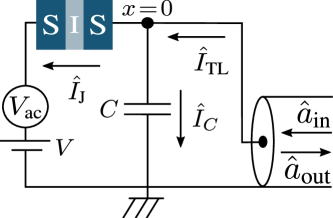
The proposed setup, illustrated in Fig. 1, operates as an amplifier in reflection mode. Parametric amplification is possible by taking advantage of the strong nonlinearity of the transport characteristics of the junction. To this end, we consider a dc-voltage bias smaller than twice the superconducting energy gap . At this bias point, the junction behaves as an open circuit and the conduction of quasiparticles is enabled by pumping it with a sinusoidal ac-voltage , where is the center measurement frequency. This voltage combination gives rise to modulations of the admittance of the junction , with the -th sideband of the pump, which generates ac-quasiparticle current at frequency . As we will show, the most important terms are: first, which is related to the coherent conversion process of one quanta of energy from the pump to two photons of frequencies , and second which is related to single-photon coherent (imaginary part) and dissipative (real part) response due to the tunneling of quasiparticles. By appropriately choosing the dc-voltage below twice the superconducting gap, we demonstrate that it is possible to make large enough while keeping Re close to zero in order to generate parametric amplification with near quantum-limited noise and squeezing. Furthermore, Im gives rise to a large frequency-dependent impedance mismatch which limits the gain and squeezing bandwidths. Fortunately, as we will present in Sec. III.3, this frequency-dependent impedance mismatch can be dealt with an impedance matching scheme.
It is surprising that even though SIS junctions are routinely used as high-frequency microwave quantum-limited mixers Zmuidzinas and Richards (2004); Westig et al. (2011), exploiting a very similar principle, their operation as parametric amplifiers have been mostly disregarded Lee (1982); Devyatov et al. (1986). Here, we use the input-output formalism Yurke and Denker (1984), together with photon-assisted tunneling theory Tien and Gordon (1963) to compute the parametric amplification and squeezing properties of an ac- and dc-voltage biased SIS junction Tucker and Feldman (1985). The resulting Heisenberg-Langevin equations Gardiner and Collett (1985) are numerically solved, allowing us to explore parametric amplification far from the small detuning limit considered previously Lee (1982); Devyatov et al. (1986). For an aluminum junction ( GHz) pumped at GHz and operated at temperatures , with the Boltzmann constant, we find that when operated in experimentally relevant conditions the device can produce more than 20 dB of phase-preserving and phase-sensitive gain, and dB of single- and two-mode squeezing. In the phase-preserving mode, the 3 dB gain bandwidth exceeds 1.2 GHz and, therefore, it is twice as large as the bandwidth of the broadband impedance engineered JPA Roy et al. (2015). Moreover, the 3 dB gain and squeezing bandwidths can be increased to 4.3 GHz with impedance matching schemes to compensate both the geometrical capacitance and dynamical susceptance Im of the junction Roy et al. (2015).
This article is organized as follows: In Sec. II we describe the input-output formalism used to characterize the device. Section III.1 presents results for an ideal SIS junction for which the transport response rises steeply at . The effects of the low-frequency noise, which captures most non-ideal effects, on the amplifier is described in Sec. III.2. An approach to improve further the performances of the amplifier relying on impedance engineering is presented in Sec. III.3. Final remarks are presented in Sec. IV.
II Model
We consider a SIS junction in parallel with its capacitance and connected to a transmission line (TL), see Fig. 1. The total Hamiltonian of the device is , with
| (1) |
describes the quasiparticles in the left () and right () superconductors forming the junction. In this expression, annihilates a quasiparticle of energy in the left (right) superconductor. The above Hamiltonian describes the dynamics of quasiparticles. However, Cooper pairs are also present and interact with the electromagnetic field. Since we are interested in signals of frequency amplified or squeezed by operating the junction close to the onset of quasi-particle transport , we neglect the effects from the tunneling of Cooper pairs whose Josephson frequency is . Experimentally, the effects of Cooper pairs can be further suppressed by passing one flux quantum within a SIS junction Tucker and Feldman (1985). This suppression can be done either fabricating the junction in a SQUID geometry or by applying an in-plane magnetic field to junction Westig et al. (2011).
The Hamiltonian of the electromagnetic environment, which includes the TL and the capacitor of the junction, is
| (2) |
The first and second terms account for the charging energy of the capacitor and the TL dynamics. The charge and flux operators obey ,. The TL characteristic impedance is defined in terms of its inductance and capacitance per unity of length. Finally, the last term of total Hamiltonian is the tunneling of quasiparticles dressed by the environment and it takes the form Devoret et al. (1990)
| (3) |
with the tunneling operator transferring a quasiparticle from the right to the left side of the junction with tunneling probability amplitude . The phase takes into account the ac-voltage and is the TL flux at the position of the junction .
In the interaction picture with respect to , this TL flux is written in terms of the incoming and outgoing fields as Yurke and Denker (1984)
| (4) |
with the wave number. The incoming (outgoing) field obeys the commutation relation .
To characterize the radiation emitted by the junction, we use the input-output formalism adapted to circuits coupled to quantum conductors Leppäkangas et al. (2015); Grimsmo et al. (2016); Mora et al. (2017). To obtain the input-output boundary condition, the first step is to derive the Heisenberg equations of motion for both TL charge and flux at the position of the junction (). The resulting equations are combined to express current conservation
| (5) |
which connects the outgoing field to the incoming field and the current of the junction . Using Eq. (II), the above equation can be expressed as an input-output relation
| (6) |
where is the Fourier transform of . The first term describes the phase shift due to the reflection of the input field by the capacitor. The last term characterizes the radiation emitted by the junction and it gives rise to both current fluctuations and a deterministic response to the applied voltages Grimsmo et al. (2016); Mora et al. (2017).
The current depends not only on the dc- and ac-voltages, but also on the TL voltage, , implying that and do not commute. To circumvent the non-commutation between and , we take advantage of the weak TL-junction coupling (for a typical TL impedance Zakka-Bajjani et al. (2010); Gasse et al. (2013), with k the quantum of resistance) and compute to second-order in the TL-junction coupling Mendes and Mora (2015); Grimsmo et al. (2016). In the time domain and for weak coupling to the environment, the current operator, in the Heisenberg picture, takes the form
| (7) |
where and are respectively the quasiparticle current and tunneling operators in the absence of TL voltage. The final step is to time-evolve . Using linear response theory, the quasiparticles operators are time evolved, in the interaction picture, with the interaction Hamiltonian , with superscript meaning the operator in interaction picture. Once more, we take advantage of the weak TL-junction coupling and the short interaction time between the quasiparticles and photons to expand the time-evolution operator to first-order in the to obtain
| (8) |
The first term is the current operator due to quasiparticle tunneling and it depends on the ac- and dc-voltage biases, while the two last terms describe modifications of the current fluctuations due to TL field. In the weak interaction limit considered here, we average over the quasiparticle operators in the terms proportional to , i.e.,
| (9) |
This approximation is equivalent to the Born-Markov approximation Mendes and Mora (2015); Grimsmo et al. (2016). Under these approximations, the current operator is written in frequency space as
| (10) |
with and the Fourier transforms 111Fourier transform of the operator is defined as , in accordance with quantum mechanics definition. of and , respectively. The generalized admittance
| (11) |
relates the current response at frequency to the TL-voltage dynamics at frequency Mora et al. (2017). The admittance is defined in terms of the photon-assisted current-current correlator where
| (12) |
is non-symmetrized photon-assisted current noise Mendes and Mora (2015); Grimsmo et al. (2016); Mora et al. (2017). It is defined in terms of the Bessel function and of the equilibrium current noise Ingold and Nazarov (1992).
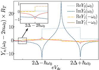
Equation (10) describes the linear response of the junction due to TL-voltage fluctuations. In the absence of ac-voltage, the linear response is strictly local in frequency with . On the other hand, the addition of the ac bias leads to due to TL-voltage fluctuations at frequencies of the pump sidebands . It is important to mention that is only non-zero for nonlinear junctions Mora et al. (2017). Consequently, in this device, parametric interaction is due to the combination of both photon-assisted transport and nonlinearity. For instance, the nonlinearity converts a single pump photon of frequency into two photons of frequency Clerk et al. (2010). In the SIS amplifier, this process is characterized by and allows for parametric amplification and squeezing Mendes and Mora (2015). As will be clear from Eq. (15), parametric amplification arises when . Fig. 2 illustrates the dc-voltage dependence of and for a weak pump amplitude . From the above criteria, parametric amplification and squeezing occurs for (see inset Fig. 2). At this dc voltage, single-photon dissipation Re is approximately zero, which is a necessary condition to reach near quantum-limited noise and large degree of squeezing by virtue of the fluctuation-dissipation theorem. Unsurprisingly, this dc voltage is also the optimal operational point of SIS mixers Tucker and Feldman (1985). In Fig. 2, the admittance present discontinuities for dc-voltages . These discontinuities are a characteristic of photon-assisted transport and nonlinearity. The real parts exhibit jumps which are replica of the SIS - curve while the imaginary parts exhibit logarithmic singularities. In practice, these discontinuities are rounded by experimental noise, finite Dynes parameter Pekola et al. (2010), finite temperature and, in our simulations, by numerical precision. Finally, it is important to emphasize that and depend only on the quasiparticles dynamics determined by , and on the intrinsic characteristics of the junction, e.g., the superconducting gap and normal state resistance .
As mentioned above, parametric interaction emerges from two-photon processes characterized by , while single-photon processes are characterized by . The other non-local frequency contributions, from the second term of Eq. (10), give rise to conversion processes where photons of frequency are up- or down-converted to . As theses contributions are detrimental to amplification and squeezing, we consider that an on-chip low-pass filter is used to filter all frequencies above . As a consequence, we can safely neglect all the contributions to current operator originating from in the sum over in Eq. (10), which takes the form
| (13) |
In addition to the low-pass filter, the time of the junction acts as a high-frequency cutoff. For the results presented in the next section, we take GHz as a fixed parameter of the junction, which is obtained for a normal state resistance and fF.
Within these approximations, the expression for the outgoing field in terms of the incoming field and of the quasiparticles current operators is obtained by replacing Eq. (13) into Eq. (6). After simple algebraic manipulation, the outgoing field is
| (14) |
with the frequency detuning and the reflection coefficient
| (15) |
where we defined , and . Here, terms proportional to and are the internal TL decay rates at which the junction absorbs and emits photons, respectively. The terms proportional to and Im are related to the geometrical capacitance and dynamical susceptance of the junction. In the second term of Eq. (II), we have introduced , with . As expected, the Fourier coefficient of is proportional to . Moreover, the coefficients of are , and , with .
Equation (II) is a central result of this paper and shows that the dc- and ac-voltage biased SIS junction acts as an amplifier operating in reflection mode. More specifically, for a fixed frequency detunig , the operators and commute and can be seen as the input signal and the idler mode operators of a phase-preserving amplifier Caves (1982); Clerk et al. (2010). In this mode, the gain is simply given by and the last two terms of Eq. (II) correspond to added noise beyond the quantum limit . To characterize the effects of quasiparticle tunneling on the performance of the amplifier, we compute the added noise using the relation Caves (1982); Boutin et al. (2017), with and the added noise
| (16) |
The terms proportional to and are noise generated by the tunneling of quasiparticles, and they originate from absorption and emission processes of one and two quantum of energy by the junction. As expected, the quasiparticle noise increases the added noise of the amplifier. Thus, to mitigate the effects of the quasiparticle noise, the operational voltages of the device are such that and are as small as possible. To characterize the deviation of the quantum limit, we define the quantum efficiency of parametric amplifier as . For an ideal phase-preserving amplifier and in the presence of quasiparticle noise .
For , and do not commute, and the first two terms of Eq. (II) rather characterize an ideal phase-sensitive amplifier Caves (1982); Clerk et al. (2010). In this operational mode, the gain is defined as a combination of , and the phases of the input and output fields Boutin et al. (2017). The added noise is given by a linear combination of the two last terms of Eq. (II) and it also depends on the input and output field phases Boutin et al. (2017).
To better characterize the radiation emitted by the SIS amplifier, we also compute bellow the output power spectrum , defined in terms of , with the output field quadrature with fluctuations and the phase of the output field. Similarly to amplification, the emitted radiation can be also characterized by single-mode or two-mode squeezed state.
III Results
We first present results for an ideal SIS junction, with transport response rising steeply for voltages as illustrated in Fig. 2(b). We then investigate how gain and squeezing properties are affected by low-frequency noise, which are smoothing out the transport response of the junction and, consequently, diminishing the strength of the parametric interaction. Lastly, an impedance matching scheme is presented. This scheme is used to match both the geometrical capacitance and dynamical susceptance [] of the junction, thus leading to much larger bandwidths.
III.1 Ideal SIS junction
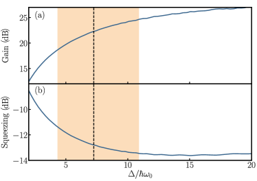
Before considering the general frequency-dependent amplification and squeezing, we present results for zero frequency detuning (). First, we investigate the effect of the strength of nonlinearities on the phase-sensitive mode. Figs. 3(a) and (b) illustrate, respectively, the phase-sensitive gain and single-mode squeezing as a function of , when optimizing to maximize single-mode squeezing for (see horizontal solid line in Fig. 4). This dc voltage is in the vicinity of the logarithmic singularity showed in the inset of Fig. 2; its choice is explained Fig. 4. In Fig. 3, varies while is kept fixed and equal to 6 GHz. Already at small we observe more than dB of amplification and dB of squeezing. As increases, the strength of the nonlinearities giving rise to parametric interaction increases, thus enhancing gain and squeezing as illustrated in Fig. 3. Thus, increasing leads to an increase of the parametric interaction strength . For , amplification and squeezing reach approximately dB and dB, respectively. Here, the filled area corresponds to in the 4 to 10 GHz range for an aluminum junction with GHz. A larger value of can be obtained by reducing the thickness of the aluminum layer Chubov et al. (1969) or with a different superconductor. The dashed line corresponds to GHz, the value used to investigate the frequency-dependent features of the SIS amplifier. The optimal ac-voltage decreases as increases (not shown).
For the remainder of this article, we consider an aluminum SIS junction with GHz (). To further gain insight on the parametric amplifier operational voltages, we investigate dc- and ac-voltage dependence of single-mode squeezing and phase-preserving gain at zero frequency detuning . Fig. 4 shows contours of constant gain (dashed lines) and squeezing (solid lines) in the vicinity of the logarithmic singularity .
We first investigate the phase-preserving gain. The different voltage points realizing a given gain do not result in the same device performances, which are characterized by quantum efficiency and 3 dB bandwidth. The former improves when the quasiparticle noise terms in Eq. (II) are reduced. By virtue of the fluctuation-dissipation theorem, noise is related to the dissipation . Fig. 4 shows that, in the voltage range of interest, is nearly independent of dc-voltage and increases with increasing ac voltage. Accordingly, along a contour of constant gain, going to lower ac voltage increases the quantum efficiency. Remarkably, we find numerically that it also increases the 3 dB bandwidth. In principle, in the limit , one would get perfect quantum efficiency, . However, for a given gain, decreasing the ac voltage requires to set the dc voltage increasingly closer to the logarithmic singularity. At some point, the logarithmic singularity is smoothed out by experimental noise on the dc voltage or non-ideal - curve (finite Dynes parameter). This will set the best experimental performances of the device. For the remainder of the paper, the dc voltage is set to the experimentally relevant value and, consequently, gain and squeezing are tuned in-situ by varying the ac-voltage (horizontal line in Fig. 4).
We now turn to squeezing. Similarly to quantum efficiency, squeezing is strongly sensitive to the quasiparticle noise terms, which are related to . For a given , is almost constant. As a consequence, we expect squeezing to be maximum for the giving infinite gain (thick solid curve in Fig. 4, where the denominator of the gain, , tends to zero, i.e, .). At infinite gain, an ideal amplifier would also produce infinite squeezing; however, the finite quasiparticle noise (Re) bounds squeezing. Analogously to quantum efficiency, maximum squeezing will thus continuously improve by lowering the ac voltage at the expense of setting the dc voltage closer to the logarithmic discontinuity. Also infinite squeezing could be achieved in the limit , the maximum experimentally achievable value will be bounded by the smoothing of the logarithmic singularity. Squeezing reaching -15 dB could be achieved with the current experimental setups.
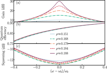
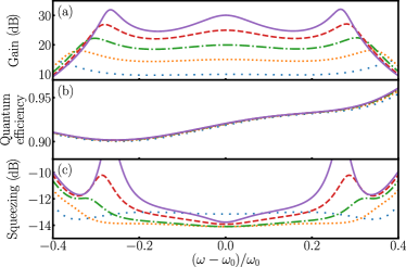
Figure 5 shows (a) phase-preserving gain, (b) quantum efficiency and (c) squeezing as a function of frequency detuning for and several ac-voltage amplitudes: (dotted line), (dashed-dotted line), (long-dashed line), (dashed line), (solid line). The gain, Fig. 5(a), is observed to increase with increasing ac-voltage amplitude while its 3 dB bandwidth decreases. In the 20 to 30 dB range, the gain-bandwidth product is approximately constant, equal to 12 GHz. This value is 87% larger than the gain-bandwidth product of the broadband impedance engineered JPA Roy et al. (2015). Fig. 5(b) shows that the quantum efficiency is close to 0.9 in the 3 dB bandwidth frequency range and nearly independent of ac-voltage amplitude. This is expected from the small but finite observed in Fig. 4. Fig. 5(c) illustrates a far-separated two-mode squeezing with 3 dB bandwidth reaching GHz. Moreover, unlike gain, squeezing varies only weakly with the ac-voltage amplitude and, after it reaches its maximum value, further increase of the ac-voltage amplitude reduces squeezing, as expected from Fig. 4.
III.2 Effects of low-frequency noise
The results presented in the previous section were obtained considering an ideal SIS junction in the low-temperature limit for which the transport response is singular and discontinuous for Barone and Paterno (1982). However, this is an idealized situation and, in practice, temperature or low-frequency noise can smoothen the transport response. Here, we consider the effects of low-frequency noise on gain and squeezing properties of the SIS amplifier. These effects are included by assuming that the junction interacts with a low-frequency electromagnetic environment Hofheinz et al. (2011) and that the transport properties are described by the -theory Ingold and Nazarov (1992). This approach has been shown to quantitatively explain the finite Dynes tunneling density of states Pekola et al. (2010), usually observed below the dc-transport gap in a normal-insulator-superconductor junctions and the corresponding smoothing of the BCS coherence peak Barone and Paterno (1982). In this approach, the low-frequency noise modifies the equilibrium noise current noise to
| (17) |
where is the probability density of a tunneling quasiparticle emitting energy Ingold and Nazarov (1992).
To model the low-frequency electromagnetic environment, we consider that it originates from the dc-bias scheme. In general, the biasing scheme consists of a resistive voltage divider followed by large capacitive filtering Hofheinz et al. (2011); Chen et al. (2014). In this situation, the low-frequency impedance is thus the parallel combination of a resistance with a large capacitance . This filtering scheme reduces the bandwidth over which low-frequency voltage noise is detrimental to the kHz range Chen et al. (2014), making the low-frequency voltage fluctuations fully classical. In this setup, the effect low-frequency environment on the transport properties is then described by
| (18) |
with is the capacitor charging energy. With this model, the theory developed in Sec. II remains the same except for the replacement of by in Eq. (II).
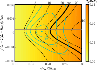
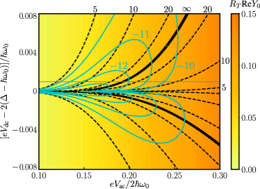
Figure 6 illustrates the effect of low-frequency environment on gain (dashed lines), squeezing (solid lines) and the single-photon dissipation Re (heat map) as a function of the dc- and ac-voltages. The filtering scheme is characterized by nF corresponding to rms voltage fluctuations of nV. As expected, the low-frequency noise removes the logarithmic singularity at (see Fig. 4). Similarly to the ideal case, single-photon dissipation Re is nearly independent of the dc voltage and increases with increasing ac voltage. Maximization of the device performances will thus again require to lower the ac voltage. However, along a contour of constant gain (dashed lines) or squeezing (solid lines), now has a finite lower bound. Unlike Fig. 4 where the device performances constantly increased toward and infinite squeezing by setting the dc voltage closer and closer to the logarithmic singularity , here we expect approximately constant performances when . The presence of low-frequency noise bounds the squeezing to a maximum value of approximately dB (round-blue dot). The maximum squeezing depends strongly on the filtering capacitor and it decreases for smaller capacitances. In contrast, note that gain remains tuneable to any value up to infinity by the dc- and ac-voltages at the expense of increasing single-photon dissipation Re.
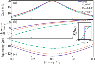
We now investigate the effects of the low-frequency noise on the frequency-dependent properties of the amplifier. Fig. 7 illustrates (a) gain, (b) quantum efficiency and (c) squeezing for and three different filtering capacitances: nF (dotted line), nF (dashed line) and pF (dashed-dotted line), respectively. The ac voltage is set to give 20 dB of gain at zero detuning. These results are compared with the ideal case (solid line), where the junction does not interact with the low-frequency environment. For an aluminum junction () and mK, nF corresponds to rms voltage fluctuations of nV (dot-dashed line), the gain, added noise and squeezing are only weakly affected by the low-frequency environment which is efficiently filtered. The effect of low-frequency noise on is illustrated in the inset of Fig. 7. For nF, is almost indistinguishable from the ideal case (dashed line), a signature that the low-frequency noise is efficiently filtered. On the other hand, under less efficient filtering, pF corresponding to V rms voltage fluctuations (dashed line) and nF, the equilibrium current noise rises smoothly and its behavior near deviates from the ideal case (see inset). In these cases, low-frequency noise diminishes both quantum efficiency and squeezing [dashed and dashed-dotted lines in (b) and (c)]. However, the 3 dB bandwidth is weakly diminished. Furthermore, the main effect of the low-frequency noise is to diminish the strength of the nonlinearity giving rise to parametric interaction and, therefore, to obtain higher gains the ac-voltage amplitude must be increased. The increasing of the ac voltage enhances single-photon dissipation Re and degrades quantum efficiency and squeezing.
III.3 Impedance matching
At first sight, the aforementioned gain-bandwidth product of 12 GHz is quite surprising since the energy scale of the SIS parametric amplifier is the superconducting gap voltage (), which corresponds to frequencies of approximately 90 GHz for aluminum junctions. To understand what is limiting the gain-bandwidth product, we recall that the phase-preserving gain is determined by the reflection coefficient [Eq. (15)], and its frequency dependence is due to and . Fig. 8(a) illustrates the frequency dependence of and for and . The parametric conversion term is real, independently of the voltages, and is fairly flat in a wide band of frequencies. Also, as expected, the dissipation is negligible for all frequencies. The contribution of the geometrical capacitance depends weakly on frequency. Consequently, the strong frequency dependence of gain originates from the dynamical susceptance .
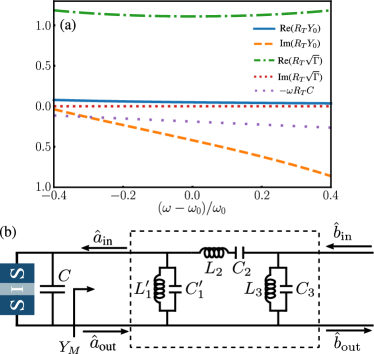
In order to develop a matching scheme to increase the gain-bandwidth product, we first note that the frequency dependence of Im is modeled with reasonable accuracy by a parallel tank with the following characteristics: and . Note that the precise values of and depend on and . However, the above approximate values of and are sufficient to match Im for a wide range of voltages. Following Ref. Matthaei et al., 1964, the matching scheme consists in adding, between the SIS junction and the TL, a bandpass filter network (black box). In the bandpass filter network, depicted in Fig. 8(b), the first capacitance (inductance) () has been reduced (increased) compared to the original filter capacitance (inductance ) to (). In this manner, the effect of and is absorbed in the filter. Since the filter is designed to achieve good matching in the passband, the detrimental effects of and are eliminated.
To obtain an experimentally useful parametric amplifier, we choose filter elements and giving a 3-poles Chebyshev filter with 4-8 GHz band edges. Such filters are also characterized by their ripples. While the Chebyshev filter benefically leads to an increase in the gain-bandwidht product, its ripples on the other hand impact directly the gain flatness. The ripples amplitude is directly related to the capacitance of the filter network. To reduce the amplitude of the ripples, the capacitance must be made as small as possible Matthaei et al. (1964) with the constraint . In this way, we choose to minimize the amplitude of the ripples.
Once the elements of the filter are determined, we can readily incorporate it in the quantum formalism via the -matrix formalism, which gives the sets of linear equations
| (19) |
and
| (20) |
to be solved together with Eq. (II). Here, is the -matrix that connects the SIS junction fields to the TL fields [see Fig. 8(b)]. With this formalism, the definitions of the gain, quantum efficiency and squeezing remain the same provided that is replaced by . In the presence of the filter, the phase-preserving gain takes the form Matthaei (1961)
| (21) |
where and is the filter-matching-network admittance [see Fig. 8(a)].
Figure 9 shows the (a) phase-preserving gain, (b) quantum efficiency and (c) squeezing for various values of at . As shown in Fig. 9(a), the matching scheme dramatically increases the 3 dB bandwidth of the phase-preserving gain to 4.3 GHz, for a gain of dB, from the GHz bandwidth obtained without the matching circuit [see Fig. 5(a)]. The gain ripples are induced by the Chebyshev ripples of the filter reflection coefficient; the higher the gain the higher the amplitude of the ripples. The two extra peaks at the band edges are due to the diminution of at the band edges, which at some frequency cancel the real part of the denominator of Eq. (21). Reduction of the band edge peaks can be done by adding an imaginary part to the denominator of Eq. (21) at the band edges Matthaei (1961). Here, this is achieved by slightly overestimating the first inductance .
The compensation of the frequency dependence of has not only increased the 3 dB bandwidth, but also enhanced quantum efficiency [Fig. 9(b)] and maximum squeezing [Fig. 9(c)]. The improvement of the quantum efficiency and squeezing is due to the reduction of ac-voltage amplitude and, consequently, single-photon dissipation . For instance, a gain of 20 dB is now achieved with an ac-amplitude of (dashed-dotted line), a reduction of 13% in comparison to the amplifier without the matching circuit [Fig. 5(a)]. Squeezing now has complex shape at higher gains but remains extremely flat for dB.
It is remarkable to obtain such an improvement in a wide bandwidth by using a simple 3-poles filter, designed to match purely capacitive or inductive elements of passive circuits. Indeed, the SIS parametric amplifier is an active circuit with a non-linear dynamical susceptance . Such filters can be fabricated directly on-chip either by realizing lumped capacitors and inductors, or using distributed elements such as lines.
III.4 Dynamical range
An important characteristic of any parametric amplifier is its dynamical range, which determines how many photons can be amplified without saturating the device. In general, the dynamical range is limited by higher order non-linearities of the Hamiltonian and depletion of the pump Roy and Devoret (2018). Thus, similarly to SIS mixers, we expect that the dynamical range for a single-junction amplifier to be small. However, we can ensure that amplification of vacuum fluctuations will not saturate the SIS amplifier. This requires the power of amplified vacuum fluctuations, , to be lower than the power delivered by the pump, . However, for amplification in a wide bandwidth, as shown in Fig. 9, we obtain a ratio . This can be overcome by use of a standard approach to design SIS mixers: using identical SIS junctions in series. It is shown in Ref. Tucker and Feldman, 1985 that such an array is equivalent to a single junction with a pump and saturation power times larger. The underlying mechanism is easily understood: the impedance of a series array of SIS junctions is simply times the impedance of a single junction. Thus, adding junctions of resistance in series, the admittance remains the same. However, as the photon-assisted effects, necessary for parametric amplification and squeezing, are proportional to , with the applied pump voltage to each junction, the total pump voltage across the array has to be times large. As a consequence, we expect an array of only 5 to 10 SIS junctions to give an experimental relevant dynamical range.
One alternative to increase the dynamical range of a single-junction amplifier is to use a very low-impedance junction (), together with an impedance transformer to match the low-impedance junction with the transmission line. Indeed, decreasing the junction impedance increases the pump power by the same amount. In practice, a broadband impedance transformation can be implemented either by an extra network of quarter wavelength transmission lines or directly into the filter matching network by using shunt resonators and admittance inverters in between Matthaei et al. (1964).
IV Final remarks
We have proposed a near-quantum-limited broadband amplifier and squeezer based on the photon-assisted tunneling of quasiparticles in a SIS junction. This device can function as a phase-sensitive or phase-preserving amplifier. The gain can be tuned by ac-voltages amplitude to reach gain-bandwidth products of approximatally 12 GHz in the 20-30 dB range, which is 87% larger than the impedance-engineered Josephson parametric amplifier Roy et al. (2015). This device is also a source of far separated two-mode squeezing with 3 dB bandwidth of approximately 5 GHz and dB of squeezing at the center frequency. Moreover, gain and two-mode squeezing can be fine-tuned in-situ by simply changing the pumping tone amplitude and frequency. For few GHz bandwidth applications, a matching impedance circuit was developed. The proposed matching scheme allows for 3 dB bandwidth of 4 GHz. Also, we estimate that dynamical range of the such a broadband amplifier can be enhanced by replacing the single junction by an array of 5 to 10 SIS junctions. To conclude, the design and fabrication simplicity of this SIS amplifier, together with its operational-mode flexibility, makes it a versatile near-quantum-limited microwave amplifier and squeezer, that can be easily integrated in many quantum microwave experiments.
Acknowledgments
U.C.M thanks S. Boutin, A. L. Grimsmo, and M. Westig for fruitful discussions, and the Quantronics group for hospitality. U.C.M., S.J., B.R. and A.B. were supported by the Canada First Research Excellence Fund and NSERC. S.J. and B.R. were supported by Canada Excellence Research Chairs, the Government of Canada, Québec MEIE, Québec FRQNT via INTRIQ, Université de Sherbrooke via EPIQ, and the Canada Foundation for Innovation. The research at CEA Saclay received funding from the European Research Council under the European Union’s Horizon 2020 program (European Research Council Grant Agreement No. 639039) and support from the ANR AnPhoTeQ research contract.
References
- Wallraff et al. (2004) A. Wallraff, D. I. Schuster, A. Blais, L. Frunzio, R.-S. Huang, J. Majer, S. Kumar, S. M. Girvin, and R. J. Schoelkopf, “Strong coupling of a single photon to a superconducting qubit using circuit quantum electrodynamics,” Nature 431, 162 (2004).
- Castellanos-Beltran and Lehnert (2007) M. A. Castellanos-Beltran and K. W. Lehnert, “Widely tunable parametric amplifier based on a superconducting quantum interference device array resonator,” Appl. Phys. Lett. 91, 083509 (2007).
- Bergeal et al. (2010) N. Bergeal, F. Schackert, M. Metcalfe, R. Vijay, V. E. Manucharyan, L. Frunzio, D. E. Prober, R. J. Schoelkopf, S. M. Girvin, and M. H. Devoret, “Phase-preserving amplification near the quantum limit with a josephson ring modulator,” Nature 465, 64 (2010).
- Zhou et al. (2014) X. Zhou, V. Schmitt, P. Bertet, D. Vion, W. Wustmann, V. Shumeiko, and D. Esteve, “High-gain weakly nonlinear flux-modulated josephson parametric amplifier using a squid array,” Phys. Rev. B 89, 214517 (2014).
- Eichler et al. (2014) C. Eichler, Y. Salathe, J. Mlynek, S. Schmidt, and A. Wallraff, “Quantum-limited amplification and entanglement in coupled nonlinear resonators,” Phys. Rev. Lett. 113, 110502 (2014).
- Jebari et al. (2018) S. Jebari, F. Blanchet, A. Grimm, D. Hazra, R. Albert, P. Joyez, D. Vion, D. Esteve, F. Portier, and M. Hofheinz, “Near-quantum-limited amplification from inelastic cooper-pair tunnelling,” Nature Electronics 1, 223 (2018).
- Walter et al. (2017) T. Walter, P. Kurpiers, S. Gasparinetti, P. Magnard, A. Potocnik, Y. Salathé, M. Pechal, M. Mondal, M. Oppliger, C. Eichler, and A. Wallraff, “Rapid high-fidelity single-shot dispersive readout of superconducting qubits,” Phys. Rev. Applied 7, 054020 (2017).
- Vijay et al. (2011) R. Vijay, D. H. Slichter, and I. Siddiqi, “Observation of quantum jumps in a superconducting artificial atom,” Phys. Rev. Lett. 106, 110502 (2011).
- Zakka-Bajjani et al. (2010) Eva Zakka-Bajjani, J. Dufouleur, N. Coulombel, P. Roche, D. C. Glattli, and F. Portier, “Experimental determination of the statistics of photons emitted by a tunnel junction,” Phys. Rev. Lett. 104, 206802 (2010).
- Gasse et al. (2013) G. Gasse, C. Lupien, and B. Reulet, “Observation of squeezing in the electron quantum shot noise of a tunnel junction,” Phys. Rev. Lett. 111, 136601 (2013).
- Stehlik et al. (2015) J. Stehlik, Y.-Y. Liu, C. M. Quintana, C. Eichler, T. R. Hartke, and J. R. Petta, “Fast charge sensing of a cavity-coupled double quantum dot using a josephson parametric amplifier,” Phys. Rev. Applied 4, 014018 (2015).
- Westig et al. (2017) M. Westig, B. Kubala, O. Parlavecchio, Y. Mukharsky, C. Altimiras, P. Joyez, D. Vion, P. Roche, D. Esteve, M. Hofheinz, M. Trif, P. Simon, J. Ankerhold, and F. Portier, “Emission of nonclassical radiation by inelastic cooper pair tunneling,” Phys. Rev. Lett. 119, 137001 (2017).
- Simoneau et al. (2017) J. O. Simoneau, S. Virally, C. Lupien, and B. Reulet, “Photon-pair shot noise in electron shot noise,” Phys. Rev. B 95, 060301 (2017).
- Bienfait et al. (2017) A. Bienfait, P. Campagne-Ibarcq, A. H. Kiilerich, X. Zhou, S. Probst, J. J. Pla, T. Schenkel, D. Vion, D. Esteve, J. J. L. Morton, K. Moelmer, and P. Bertet, “Magnetic resonance with squeezed microwaves,” Phys. Rev. X 7, 041011 (2017).
- Brubaker et al. (2017) B. M. Brubaker, L. Zhong, Y. V. Gurevich, S. B. Cahn, S. K. Lamoreaux, M. Simanovskaia, J. R. Root, S. M. Lewis, S. Al Kenany, K. M. Backes, I. Urdinaran, N. M. Rapidis, T. M. Shokair, K. A. van Bibber, D. A. Palken, M. Malnou, W. F. Kindel, M. A. Anil, K. W. Lehnert, and G. Carosi, “First results from a microwave cavity axion search at ,” Phys. Rev. Lett. 118, 061302 (2017).
- Castellanos-Beltran et al. (2008) M. A. Castellanos-Beltran, K. D. Irwin, G. C. Hilton, L. R. Vale, and K. W. Lehnert, “Amplification and squeezing of quantum noise with a tunable josephson metamaterial,” Nat. Physics 4, 929 (2008).
- Murch et al. (2013) K. W. Murch, S. J. Weber, K. M. Beck, E. Ginossar, and I. Siddiqi, “Reduction of the radiative decay of atomic coherence in squeezed vacuum,” Nature 499, 62 (2013).
- Toyli et al. (2016) D. M. Toyli, A. W. Eddins, S. Boutin, S. Puri, D. Hover, V. Bolkhovsky, W. D. Oliver, A. Blais, and I. Siddiqi, “Resonance fluorescence from an artificial atom in squeezed vacuum,” Phys. Rev. X 6, 031004 (2016).
- Didier et al. (2015) N. Didier, A. Kamal, W. D. Oliver, A. Blais, and A. A. Clerk, “Heisenberg-limited qubit read-out with two-mode squeezed light,” Phys. Rev. Lett. 115, 093604 (2015).
- Puri and Blais (2016) S. Puri and A. Blais, “High-fidelity resonator-induced phase gate with single-mode squeezing,” Phys. Rev. Lett. 116, 180501 (2016).
- Royer et al. (2017) B. Royer, A. L. Grimsmo, N. Didier, and A. Blais, “Fast and high-fidelity entangling gate through parametrically modulated longitudinal coupling,” Quantum 1, 11 (2017).
- Braunstein and van Loock (2005) S. L. Braunstein and P. van Loock, “Quantum information with continuous variables,” Rev. Mod. Phys. 77, 513–577 (2005).
- Grimsmo and Blais (2017) A. L. Grimsmo and A. Blais, “Squeezing and quantum state engineering with josephson travelling wave amplifiers,” npj Quantum Information 3, 20 (2017).
- Boutin et al. (2017) S. Boutin, D. M. Toyli, A. V. Venkatramani, A. W. Eddins, I. Siddiqi, and A. Blais, “Effect of higher-order nonlinearities on amplification and squeezing in josephson parametric amplifiers,” Physics Review Applied 8, 054030 (2017).
- Westig and Klapwijk (2018) M. P. Westig and T. M. Klapwijk, “Josephson parametric reflection amplifier with integrated directionality,” Phys. Rev. Appl 9, 064010 (2018).
- Mutus et al. (2014) J. Y. Mutus, T. C. White, R. Barends, Y. Chen, Z. Chen, B. Chiaro, A. Dunsworth, E. Jeffrey, J. Kelly, A. Megrant, C. Neill, P. J. J. O’Malley, P. Roushan, D. Sank, A. Vainsencher, J. Wenner, K. M. Sundqvist, A. N. Cleland, and J. M. Martinis, “Strong environmental coupling in a josephson parametric amplifier,” Appl. Phys. Lett. 104, 263513 (2014).
- Roy et al. (2015) T. Roy, S. Kundu, M. Chand, A. M. Vadiraj, A. Ranadive, N. Nehra, M. P. Patankar, J. Aumentado, A. A. Clerk, and R. Vijay, “Broadband parametric amplification with impedance engineering: Beyond the gain-bandwidth product,” Appl. Phys. Lett. 107, 262601 (2015).
- Macklin et al. (2015) C. Macklin, K. O’Brien, D. Hover, M. E. Schwartz, V. Bolkhovsky, X. Zhang, W. D. Oliver, and I. Siddiqi, “A near–quantum-limited josephson traveling-wave parametric amplifier,” Science 350, 307 (2015).
- Beenakker and Schomerus (2004) C. W. J. Beenakker and H. Schomerus, “Antibunched photons emitted by a quantum point contact out of equilibrium,” Phys. Rev. Lett. 93, 096801 (2004).
- Armour et al. (2013) A. D. Armour, M. P. Blencowe, E. Brahimi, and A. J. Rimberg, “Universal quantum fluctuations of a cavity mode driven by a josephson junction,” Phys. Rev. Lett. 111, 247001 (2013).
- Leppäkangas et al. (2015) Juha Leppäkangas, Mikael Fogelström, Alexander Grimm, Max Hofheinz, Michael Marthaler, and Göran Johansson, “Antibunched photons from inelastic cooper-pair tunneling,” Phys. Rev. Lett. 115, 027004 (2015).
- Mendes and Mora (2015) U. C. Mendes and C. Mora, “Cavity squeezing by a quantum conductor,” New J. Phys. 17, 113014 (2015).
- Mendes and Mora (2016) U. C. Mendes and C. Mora, “Electron-photon interaction in a quantum point contact coupled to a microwave resonator,” Phys. Rev. B 93, 235450 (2016).
- Zmuidzinas and Richards (2004) J. Zmuidzinas and P. L. Richards, “Superconducting detectors and mixers for millimeter and submillimeter astrophysics,” Proc. IEEE 92, 1597 (2004).
- Westig et al. (2011) M P Westig, K Jacobs, J Stutzki, M Schultz, M Justen, and C E Honingh, “Balanced superconductor-insulator-superconductor mixer on a 9 µm silicon membrane,” Superconductor Science and Technology 24, 085012 (2011).
- Lee (1982) G. S. Lee, “Superconductor-insulator-superconductor reflection parametric amplifier,” Appl. Phys. Lett. 41 (1982), 10.1063/1.93468.
- Devyatov et al. (1986) I. A. Devyatov, L. S. Kuzmin, K. K. Likharev, V. V. Migulin, and A. B. Zorin, “Quantum-statistical theory of microwave detection using superconducting tunnel junctions,” Journal of Applied Physics 60, 1808 (1986).
- Yurke and Denker (1984) Bernard Yurke and John S. Denker, “Quantum network theory,” Phys. Rev. A 29, 1419–1437 (1984).
- Tien and Gordon (1963) P. K. Tien and J. P. Gordon, “Multiphoton process observed in the interaction of microwave fields with the tunneling between superconductor films,” Phys. Rev. 129, 647–651 (1963).
- Tucker and Feldman (1985) J. R. Tucker and M. J. Feldman, “Quantum detection at millimeter wavelengths,” Rev. Mod. Phys. 57, 1055 (1985).
- Gardiner and Collett (1985) C. W. Gardiner and M. J. Collett, “Input and output in damped quantum systems: Quantum stochastic differential equations and the master equation,” Phys. Rev. A 31, 3761–3774 (1985).
- Devoret et al. (1990) M. H. Devoret, D. Esteve, H. Grabert, G.-L. Ingold, H. Pothier, and C. Urbina, “Effect of the electromagnetic environment on the coulomb blockade in ultrasmall tunnel junctions,” Phys. Rev. Lett. 64, 1824–1827 (1990).
- Grimsmo et al. (2016) A. L. Grimsmo, F. Qassemi, B. Reulet, and A. Blais, “Quantum optics theory of electronic noise in coherent conductors,” Phys. Rev. Lett. 116, 043602 (2016).
- Mora et al. (2017) C. Mora, C. Altimiras, P. Joyez, and F. Portier, “Quantum properties of the radiation emitted by a conductor in the coulomb blockade regime,” Phys. Rev. B 95, 125311 (2017).
- Note (1) Fourier transform of the operator is defined as , in accordance with quantum mechanics definition.
- Ingold and Nazarov (1992) G.-L. Ingold and Yu. V. Nazarov, Single Charge Tunneling, edited by H. Grabert and M.H. Devoret (Plenum Press, New York, 1992).
- Clerk et al. (2010) A. A. Clerk, M. H. Devoret, S. M. Girvin, F. Marquardt, and R. J. Schoelkopf, “Introduction to quantum noise, measurement, and amplification,” Rev. Mod. Phys. 82, 1155 (2010).
- Pekola et al. (2010) J. P. Pekola, V. F. Maisi, S. Kafanov, N. Chekurov, A. Kemppinen, Yu. A. Pashkin, O.-P. Saira, M. Möttönen, and J. S. Tsai, “Environment-assisted tunneling as an origin of the dynes density of states,” Phys. Rev. Lett. 105, 026803 (2010).
- Caves (1982) C. M. Caves, “Quantum limit on noise in linear amplifiers,” Phys. Rev. D 26, 1817 (1982).
- Chubov et al. (1969) P. N. Chubov, V. V. Eremenko, and Yu. A. Pilipenko, “Dependence of the critical temperature and energy gap on the thickness of superconducting aluminum films,” Soviet Physics JETP 28, 389 (1969).
- Barone and Paterno (1982) A. Barone and G. Paterno, Physcs and applications of the Josephson effect (A Wiley-Interscience publication, 1982).
- Hofheinz et al. (2011) M. Hofheinz, F. Portier, Q. Baudouin, P. Joyez, D. Vion, P. Bertet, P. Roche, and D. Esteve, “Bright side of the coulomb blockade,” Phys. Rev. Lett. 106, 217005 (2011).
- Chen et al. (2014) F. Chen, J. Li, A. D. Armour, E. Brahimi, J. Stettenheim, A. J. Sirois, R. W. Simmonds, M. P. Blencowe, and A. J. Rimberg, “Realization of a single-cooper-pair josephson laser,” Phys. Rev. B 90, 020506 (2014).
- Matthaei et al. (1964) G. L. Matthaei, L. Young, and E. M. T. Jones, Microwave Filters, Impedance-Matching Networks, and Coupling Structures (McGraw-Hill Book Company, 1964).
- Matthaei (1961) G. L. Matthaei, “A study of the optimum design of wide-band parametric amplifiers and up-converters,” IRE Transactions on Microwave Theory and Techniques 9, 23–38 (1961).
- Roy and Devoret (2018) Ananda Roy and Michel Devoret, “Quantum-limited parametric amplification with josephson circuits in the regime of pump depletion,” Phys. Rev. B 98, 045405 (2018).