Integration of Carrier Aggregation and Dual Connectivity
for the ns-3 mmWave Module
Abstract.
Thanks to the wide availability of bandwidth, the millimeter wave (mmWave) frequencies will provide very high data rates to mobile users in next generation 5G cellular networks. However, mmWave links suffer from high isotropic pathloss and blockage from common materials, and are subject to an intermittent channel quality. Therefore, protocols and solutions at different layers in the cellular network and the TCP/IP protocol stack have been proposed and studied. A valuable tool for the end-to-end performance analysis of mmWave cellular networks is the ns-3 mmWave module, which already models in detail the channel, Physical (PHY) and Medium Access Control (MAC) layers, and extends the Long Term Evolution (LTE) stack for the higher layers. In this paper we present an implementation for the ns-3 mmWave module of multi connectivity techniques for 3GPP New Radio (NR) at mmWave frequencies, namely Carrier Aggregation (CA) and Dual Connectivity (DC), and discuss how they can be integrated to increase the functionalities offered by the ns-3 mmWave module.
| Multi connectivity technique | Relevant specifications for NR at mmWave frequencies | Single or multi-RAT | Main features |
|---|---|---|---|
| Coordinated Multi-Point | Coordinated Multi-Point (CoMP) is not included in 3GPP NR specifications. Studied in (Maamari et al., 2016; MacCartney Jr et al., 2017; Tesema et al., 2017). | Single | Increases the received Signal to Noise Ratio (SNR) by combining multiple identical transmission |
|
Carrier Aggregation
(available in ns-3 mmWave) |
3GPP TS 38.300 (3GPP, 2018c), TR 38.802 (3GPP, 2017b). | Single | Increases the data rate or the diversity using multiple carriers with a common MAC layer |
|
Dual Connectivity
(available in ns-3 mmWave) |
3GPP TS 38.300 (3GPP, 2018c), TS 37.340 (3GPP, 2018b) | Both | Uses different cells to increase the data rate or the reliability, and improve the mobility management. Used for LTE-NR internetworking |
|
Multipath TCP
(available in ns-3 with Direct Code Execution (DCE) (Polese et al., 2017c; Tazaki et al., 2013)) |
RFC 6824 (Ford et al., 2013) (independent from 3GPP NR specifications) | Multi | Combines multiple TCP subflows on different network interfaces to increase the throughput |
|
Application layer solutions
(available in ns-3 with custom implementations (Drago et al., 2018)) |
Independent from specification bodies. Studied in (Drago et al., 2018) | Multi | Use different RATs to increase the diversity and improve the Quality of Experience |
1. Introduction
Communication at mmWave frequencies will be one of the key features of the fifth generation of cellular networks (5G), given that the wide available bandwitdh at these frequencies (Rappaport et al., 2013) can potentially enable multi-gigabit-per-second data rates (Boccardi et al., 2014; Pi and Khan, 2011) and satisfy the Enhanced Mobility Broadband 5G use case (Shafi et al., 2017). 3GPP New Radio (NR), the 5G standard for cellular networks, will support the communication at frequencies up to 52.6 GHz (3GPP, 2017b), and the first trials have confirmed the potential for ultra-high achievable throughput (Shafi et al., 2017).
However, there are several challenges to be addressed for a successful deployment of mobile mmWave networks, mainly related to the harsh propagation environment at such high frequencies, and in the recent years there have been several efforts focused on solving these issues. The first is the high isotropic propagation loss, which increases with the square of the carrier frequency. This is addressed by using highly directional communications, that increase the link budget and hence the range at which the communication is still feasible, and are enabled by the fact that with a small mmWave wavelength it is possible to pack many antenna elements in small areas (Roh et al., 2014; Sun et al., 2014). The second challenge is related to blockage, which prevents direct Line of Sight (LOS) communication in the presence of obstacles, buildings and even the human body (Rangan et al., 2014). Nonetheless, as shown in (Rappaport et al., 2013), in an urban environment with a rich scattering environment, it is possible to communicate also in Non Line of Sight (NLOS) using reflections, but with an Signal to Noise Ratio (SNR) with is approximatively 30 dB smaller. This problem can be solved with network densification, i.e., the increment in the density of the deployment of mmWave base stations, with inter-site distance in the order of a few hundreds of meters to decrease the outage probability (Rangan et al., 2014; Pi and Khan, 2011).
The characteristics of the communications at mmWave frequencies, however, also introduce challenges in the whole network stack. For example, the usage of directional transmissions requires new protocols for initial access and tracking at the Medium Access Control (MAC) layer (Shokri-Ghadikolaei et al., 2015), while the network densification and the sensitivity to blockage events call for fast network procedures to timely update the serving base station (Polese et al., 2017a). The performance of transport protocols is also affected by the intermittency of the mmWave channel, which causes the emergence of bufferbloat and low utilization of the available resources (Polese et al., 2017b).
The need for the design of cross-layer solution and the analysis of the performance of mmWave cellular networks in an end-to-end environment has motivated the introduction of a mmWave module for ns-3 (Ford et al., 2016), which is publicly available and extensively described in (Mezzavilla et al., 2017). It features the implementation of mmWave channel models (including the 3GPP model (Zhang et al., 2017)), and custom Physical (PHY) and MAC layers with a dynamic frame structure that adapts to the large bandwidth available at mmWaves (Dutta et al., 2017), and extends the higher layers of the Long Term Evolution (LTE) module implementation (e.g., by using queueing techniques in the Radio Link Control (RLC) buffers, or by modeling also the connection to the control elements of the core network). The module has been already used to study the performance of frame structures, schedulers, mobility management techniques and transport protocols in end-to-end mmWave cellular networks (Mezzavilla et al., 2017).
In this paper, we describe the implementation of two multi connectivity techniques that are included in the latest 3GPP specifications for NR (3GPP, 2018c) and the internetworking between LTE and NR (3GPP, 2018b) which can be used to improve the connection reliability and/or the throughput. In particular, we will focus on Carrier Aggregation (CA) for mmWave frequencies, and describe how it can be integrated with multi-Radio Access Technology (RAT) Dual Connectivity (DC) in a combined LTE-mmWave scenario. The inclusion of these features increases the realism and the capabilities of the ns-3 mmWave module, and enables the simulation of more complex scenarios with advanced multi-RAT solutions, agile spectrum management and higher throughput.
The remainder of the paper is organized as follows. In Sec. 2 we describe the main multi connectivity solutions for mmWave cellular networks, with a focus on CA and DC and the related 3GPP specifications. In Sec. 4 we present the implementation of CA, and in Sec. 3 we discuss that of the DC and the integration between the two. In Sec. 5 we report some examples and results, and we conclude the paper and provide insights on future works in Sec. 6.
2. Multi Connectivity for mmWave Cellular Networks
Given the harsh propagation environment at mmWave frequencies, and the probability of link disruption given by self-blockage or external obstacles, it is important to design and deploy mechanisms that provide diversity in the communication. Beside diversity in time, which can be achieved using retransmissions, and improves the overall end-to-end performance by hiding the channel losses to the higher layers (Polese et al., 2017c), another important kind of diversity is introduced by multi connectivity over different base stations and/or with links at different frequencies (also called macro diversity) (Rangan et al., 2014). The multi connectivity for user and control planes can be implemented in multiple ways, which mainly differ for the layer at which the integration among the available links happens (i.e., PHY, MAC or higher layers) and the heterogeneity of the links (i.e., whether they belong to the same RAT or not), as shown in Table 1.
Multi connectivity techniques for the same RAT
At the physical layer, the same signals, transmitted from different synchronized access points of the same RAT, can be combined at the User Equipment (UE) side to increase the Signal to Interference plus Noise Ratio (SINR) with the Coordinated Multi-Point (CoMP) technique. At mmWave frequencies, papers (Maamari et al., 2016; MacCartney Jr et al., 2017) analyze the gain in terms of coverage when using CoMP, while the authors of (Tesema et al., 2017) study the throughput and Radio Link Failure (RLF) performance in a Cloud Radio Access Network (C-RAN) setup with CoMP.
At the MAC layer, instead, multi connectivity is usually achieved with CA, which is already widely used in LTE-Advanced networks (Pedersen et al., 2011; 3GPP, 2018a). While with CoMP the data transmitted by each base station is the same, in the same time and frequency resources, in order to increase the SINR, with CA different data streams can be transmitted in each link (also called Carrier Component (CC)). Moreover, different CCs can use different frequencies, and can be adapted to the channel independently (i.e., use different Modulation and Coding Schemes (MCSs), and/or retransmission processes), but are usually transmitted by the same base station. CA increases the available datarate for the user, since it aggregates the spectrum across multiple bands, but can also be used for agile interference management (Pedersen et al., 2011) and spectrum sharing with unlicensed bands with the LTE-U extension (Zhang et al., 2015). CA will be supported also by the 3GPP NR standard, which also supports mmWave frequencies for the access, with a maximum of 16 CC (3GPP, 2017b, 2018c). At mmWave frequencies, carrier aggregation techniques can be used to combine carriers with very different propagation properties (e.g., 28 and 73 GHz) or in licensed and unlicensed bands (Khan et al., 2014) in order to improve the reliability of transmission and/or increase the throughput (Rangan et al., 2014). However, to the best of our knowledge, there are no studies on the application of this technique to mmWaves.
Finally, another single-RAT multi-connectivity technique is DC, introduced in 3GPP LTE-Advanced networks (3GPP, 2018a) and extended in NR (3GPP, 2018c). In this case, the user is connected to multiple base stations, with one cell acting as primary and the other as secondary. The integration happens at the Packet Data Convergence Protocol (PDCP) layer (3GPP, 2018d), which is located in the primary cell, and the lower layers (i.e., RLC, MAC and PHY) of the different cells are independent.
The main difference between DC and CA is in how the cellular network stack is set up for each bearer, i.e., for each end-to-end traffic flow. With DC, each bearer is configured with a different and independent RLC instance per cell, which forwards and receives data from a common PDCP instance, while CA has a single RLC for each bearer (independently of the number of CCs) and can support joint scheduling at the MAC layer across the different carriers. Therefore, while DC can be deployed in different non-colocated cells (which could also use different multiplexing techniques and frame structures in the air interface), CA is usually applied to carriers belonging to the same cell. However, CA enables a tighter level of integration and balancing between the different links. With DC, once the data is forwarded from the PDCP to the primary or secondary RLC, it will be transmitted in the selected cell and, if the channel quality of that link worsen, there is no possibility of changing the selected cell on the fly (the data would need to be forwarded from one RLC to the other). With CA, instead, there is a single RLC layer for each bearer, thus, until the bearer data is actually scheduled on one of the available carriers, in principle it could be transmitted on any of them. Notice that DC and CA can be combined, i.e., a primary or a secondary cell can use multiple CCs per user.
Multi connectivity across different RATs
Dual Connectivity plays an important role also in multi connectivity across different RATs: for example, papers (Silva et al., 2015; Polese et al., 2017a) proposed DC as a promising technique for the inter-networking between 4G (i.e., LTE) and 5G cellular networks, and the 3GPP recently announced the support of LTE and NR integration with DC (3GPP, 2018b, c). In particular, DC between LTE and NR is seen as a promising enabler of early NR deployments, which would piggyback on the already deployed LTE core network (i.e., Evolved Packet Core (EPC)), thus initially avoiding a costly deployment of the new 5G core network. Given that the integration is at the PDCP layer, this option also allows a different design for the RLC, MAC and physical layer in 5G NR with respect to LTE.
The performance of the combination of different RATs at sub-6 GHz and mmWave frequencies with dual connectivity has been studied in (Polese et al., 2017a; Polese et al., 2016), showing that it can improve both throughput stability and latency while reducing the control signaling and simplifying the mobility management. Moreover, multi connectivity across different RATs can also improve the control plane reliability, for example by reducing the signaling overhead and the latency for the directional initial access needed at mmWave frequencies (M. Giordani, M. Mezzavilla, S. Rangan, M. Zorzi, 2017).
Finally, multi connectivity at the transport or application layer recently emerged as a possible enabler of simultaneous communication over different and completely independent RATs, such as cellular networks managed by different operators and/or cellular and Wi-Fi networks. In particular, in (Polese et al., 2017c; Saha et al., 2017) the performance of Multipath Transmission Control Protocol (TCP) (Ford et al., 2013) has been studied over a combination of sub-6 GHz (LTE or Wi-Fi) and mmWave links, while in (Drago et al., 2018) multi connectivity on LTE and mmWave is used at the application layer to improve the quality of video streaming.
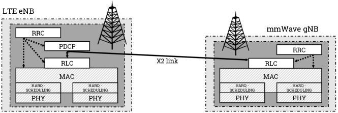
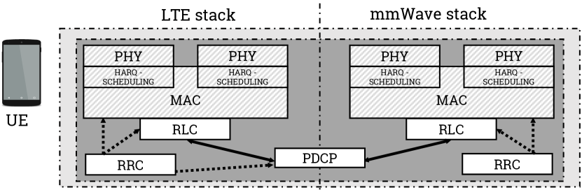
Given the importance of multi connectivity for mmWave networks, we believe that integrating enabling multi connectivity techniques in the mmWave module for ns-3 improves the realism and the validity of the performance evaluation of mmWave cellular networks. In the following sections we will present the multi connectivity solutions (i.e., multi RAT Dual Connectivity, and Carrier Aggregation) available in ns-3 mmWave111Multipath TCP can also be on top of different RATs, e.g., mmWave and LTE, or Wi-Fi, using Direct Code Execution (DCE) as described in (Mezzavilla et al., 2017; Polese et al., 2017c)., as shown by the protocol stack represented for the RAN side in Fig. 1 and the UE in Fig. 2.
3. Carrier Aggregation in ns-3 mmWave
The modeling of the CA feature in the mmWave module for ns-3 follows the 3GPP specifications for NR (3GPP, 2018c), and aligns the PHY and MAC design to the ns-3 LTE module implementation (Baldo et al., 2011), for which the CA capability was introduced in (Bojovic et al., 2017). In this section, we will describe the main characteristics of our implementation, and the differences with respect to CA in the LTE module.
As shown in Fig. 1 and Fig. 2, the implementation for the data plane involves the lower layers of the protocols stack (i.e., MAC and PHY), i.e., it is transparent with respect to the functionalities offered by the RLC and PDCP layers. The control functionalities are performed by the Radio Resource Control (RRC) layer, which is in charge of sharing the information for the carrier setup between the base station and the UE. In particular, the base station broadcasts information on the primary CC, and the UE connects to it. Then, when it enters the RRC_CONNECTED state, the base station RRC can instruct the UE to add and/or remove additional carriers with different parameters (3GPP, 2018c).
In our CA model, and as generally done in the ns-3 mmWave module (Mezzavilla et al., 2017), we inherit and extend the inter-layer interfaces of the LTE module (i.e., the Service Access Points (SAPs)) (Baldo et al., 2011) and the classes that implement them, in order to increase the flexibility and account for different channel and propagation conditions for the different carriers, as well as possibly different numerologies, as specified in (3GPP, 2018c).
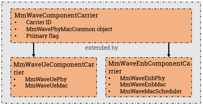
Similarly to the LTE implementation (Bojovic et al., 2017), the basic class of the CA implementation is the MmWaveComponentCarrier class and its MmWaveEnbComponentCarrier and MmWaveUeComponentCarrier extensions. An instance of this class represents a single carrier, and contains pointers to the associated protocol stack layers and relevant configurations, as shown in Fig. 3. In particular, in our implementation, a MmWaveComponentCarrier object contains a reference to a MmWavePhyMacCommon object, which is used to specify the numerology, frequency and bandwidth information for the carrier. The MmWavePhyMacCommon class was introduced in (Mezzavilla et al., 2015), and prior to the CA implementation, a single MmWavePhyMacCommon was created by MmWaveHelper during the configuration of the simulation. This object was shared by all the evolved Node Base (eNB) and UE PHY and MAC layer classes, as well as by the channel model classes, to provide access to a set of common parameters. With the CA implementation, instead, an instance of MmWavePhyMacCommon is created for each possible carrier, and is associated to the unambiguous identifier of the carrier (i.e., carrier ID stored in the m_componentCarrierId private variable of MmWavePhyMacCommon). Each of these objects is shared by all classes of the layers at the base station and UE side that are related to the same carrier. The carrier-specific MmWavePhyMacCommon instance then defines the carrier frequency (with the attribute CenterFreq), the bandwidth (for which it is possible to control the size of the resource blocks and their number) and the frame structure (i.e., the number of symbols per subframe, their duration, and the number of subframes per frame).
The different MmWaveComponentCarrier objects in the UEs and base stations are managed by a single CC manager, i.e., an object that implements respectively the LteUeComponentCarrierManager or the LteEnbComponentCarrierManager interfaces. The CC manager, together with the MmWaveUeMac or MmWaveEnbMac classes, models the functionalities of the MAC layer as show in Fig. 1 and Fig. 2 for the mmWave protocol stack. In particular, at the base station side, it receives the Buffer Status Reports (BSRs) from the RLC layers, and forwards them to the MmWaveScheduler instances following different policies according to the particular implementation of the CC manager. The schedulers then allocate the available resources and generate Downlink Control Informations (DCIs) for the different carriers. In the current implementation, the scheduling on the different carriers is independent, but we plan to extend it in order to model joint cross-carrier scheduling. The CC manager at the UE side is a simplified version of that of the base station, since it does not need to split the BSRs between the carriers, but limits itself to forwarding them to the base station CC manager. In particular, only the primary CC is used for the reporting of the BSRs and the exchange of control information222While implementing the CA feature for the mmWave module, we discovered a bug that prevents the CA implementation of the LTE module in ns-3.27 to use the resources allocated for the uplink. This bug is fixed in our implementation, and we proposed a patch also for LTE, see https://www.nsnam.org/bugzilla/show_bug.cgi?id=2861., since it is the only CC in which the Service Radio Bearers (SRBs) are set up.
In the mmWave CA implementation, we provide different implementations of the CC manager at the base station side. As for LTE, there is a MmWaveNoOpMacComponentCarrierManager which is used for single-carrier simulations, and a MmWaveRrMacComponentCarrierManager, which applies a round robin policy and splits the BSRs equally across the carriers, with the result that they reach a similar throughput. In addition, we include also a bandwidth-aware CC manager. It is likely that different carriers over different frequency bands will use different bandwidths, given that the higher the carrier frequency the larger the bandwidth that can be allocated to mobile network operators333For example, the International Telecommunication Union is considering the allocation to mobile operators of bands of approximatively 3 GHz in the 20–30 GHz spectrum, and of 10 GHz in the 60–80 GHz spectrum (Geneva, 2015).. Therefore, a typical use case for CA in the mmWave band would be the aggregation of a CC at relatively low carrier frequency, with a smaller bandwidth, but with better propagation properties (i.e., lower pathloss), and other CCs at much higher frequencies with larger bandwidths. In this case, a round robin CC manager that evenly splits the packets to be transmitted across the different carriers would not yield an optimal performance, given the different data rates that can be supported by the Congestion Controls (CCs). Therefore, the CC manager implemented in the MmWaveBaRrMacComponentCarrierManager class is made aware of the bandwidth available to the different carriers during the simulation setup, and then, when it receives the BSRs from the RLC layer instances in the base station or the UE, it divides the reports according to the bandwidth ratio across the carriers.
Another difference with respect to the LTE implementation is the usage of different channel model objects for the different carriers. In the mmWave module, indeed, the joint modeling of the propagation loss, the small and large scale fading and the beamforming has a fundamental importance for the accuracy of the simulation results. In our previous paper (Zhang et al., 2017) we introduced the implementation of the 3GPP channel model for frequencies above 6 GHz (3GPP, 2017a), which has features that depend on some carrier-specific parameters, such as the bandwidth and the carrier frequency. Therefore, we decided to use different MmWave3gppChannel objects444The MmWave3gppChannel class implements the SpectrumPropagationLossModel interface, and in particular the DoCalcRxPowerSpectralDensity method which applies fading and beamforming to the received power spectral density according to the 3GPP channel model and different beamforming techniques (Zhang et al., 2017). Moreover, in this current iteration, we support only the 3GPP channel model, but we plan to extend the implementation to all the channel models available in ns-3 mmWave. for each carrier, and use the MmWavePhyMacCommon of the carrier to set up the necessary parameters. Finally, we extended the MmWaveSpectrumValueHelper class in order to support the configuration (i.e., bandwidth, numerology and carrier frequency) of the different carriers.
CA configuration in ns-3 mmWave simulations
Thanks to the adoption of a MmWavePhyMacCommon object per carrier, the user of the ns-3 mmWave module has a lot of flexibility in configuring the parameters of the simulation. We provide two comprehensive simulation examples in the mmwave-ca-same-bandwidth.cc and mmwave-ca-diff-bandwidth.cc files in the examples folder of the mmWave module. The first step in the simulation configuration is the initialization of a MmWavePhyMacCommon per CC. The method SetAttribute can be used to set the relevant parameters for the carrier. Then, a map that associates the carrier ID to the MmWaveComponentCarrier is created, and passed as a parameter to the MmWaveHelper with the method SetCcPhyParams. The user then deploys the nodes, installs the relevant NetDevices, mobility models and applications as in a non-CA simulation script. It is the MmWaveHelper, indeed, that transparently takes care of the initialization of the channel objects and the association to the correct carrier, and of the setup of the mmWave base stations and UEs with the carriers information.
4. Dual Connectivity in ns-3 mmWave
The ns-3 mmWave module can also simulate UEs that can connect to two different RATs (i.e., LTE and mmWave base stations) at any given time. The modeling and the implementation of this functionality has been described in our previous works (Polese et al., 2016; Polese et al., 2017a; Polese, 2016). For the sake of completeness, we recall here the main features, and describe the changes needed to support CA.
The DC feature can be used to enhance the quality of the connection in two different ways, i.e., by increasing the reliability or the throughput. The reliability can be improved by using just the mmWave RAT and performing a seamless fallback to LTE when all the mmWave base stations are in outage. The throughput, instead, is increased by actively transmitting data on both the links. The implementation follows the 3GPP specifications for multi-RAT DC (3GPP, 2018b), and involves the higher layers of the protocol stack shown in Fig. 1 and Fig. 2, i.e., from the RLC layer up. The core of the implementation is a new NetDevice, i.e., the McUeNetDevice, which models a dual-stack (i.e., LTE and mmWave) UE with a single EpcUeNas class as the interface between the higher layers and the cellular protocol stack in the data plane.
In order to simulate a Non Stand Alone (NSA) deployment (i.e., a deployment of an LTE and of an NR RAN with a common LTE-EPC core network), the LTE eNB acts as the primary cell, i.e., as the mobility anchor towards the core network, and the NR Next Generation Node Base (gNB) at mmWave frequencies as the secondary cell. The MmWaveHelper class supports the installation of both LTE and mmWave base stations with the same EPC. The downlink packets for the UE are routed from the Packet Gateway (PGW) to the LTE eNB, and the integration happens at the PDCP layer: a single PDCP instance is created for each bearer, and controls two instances of the RLC layer, one in each cell. The X2 interface connects the different base stations, and is used to forward downlink PDCP Packet Data Units (PDUs) from the primary to the secondary, and vice versa for the uplink. In order to support this functionality, we introduced two classes that extends the LtePdcp class, i.e., McEnbPdcp at the RAN and McUePdcp at the UE side. We also defined new SAP interfaces, between the PDCP, the RLC layer and X2, which are configured during the bearer setup process in the RAN, in order to enable the packet forwarding to and from the remote RLC/PDCP as shown in Fig. 4.
The control plane was also extended in order to support DC. Contrary to the intra-RAT DC for LTE (3GPP, 2013), in the latest LTE-NR internetworking specifications (3GPP, 2018b) and in our implementation (Polese et al., 2016) both the LTE and NR mmWave stacks feature a complete implementation of the RRC layer. It performs control functionalities on the link such as initial access, collection and reporting of link measurements, bearer setup and management, mobility. The RRC layer in the LTE stack manages both the local link and the setup of the dual connectivity with the selected mmWave cell. We extended the implementation of the LteEnbRrc and LteUeRrc classes to support the DC functionalities, in particular for the new network procedures and the support of the split bearers.
o
The ns-3 mmWave DC also includes a fast handover procedure for the secondary cell (i.e., the one at mmWave), extensively described in (Polese et al., 2017a), that avoids the interaction with the core network during secondary cell updates and improves the performance of the mmWave RAN with mobile UEs by reducing the handover interruption time and the latency during handover events. Moreover, during the handover procedure, we support two different RLC buffer management policies. If RLC Acknowledged Mode (AM) is used, the handover is lossless, i.e., the PDUs in all the RLC buffers are forwarded from the source to the target cell. Instead, when Unacknowledged Mode (UM) is adopted, the handover is seamless, i.e., the source forwards to the targer cell only the RLC PDUs which have not yet been transmitted (Sesia et al., 2011; Nguyen et al., 2014).
With respect to the implementation described in (Polese et al., 2016), we extended the McUeNetDevice class in order to support carrier aggregation. Fig. 5 shows a simplified UML diagram of the integration of the DC and CA implementation for an McUeNetDevice and an LTE and a mmWave base stations. It can be seen that the mmWave and the LTE CA implementations are used respectively in the MmWaveEnbNetDevice and LteEnbNetDevice classes, while they coexist in the McUeNetDevice. The example in Fig. 5 shows two CCs per RAT, but it is actually possible to configure independently the number of CCs in the LTE and mmWave RATs. Then, given that different RRCs are in control of the LTE and mmWave links, it is possible to set the carriers after the UE has attached to either of the two RATs, using RRC connection reconfiguration messages.
5. Examples
In this section we describe two examples related to the application of CA to mmWave frequencies and report some relevant results that illustrate the flexibility of the CA implementation in configuring carrier-specific parameters and of the CC manager. They can be found in the files mmwave-ca-same-bandwidth.cc and mmwave-ca-diff-bandwidth.cc.
In the following examples, we always consider a total bandwidth of 1 GHz. However, we compare different scenarios in which one CC (with a fraction of the bandwidth) or the whole 1 GHz bandwidth is affected by additional blockage. The 3GPP channel model (3GPP, 2017a; Zhang et al., 2017), indeed, models different kinds of blockage phenomena. The main distinction is between the NLOS and LOS conditions, which differ because the main cluster of rays555The 3GPP 3D Spatial Channel Model (SCM) considers the received signal as a combination of different clusters, composed of multiple rays. Each cluster has its own angle of arrival and departure, delay with respect to the first cluster, and phase, and the total power is given by the aggregation of the power in the different clusters (3GPP, 2017a). is blocked or not, respectively. However, it is possible to model additional blockage events on the other clusters. This feature represents the attenuation that can be caused by (i) the human body of the user holding the device (self-blockage), or (ii) other external obstacles (non-self-blockage). The blockage is randomly applied in certain angular directions, and thus on the clusters whose angle of arrival or departure belongs to those regions. The per-cluster attenuation specified in the 3GPP model and in our implementation is of 30 dB (3GPP, 2017a), even though some recent papers proposed measurement-based models with a smaller attenuation (i.e., 15 dB) (Raghavan et al., 2018). The additional blockage can be set using the Blockage attribute of the MmWave3gppChannel class, and there is the possibility of selectively setting it carrier by carrier with the method SetBlockageMap of the MmWaveHelper class. In our performance evaluation, we consider that, if multiple carriers are used with different antenna arrays in the mobile device, then the user may just block one of them with his/her hand or body, while, if the whole bandwidth is allocated to a single carrier, then the link is either completely blocked or not.
In the first example, we consider a single user in a NLOS condition with respect to the serving mmWave base station. They exchange data both in downlink and uplink, using a full buffer condition at the RLC layer that saturates the capacity of the link (i.e., the RLC instance belongs to the class LteRlcSm). The user is placed at a 2D distance m from the base station, with an urban macro fading condition (3GPP, 2017a). In this example, we consider one or two CC using the same total amount of bandwidth. Therefore, if a single carrier is selected, it is configured with a bandwidth GHz, whereas, if two carriers are set up, each of them will use a bandwidth MHz. We also compare two CC deployment strategies. The first is a contiguous allocation in the GHz band, around a carrier frequency of 40 GHz. The second, instead, is a non-contiguous deployment with a CC at 32.5 GHz, in the GHz band, and the other at 73 GHz, in the GHz band (Geneva, 2015). The same number of antenna elements for both configurations is used at the base station (64) and at the UE (16).
The results are shown in Fig. 6(a) for the contiguous allocation, and in Fig. 6(b) for the other one. We only report the downlink throughput , since the results in uplink are similar given the frame structure adopted. It can be immediately seen that the usage of CA improves the RLC throughput in both cases. If CA is not used, and the whole 1 GHz bandwidth is controlled by a single scheduler, then it is not possible to properly adapt to different channel conditions that may be present in different chunks of the allocated bandwidth. The metric that is used to allocate the MCS, and consequently the transmission opportunities, is indeed based on the average SINR, and does not take into account frequency selective fading. With CA, instead, it is possible to assign different MCSs to each CC, that maximize the throughput while preventing packet loss, and different retransmission processes (3GPP, 2018c), so that each CC can optimally adjust to the different channel conditions. This can be observed also when comparing the contiguous allocation case in Fig. 6(a) with the non-contiguous one in Fig. 6(b). In the first configuration, the spectrum band of the scenarios with and without CA is the same (from 39.5 to 40.5 GHz), therefore the pathloss and fading parameters are similar. In the non-contiguous one, instead, one of the CCs or the only carrier if CA is not used are at 73 GHz. It can be seen that the CA manages to make up for the throughput loss given by the higher pathloss at 73 GHz, and that the gap between the scenarios with and without CA is larger in the non-contiguous configuration than in the contiguous. Finally, especially in the contiguous deployment scenario, the CA throughput is similar when the secondary CC is in blockage or not, corroborating the performance gain that can be achieved with a more agile resource allocation and channel adaptation mechanism.
The second example, instead, uses the bandwidth-aware scheduler, and compares the performance of different ratios between the bandwidth allocated to the different carriers. The CA deployment is in a contiguous spectrum band around the 40 GHz carrier. The user is randomly placed at a distance m and moves in the scenario with a random walk mobility model. Fig. 7 reports the downlink MAC-layer throughput of each carrier and the downlink RLC throughput. It can be seen that the performance worsen as the ratio decreases, and one of the two carriers occupies a much larger bandwidth than the other. For the secondary CC, whose bandwidth decreases with , the ratio between the throughput and the allocated bandwidth remains constant, while, for the primary, whose bandwidth increases with , the same ratio decreases. A configuration with a small is indeed similar to a configuration without CA for the primary CC, and does not provide the same channel adaptation capabilities as a configuration with a more even split of the bandwidth between the two CCs.
6. Conclusions
In this paper, we presented the first implementation of carrier aggregation for the ns-3 mmWave module, and the integration of CA with the LTE-NR dual connectivity feature. Multi connectivity is an important feature in mmWave cellular networks, since it helps increase the reliability of the mmWave link by providing macro diversity (i.e., the possibility of using multiple mmWave links with different frequencies and spatial characteristics) and a ready fallback to legacy networks at sub-6 GHz features. Therefore, modeling both CA and DC in the ns-3 mmWave module is an important contribution to the module, that makes it possible to simulate more complex, advanced and realistic scenarios666The code of the DC-CA implementation can be found at https://github.com/nyuwireless-unipd/ns3-mmwave/tree/ca-dc-integration.
After an overview on the multi connectivity options for mmWave in the literature and in the 3GPP or IETF specifications, we described the implementation of CA, focusing on the flexibility of the configuration of the parameters in the different carriers and on the implementation of a bandwidth-aware carrier manager. Then, we illustrated the DC implementation, with additional details on the integration with CA. Finally, we provided some examples and preliminary results for CA at mmWave frequencies, showing how CA improves the throughput of the network even if the same total bandwidth is considered, given the higher efficiency in performing the per-carrier scheduling and the macro diversity.
As future work, we plan to investigate additional CC manager policies, which could benefit from PHY-MAC cross-layer approaches, with additional channel information considered in the allocation of resources to the different carriers. Moreover, we will implement joint-carrier schedulers, to increase the efficiency of CA, and complete our implementation with a test suite.
References
- (1)
- 3GPP (2013) 3GPP. 2013. Study on Small Cell enhancements for E-UTRA and E-UTRAN. TR 36.842 (Rel. 12). (2013).
- 3GPP (2017a) 3GPP. 2017a. Study on channel model for frequency spectrum above 6 GHz. TR 38.900 (Rel. 14). (2017).
- 3GPP (2017b) 3GPP. 2017b. Study on New Radio Access Technology - Physical Layer Aspects. TR 38.802 (Rel. 14). (2017).
- 3GPP (2018a) 3GPP. 2018a. Evolved Universal Terrestrial Radio Access (E-UTRA) and Evolved Universal Terrestrial Radio Access Network (E-UTRAN); Overall description. TS 36.300 (Rel. 15). (2018).
- 3GPP (2018b) 3GPP. 2018b. Evolved Universal Terrestrial Radio Access (E-UTRA) and NR; Multi-connectivity. TS 37.340 (Rel. 15). (2018).
- 3GPP (2018c) 3GPP. 2018c. NR and NG-RAN Overall Description. TS 38.300 (Rel. 15). (2018).
- 3GPP (2018d) 3GPP. 2018d. Packet Data Convergence Protocol (PDCP) specification. TS 38.323 (Rel. 15). (2018).
- Baldo et al. (2011) Nicola Baldo, Marco Miozzo, Manuel Requena-Esteso, and Jaume Nin-Guerrero. 2011. An Open Source Product-oriented LTE Network Simulator Based on Ns-3. In Proceedings of the 14th ACM International Conference on Modeling, Analysis and Simulation of Wireless and Mobile Systems. 293–298.
- Boccardi et al. (2014) Federico Boccardi, Robert W. Heath Jr, Angel Lozano, Thomas L. Marzetta, and Petar Popovski. 2014. Five Disruptive Technology Directions for 5G. IEEE Commun. Mag. 52, 2 (Feb. 2014), 74–80.
- Bojovic et al. (2017) Biljana Bojovic, Melchiorre Danilo Abrignani, Marco Miozzo, Lorenza Giupponi, and Nicola Baldo. 2017. Towards LTE-Advanced and LTE-A Pro Network Simulations: Implementing Carrier Aggregation in LTE Module of Ns-3. In Proceedings of the Workshop on Ns-3 (WNS3 ’17). 63–70.
- Drago et al. (2018) M. Drago, T. Azzino, M. Polese, C. Stefanovic, and M. Zorzi. 2018. Reliable Video Streaming over mmWave with Multi Connectivity and Network Coding. In 2018 International Conference on Computing, Networking and Communications (ICNC). https://arxiv.org/abs/1711.06154
- Dutta et al. (2017) S. Dutta, M. Mezzavilla, R. Ford, M. Zhang, S. Rangan, and M. Zorzi. 2017. Frame Structure Design and Analysis for Millimeter Wave Cellular Systems. IEEE Transactions on Wireless Communications 16, 3 (Mar. 2017), 1508–1522.
- Ford et al. (2013) A. Ford, C. Raiciu, M. Handley, and O. Bonaventure. 2013. TCP Extensions for Multipath Operation with Multiple Addresses. RFC 6824.
- Ford et al. (2016) Russell Ford, Menglei Zhang, Sourjya Dutta, Marco Mezzavilla, Sundeep Rangan, and Michele Zorzi. 2016. A Framework for End-to-End Evaluation of 5G mmWave Cellular Networks in ns-3. In Proceedings of the Workshop on ns-3. ACM, 85–92.
- Geneva (2015) ITU-R World Radiocommunication Conference Geneva. 2015. Studies on frequency-related matters for International Mobile Telecommunications identification including possible additional allocations to the mobile services on a primary basis in portion(s) of the frequency range between 24.25 and 86 GHz for the future development of International Mobile Telecommunications for 2020 and beyond. Resolution 238 (WRC-15). (2015). https://www.itu.int/dms_pub/itu-r/oth/0c/0a/R0C0A00000C0014PDFE.pdf
- Khan et al. (2014) Z. Khan, H. Ahmadi, E. Hossain, M. Coupechoux, L. A. Dasilva, and J. J. Lehtomäki. 2014. Carrier aggregation/channel bonding in next generation cellular networks: methods and challenges. IEEE Network 28, 6 (Nov 2014), 34–40.
- M. Giordani, M. Mezzavilla, S. Rangan, M. Zorzi (2017) M. Giordani, M. Mezzavilla, S. Rangan, M. Zorzi. 2017. An Efficient Uplink Multi-Connectivity Scheme for 5G mmWave Control Plane Applications. Submitted to IEEE Transaction on Wireless Communications (TWC) (2017). https://arxiv.org/abs/1610.04836
- Maamari et al. (2016) D. Maamari, N. Devroye, and D. Tuninetti. 2016. Coverage in mmWave Cellular Networks With Base Station Co-Operation. IEEE Transactions on Wireless Communications 15, 4 (April 2016), 2981–2994. DOI:http://dx.doi.org/10.1109/TWC.2016.2514347
- MacCartney Jr et al. (2017) George R MacCartney Jr, Theodore S Rappaport, and Amitava Ghosh. 2017. Base Station Diversity Propagation Measurements at 73 GHz Millimeter-Wave for 5G Coordinated Multipoint (CoMP) Analysis. In 2017 IEEE Globecom Workshops (GC Wkshps).
- Mezzavilla et al. (2015) Marco Mezzavilla, Sourjya Dutta, Menglei Zhang, Mustafa Riza Akdeniz, and Sundeep Rangan. 2015. 5G mmWave Module for the ns-3 Network Simulator. In Proceedings of the 18th ACM International Conference on Modeling, Analysis and Simulation of Wireless and Mobile Systems. 283–290.
- Mezzavilla et al. (2017) Marco Mezzavilla, Menglei Zhang, Michele Polese, Russell Ford, Sourjya Dutta, Sundeep Rangan, and Michele Zorzi. 2017. End-to-End Simulation of 5G mmWave Networks. submitted to IEEE Communication Surveys & Tutorials (2017). https://arxiv.org/abs/1705.02882
- Nguyen et al. (2014) Binh Nguyen, Arijit Banerjee, Vijay Gopalakrishnan, Sneha Kasera, Seungjoon Lee, Aman Shaikh, and Jacobus Van der Merwe. 2014. Towards Understanding TCP Performance on LTE/EPC Mobile Networks. In Proceedings of the 4th Workshop on All Things Cellular: Operations, Applications, and Challenges (AllThingsCellular ’14). ACM, 41–46.
- Pedersen et al. (2011) K. I. Pedersen, F. Frederiksen, C. Rosa, H. Nguyen, L. G. U. Garcia, and Y. Wang. 2011. Carrier aggregation for LTE-advanced: functionality and performance aspects. IEEE Communications Magazine 49, 6 (June 2011), 89–95.
- Pi and Khan (2011) Z. Pi and F. Khan. 2011. An introduction to millimeter-wave mobile broadband systems. IEEE Communications Magazine 49, 6 (June 2011), 101–107.
- Polese (2016) Michele Polese. 2016. Performance Comparison of Dual Connectivity and Hard Handover for LTE-5G Tight Integration in mmWave Cellular Networks. Master’s thesis. Department of Information Engineering, University of Padova. Available at http://arxiv.org/abs/1607.04330.
- Polese et al. (2017a) M. Polese, M. Giordani, M. Mezzavilla, S. Rangan, and M. Zorzi. 2017a. Improved Handover Through Dual Connectivity in 5G mmWave Mobile Networks. IEEE Journal on Selected Areas in Communications 35, 9 (Sept 2017), 2069–2084.
- Polese et al. (2017b) M. Polese, R. Jana, and M. Zorzi. 2017b. TCP and MP-TCP in 5G mmWave Networks. IEEE Internet Computing 21, 5 (Sep. 2017), 12–19.
- Polese et al. (2017c) Michele Polese, Rittwik Jana, and Michele Zorzi. 2017c. TCP in 5G mmWave Networks: Link Level Retransmissions and MP-TCP. In IEEE Conference on Computer Communications Workshops (INFOCOM WKSHPS). IEEE, 343–348.
- Polese et al. (2016) Michele Polese, Marco Mezzavilla, and Michele Zorzi. 2016. Performance Comparison of Dual Connectivity and Hard Handover for LTE-5G Tight Integration. In Proceedings of the 9th EAI International Conference on Simulation Tools and Techniques (SIMUTOOLS’16). 118–123.
- Raghavan et al. (2018) Vasanthan Raghavan, Lida Akhoondzadeh-Asl, Vladimir Podshivalov, Joakim Hulten, M Ali Tassoudji, Ozge Hizir Koymen, Ashwin Sampath, and Junyi Li. 2018. Statistical Blockage Modeling and Robustness of Beamforming in Millimeter Wave Systems. arXiv preprint arXiv:1801.03346 (2018).
- Rangan et al. (2014) S. Rangan, T. S. Rappaport, and E. Erkip. 2014. Millimeter-Wave Cellular Wireless Networks: Potentials and Challenges. Proc. IEEE 102, 3 (Mar. 2014), 366–385.
- Rappaport et al. (2013) Theodore S Rappaport, Shu Sun, Rimma Mayzus, HANG Zhao, Yaniv Azar, Kevin Wang, George N Wong, Jocelyn K Schulz, Matthew Samimi, and Felix Gutierrez. 2013. Millimeter Wave Mobile Communications for 5G Cellular: It Will Work! IEEE Access 1 (May 2013), 335–349.
- Roh et al. (2014) Wonil Roh, Ji-Yun Seol, and et al. 2014. Millimeter-wave beamforming as an enabling technology for 5G cellular communications: theoretical feasibility and prototype results. IEEE Communications Magazine 52, 2 (Feb. 2014), 106 – 113.
- Saha et al. (2017) Swetank Kumar Saha, Roshan Shyamsunder, Naveen Muralidhar Prakash, Hany Assasa, Adrian Loch, Dimitrios Koutsonikolas, and Joerg Widmer. 2017. Poster: Can MPTCP Improve Performance for Dual-Band 60 GHz/5 GHz Clients?. In Proceedings of the 23rd Annual International Conference on Mobile Computing and Networking. ACM, 573–575.
- Sesia et al. (2011) Stefania Sesia, Matthew Baker, and Issam Toufik. 2011. LTE-the UMTS long term evolution: from theory to practice. John Wiley & Sons.
- Shafi et al. (2017) M. Shafi, A. F. Molisch, P. J. Smith, T. Haustein, P. Zhu, P. De Silva, F. Tufvesson, A. Benjebbour, and G. Wunder. 2017. 5G: A Tutorial Overview of Standards, Trials, Challenges, Deployment, and Practice. IEEE Journal on Selected Areas in Communications 35, 6 (June 2017), 1201–1221.
- Shokri-Ghadikolaei et al. (2015) H. Shokri-Ghadikolaei, C. Fischione, G. Fodor, P. Popovski, and M. Zorzi. 2015. Millimeter Wave Cellular Networks: A MAC Layer Perspective. IEEE Trans. Comm. 63, 10 (Oct. 2015), 3437–3458.
- Silva et al. (2015) I. Da Silva, G. Mildh, J. Rune, P. Wallentin, J. Vikberg, P. Schliwa-Bertling, and R. Fan. 2015. Tight Integration of New 5G Air Interface and LTE to Fulfill 5G Requirements. In IEEE 81st Vehicular Technology Conference (VTC Spring).
- Sun et al. (2014) S. Sun, T. S. Rappaport, R. W. Heath, A. Nix, and S. Rangan. 2014. MIMO for millimeter-wave wireless communications: beamforming, spatial multiplexing, or both? Communications Magazine, IEEE 52, 12 (Dec. 2014), 110–121.
- Tazaki et al. (2013) Hajime Tazaki, Emilio Mancini, Daniel Camara, Thierry Turletti, and Walid Dabbous. 2013. MSWIM Demo Abstract: Direct Code Execution: Increase Simulation Realism Using Unmodified Real Implementations. In Proceedings of the 11th ACM International Symposium on Mobility Management and Wireless Access (MobiWac ’13). 29–32.
- Tesema et al. (2017) Fasil B Tesema, Ahmad Awada, Ingo Viering, Meryem Simsek, and Gerhard P Fettweis. 2017. Multiconnectivity for Mobility Robustness in Standalone 5G Ultra Dense Networks with Intrafrequency Cloud Radio Access. Wireless Communications and Mobile Computing 2017 (Jan. 2017).
- Zhang et al. (2017) Menglei Zhang, Michele Polese, Marco Mezzavilla, Sundeep Rangan, and Michele Zorzi. 2017. ns-3 Implementation of the 3GPP MIMO Channel Model for Frequency Spectrum Above 6 GHz. In Proceedings of the Workshop on ns-3. ACM, 71–78.
- Zhang et al. (2015) R. Zhang, M. Wang, L. X. Cai, Z. Zheng, X. Shen, and L. L. Xie. 2015. LTE-unlicensed: the future of spectrum aggregation for cellular networks. IEEE Wireless Communications 22, 3 (June 2015), 150–159.