Spin and charge pumping by steady or pulse current-driven magnetic domain wall: A self-consistent multiscale time-dependent-quantum/time-dependent-classical approach
Abstract
We introduce a multiscale framework which combines time-dependent nonequilibrium Green function (TD-NEGF) algorithms, scaling linearly in the number of time steps and describing quantum-mechanically conduction electrons in the presence of time-dependent fields of arbitrary strength or frequency, with classical time evolution of localized magnetic moments described by the Landau-Lifshitz-Gilbert (LLG) equation. The TD-NEGF+LLG framework can be applied to a variety of problems where current-driven spin torque induces dynamics of magnetic moments as the key resource for next generation spintronics. Previous approaches to such nonequilibrium many-body system (like steady-state-NEGF+LLG framework) neglect noncommutativity of a quantum Hamiltonian of conduction electrons at different times and, therefore, the impact of time-dependent magnetic moments on electrons leading to pumping of spin and charge currents. The pumped currents can, in turn, self-consistently affect the dynamics of magnetic moments themselves. Using magnetic domain wall (DW) as an example, we predict that its motion will pump time-dependent spin and charge currents (on the top of unpolarized DC charge current injected through normal metal leads to drive the DW motion), where the latter can be viewed as a realization of quantum charge pumping due to time-dependence of the Hamiltonian and left-right symmetry breaking of the two-terminal device structure. The conversion of AC components of spin current, whose amplitude increases (decreases) as the DW approaches (distances from) the normal metal lead, into AC voltage via the inverse spin Hall effect offers a tool to precisely track the DW position along magnetic nanowire. We also quantify the DW transient inertial displacement due to its acceleration and deceleration by pulse current and the entailed spin and charge pumping. Finally, TD-NEGF+LLG as a nonperturbative (i.e., numerically exact) framework allows us to establish the limits of validity of the so-called spin-motive force (SMF) theory for pumped charge current by time-dependent magnetic textures—the perturbative analytical formula of SMF theory becomes inapplicable for large frequencies (but unrealistic in magnetic system) and, more importantly, for increasing noncollinearity when the angles between neighboring magnetic moments exceed .
The current-driven dynamics of collinear, such as macrospin Ralph2008 ; Berkov2008 ; Xiao2005 , and noncollinear, such as domain walls (DWs) Tatara2008 ; Yamaguchi2004 ; Kim2017a ; Lee2004a ; Baumgartner2017 and skyrmions Nagaosa2013 ; Fert2013 , textures of localized magnetic moments are both a fundamental problem for nonequilibrium quantum many-body physics and a key resource for next generation spintronics Locatelli2014 ; Kent2015 ; Grollier2016 ; Borders2017 . For example, the current-driven spin torque induced magnetization dynamics in magnetic tunnel junctions (MTJs) Ralph2008 ; Berkov2008 or ferromagnet/spin-orbit-coupled-material bilayers Baumgartner2017 ; Manchon2018 ; Nikolic2018 can implement variety of functionalities, such as nonvolatile magnetic random access memories (MRAM), microwave oscillators, microwave detectors, spin-wave emitters, memristors and artificial neural networks Locatelli2014 ; Kent2015 ; Grollier2016 ; Borders2017 . The spin torque can also move DWs and skyrmions along magnetic nanowires which underlies racetrack Parkin2008 ; Parkin2015 and skyrmionic memories Koshibae2015 , respectively, with potentially ultralow energy consumption.
The theoretical analysis of these phenomena requires to account for the interaction of fast conduction electrons, described quantum-mechanically, with slow magnetic moments whose dynamics can be captured by the classical Landau-Lifshitz-Gilbert (LLG) equation Berkov2008 ; Stiles2007 ; Evans2014 . However, quantum transport studies of spin torque in spin-valves Haney2007 ; Wang2008b ; Yu2017 ; Nikolic2018 , MTJs Theodonis2006 ; Heiliger2008 ; Stamenova2017 and DWs Zhang2004a ; Garate2009 ; Balaz2012 ; Waintal2004 ; Xiao2006a ; Tatara2007 ; Yuan2016a are typically confined to computing torque of steady current of electrons acting on a chosen static configuration of localized magnetic moments. Similarly, standard simulations of current-driven magnetization dynamics Xiao2005 ; Berkov2008 or motion of DWs Baumgartner2017 ; Lee2004a ; Stiles2007 ; Li2004 ; Li2004a ; Thiaville2005 ; Thiaville2007 ; Martinez2009 ; Boone2010 ; Chureemart2011 and skyrmions Iwasaki2013a ; Sampaio2013 evade explicit modeling of the flow of conduction electrons by using only classical micromagnetics into which one has to introduce phenomenological terms to describe the so-called adiabatic (when propagating electron spins remain mostly aligned or antialigned with the localized magnetic moments) and nonadiabatic (which can have local Zhang2004a ; Garate2009 ; Balaz2012 and nonlocal Waintal2004 ; Xiao2006a ; Tatara2007 contributions) spin torques due to flowing electrons. Deriving additional torque expressions is required in the presence of spin-orbit coupling Knoester2014 ; Hals2014 or nontrivial topology Braun2012 of magnetic textures Akosa2017 .
A handful of studies Ohe2006a ; Ohe2006b ; Salahuddin2006 ; Xie2017 ; Ellis2017 have also attempted to develop a multiscale combination of computational quantum (or even simpler semiclassical Akosa2015 ; Claudio-Gonzalez2012 ; Lee2013a ; Sturma2016 ) transport of conduction electrons with discretized LLG equation for the motion of localized magnetic moments described by the classical vectors . However, these attempts employ steady-state nonequilibrium density matrix, strictly applicable only to systems which do not evolve in time, which can be expressed in terms of the lesser Green function of the nonequilibrium Green function (NEGF) formalism Stefanucci2013
| (1) |
Thus, such NEGF+LLG approach Ohe2006a ; Ohe2006b ; Salahuddin2006 ; Xie2017 ; Ellis2017 naively assumes that electrons respond instantaneously to time-dependent potential introduced into the quantum Hamiltonian of the conduction electrons by the time evolution of , thereby neglecting noncommutativity of the quantum Hamiltonian at different times. On the other hand, it is well-known that even infinitely slow dynamics of can pump spin currents Tserkovnyak2005 ; Chen2009 , as well as charge current if additional conditions are satisfied Chen2009 ; Hals2010 ; Mahfouzi2012 . Therefore, using NEGF+LLG approach precludes taking into account self-consistent feedback Lee2013a ; Kim2012b where the dynamics of leads to pumped spin currents which, in turn, can exert additional torque and time-retarded damping (with microscopically Sayad2015 ; Hammar2016 rather than phenomenologically Bose2011 ; Thonig2015 determined memory kernel) on thereby modifying its dynamics. Finally, time-dependent quantum treatment of electrons is required to describe pulse-current-induced dynamics of which is of paramount importance in basic research experiments Baumgartner2017 and, e.g., racetrack memory applications Parkin2008 ; Parkin2015 where usage of current pulses Thomas2006 or their trains Thomas2007 reduces threshold current density to move the DW while precise control of the DW position can be achieved by tailoring pulse duration and shape Thiaville2007 ; Thomas2010 ; Chauleau2010 ; Taniguchi2015 ; Pivano2017 .
Taking into account these effects demands to construct the time-dependent nonequilibrium density matrix, , which can be accomplished using the time-dependent NEGF (TD-NEGF) framework Stefanucci2013 ; Gaury2014
| (2) |
where the lesser Green function depends on two-times in arbitrary nonequilibrium situations Stefanucci2013 [in steady-state nonequilibrium it depends on , so it can be Fourier transformed to energy, as utilized in Eq. (1)]. Within such more general framework, NEGF+LLG approach corresponds to taking just the lowest order of expanded in power series in small Mahfouzi2016 ; Bode2012 , so that and are assumed to depend only parametrically on time and are effectively computed for the frozen-in-time configuration of . For instance, the neglected first order correction contains information about the Gilbert damping term in the LLG equation Mahfouzi2016 ; Bode2012 .
The nonequilibrium density matrix yields expectation value of any physical quantity, such as the current-driven (CD) part of nonequilibrium spin density
| (3) | |||||
For a given quantum Hamiltonian of conduction electron subsystem, computing microscopically generates all relevant spin torque terms in the LLG equation for . In Eq. (3), is the vector of the Pauli matrices, and one has to subtract Nikolic2018 ; Mahfouzi2013 any nonzero equilibrium spin density (present in the absence of current) by using the NEGF expression for the equilibrium density matrix Stefanucci2013 ,
| (4) |
where is the retarded Green function (GF) in equilibrium and is the Fermi distribution function (identical for both reservoirs in equilibrium)
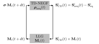

In this study, we develop a numerically exact [i.e., equivalent to summing all terms in the above mentioned power series expansion of ] approach denoted as TD-NEGF+LLG. As explained schematically in Fig. 2, TD-NEGF+LLG employs in Eq. (2) to obtain via Eq. (3); which is then coupled to the LLG equation for ; which, in turn, is used to obtain at the next time step. The paper is organized as follows. The details of TD-NEGF+LLG framework are introduced in Sec. I. To demonstrate richness of novel insights made possible by this framework, we apply it to widely studied Tatara2008 ; Lee2004a ; Stiles2007 ; Li2004 ; Li2004a ; Thiaville2005 ; Thiaville2007 ; Martinez2009 ; Boone2010 ; Chureemart2011 ; Pivano2017 problem of current-driven DW motion along clean magnetic nanowire attached to two normal metal (NM) leads, where the injected unpolarized charge current from the NM leads is steady in Sec. II or pulsed in Sec. IV. In Sec. III, we employ a toy system of three precessing noncollinear spins to compare nonperturbative results from TD-NEGF for pumped charge current by this system to predictions of a perturbative analytical formula of the so-called spin-motive force (SMF) theory Barnes2007 ; Zhang2009b for time-dependent magnetization textures, thereby delineating the limits of its validity. We conclude in Sec. V.
I TD-NEGF+LLG framework
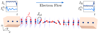
To make the discussion transparent, we use an example of a Néel DW illustrated in Fig. 1 and described by a smooth function Ohe2006a of the position of site along the -axis,
| (5) |
Its localized magnetic moments lie entirely in the plane when the current is zero. Here is the coordinate of the DW center and is its width (in the units of the lattice spacing ). The interaction between localized magnetic moments, whose direction at site is specified by unit vector while their magnitude is , is described by the classical Hamiltonian
| (6) | |||||
Besides Heisenberg term with exchange interaction between the nearest neighbors of strength eV, this includes - interaction between conduction electrons and localized magnetic moments of strength eV; magnetic anisotropy (along the -axis) of strength eV; and demagnetization (along the -axis) of strength meV (corresponding to the demagnetizing field of T). The Hamiltonian in Eq. (6) determines the effective magnetic field acting on each localized magnetic moment, , which is inserted into the atomistic LLG equation (for simplicity, without noise term required at nonzero temperature) Stiles2007 ; Evans2014 ; Chureemart2011
| (7) |
Here is the gyromagnetic ratio and the intrinsic Gilbert damping parameter Gilmore2007 is chosen as found in many realistic magnetic nanowires Thiaville2005 ; Thiaville2007 ; Taniguchi2015 . Such coupled LLG equations are solved by the Heun numerical scheme Evans2014 .
The conduction electron subsystem is described by the quantum Hamiltonian for a one-dimensional (1D) tight-binding (TB) model of a magnetic nanowire
| (8) |
where is a row vector containing operators which create an electron with spin at site ; is a column vector containing the corresponding annihilation operators; and eV is the nearest-neighbor hopping. The TB chain described by Eq. (8) is attached [Fig. 1] to two semi-infinite normal metal (NM) leads, modeled by the same Hamiltonian in Eq. (8) but with . We inject through the NM leads conventional unpolarized charge current using either DC bias voltage , applied as electrochemical potential difference, and between the macroscopic reservoirs into which the left (L) and right (R) leads are assumed to terminate, or voltage pulses of different shape (see Fig. 8 for illustration) whose amplitude is the same as the DC bias voltage. We quote the Fermi energy with respect to the bottom of the band of the NM leads.
The Hamiltonian in Eq. (8) contains time-dependent term due to supplied [Fig. 2] by solving the system of LLG equations displayed as Eq. (7). Thus, rigorously it must be treated by some approach of time-dependent nonequilibrium quantum statistical mechanics which can yield in Fig. 2. The TD-NEGF formalism Stefanucci2013 ; Gaury2014 offers a route to , as shown in Eq. (2). It operates with two fundamental quantities Stefanucci2013 —the retarded and the lesser GFs which describe the density of available quantum states and how electrons occupy those states, respectively. For the device in Fig. 1 we solve a matrix integro-differential equation Croy2009 ; Popescu2016
| (9) |
which can be viewed as the exact master equation for an open finite-size quantum system, described by , which is attached via semi-infinite leads to much larger macroscopic reservoirs. We use convention in which bold-face symbols denote matrices in orbitalspin vector space, where the size of the orbital space is equal to the number of sites (–50 is chosen for the central magnetic nanowire region in Fig. 1) and the size of the spin space is two. The matrix
| (10) |
is expressed in terms of the lesser/greater GF and the corresponding lesser/greater self-energies Stefanucci2013 , whose numerical construction in order to convert Eq. (9) into a system of ordinary differential equations can be found in Ref. Popescu2016 . Equation (10) yields charge current in lead of the device,
| (11) |
as well as spin currents
| (12) |
We use the same units for both types of current— and —defined in terms of spin-resolved charge currents for along the -axis. The local (bond) charge current Nikolic2006 between sites and is computed as
| (13) |
and the local spin currents are given by
| (14) |
The computational complexity of TD-NEGF calculations stems from the memory effect—the entire history must be stored in order to accurately evolve the NEGFs. For efficient calculation over long times and for large number of simulated sites, we employ newly developed TD-NEGF algorithms Croy2009 ; Popescu2016 which scale linearly Gaury2014 in the number of time steps.
We also compare our TD-NEGF+LLG framework to related efforts toward hybrid time-dependent-quantum/time-dependent-classical description of systems where conduction electrons interact with classical localized magnetic moments. Such an approach introduced in Ref. Sayad2015 has the same feedback loop illustrated in Fig. 2, but it considers electronic subsystems as a closed quantum system (e.g., as described by finite length TB chain Sayad2015 ) whose master equation in Eq. (9), therefore, does not contain second term on the right-hand side. This makes it unsuitable for modeling of spintronic devices where one has to inject or collect spin and charge current through the attached semi-infinite leads. They also play an essential role by converting discrete spectrum of the central region into a continuous one, which ensures that current reaches steady-state in the long time limit after DC bias voltage is applied, even without explicit modeling of inelastic scattering processes. The approach of Ref. Hammar2016 does include semi-infinite leads and macroscopic reservoirs into which they terminate, but it executes variety of approximations to make possible analytical solution for junctions containing a single classical localized spin, so it is not suitable for spatially extended spintronic devices with many coupled classical spins which require numerical modeling. The quantum part of both approaches Sayad2015 ; Hammar2016 generates effectively a non-Markovian LLG equation due to additional time-retarded damping, on the top of intrinsic Gilbert damping (arising from combined effects of spin-orbit coupling and electron-phonon interaction Gilmore2007 ) that we take into account by using nonzero in Eq. (7). Our TD-NEGF+LLG framework also contains time-retarded damping whose memory kernel properties will be discussed in future studies.
II DW motion driven by steady current: Spin and charge pumping
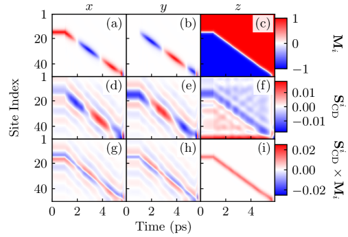
Evolving via Eq. (9) requires time step fs for numerical stability. The spatio-temporal profile of shown in Fig. 3(d)–(f) is obtained by plugging in thus evolved into Eq. (3). This is supplied to a system of LLG equations for , whose spatio-temporal profile is shown in Fig. 3(a)–(c), where we use the same time step fs. The noncollinearity at a given time between [Fig. 3(d)–(f)] and [Fig. 3(a)–(c)] generates spin torque on the DW ( and determine damping-like torque and determines field-like torque Ralph2008 ; Nikolic2018 ) whose spatio-temporal profile is shown in Fig. 3(g)–(i). Figure 3(b), as well as movies showing complete time evolution of in the Supplemental Material sm , demonstrate how current-induced spin torque distorts moving DW with respect to the equilibrium Néel configuration by generating nonzero component.
Since TD-NEGF also captures transient charge and spin currents after the DC bias voltage is turned on at , we first evolve conduction electron subsystem (during ps in Fig. 3) with fixed DW (i.e., without coupling to LLG equations) until such currents become steady. This ensures that at ps, when LLG dynamics is turned on, spatial profile of computed by TD-NEGF and NEGF formalisms are identical. The position of the DW center as a function of time in Fig. 4 computed by NEGF+LLG is similar to LLG result obtained in Fig. 1 of Ref. Stiles2007 . On the other hand, it differs from LLG results of Ref. Li2004 ; Li2004a and related NEGF+LLG results of Ref. Ohe2006a where becomes saturated after relatively short time (i.e., DW motion comes quickly to a halt) for , while DW continues to move for with exhibiting high-frequency oscillations (i.e., regularly accelerating and slowing down of the DW) due to the excitation of the spin waves Li2004a ; Ohe2006a . This discrepancy could be due to time-retarded damping Sayad2015 ; Hammar2016 , present in TD-NEGF+LLG but absent in NEGF+LLG framework, which can affect strongly Bose2011 spin-wave excitation. Most importantly, TD-NEGF+LLG framework predicts faster DW motion in Fig. 4 when compared to our NEGF+LLG results. This can be explained by additional torque exerted onto the DW by the pumped Tserkovnyak2005 ; Chen2009 spin currents of electrons in the presence of localized magnetic moment precession, as depicted in the movies in the Supplemental Material sm , which is a purely time-dependent quantum-mechanical effect absent in either LLG or NEGF+LLG simulations. Although the difference between the TD-NEGF+LLG and NEGF+LLG results in Fig. 4 is small over ps time interval considered, a much larger one can be extrapolated as one approaches ns typical time of DW motion in experiments and applications Thomas2006 ; Thomas2007 ; Thomas2010 ; Chauleau2010 ; Taniguchi2015 .
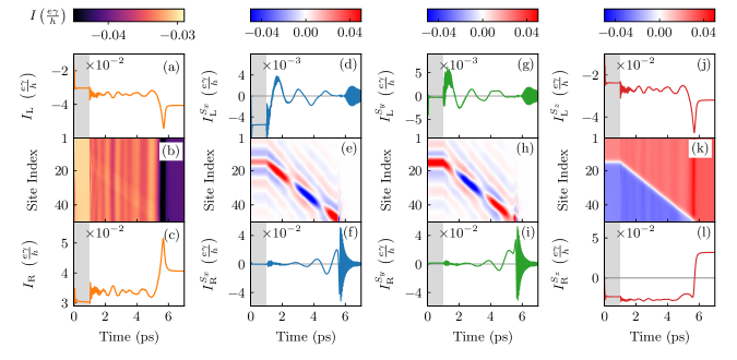
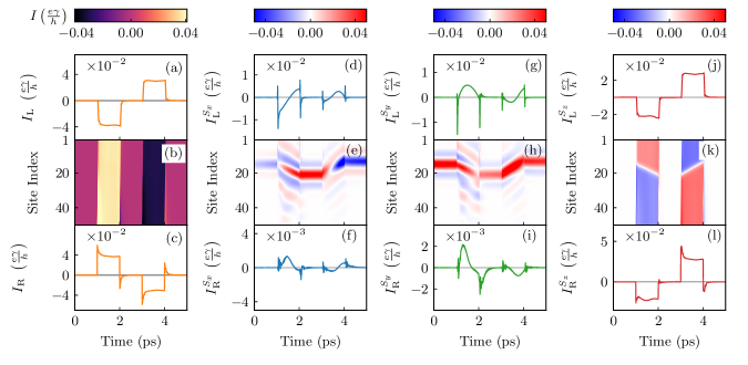
The TD-NEGF+LLG framework allows us to obtain explicitly time-dependent charge [Fig. 5(a),(c)] and spin [Fig. 5(d),(g),(j),(f),(i),(l)] currents flowing into the NM leads in the course of DW motion, as well as spatio-temporal profiles of bond charge [Fig. 5(b)] and bond spin [Fig. 5(e),(h),(k)] currents flowing between the nearest-neighbor sites. Note that these time-dependent currents are superimposed on the background of injected DC charge current, or DC spin current generated by spin-polarizing effect of the localized magnetic moments on injected DC current (the background values can be read from the flat lines within ps interval in Fig. 5).
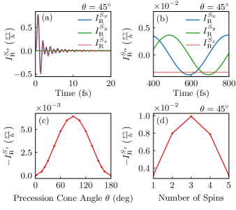
Since movies of time evolution of in the Supplemental Material sm show that three localized magnetic moments around the propagating DW center are precessing, to gain intuition about how they induce spin and charge pumping in Fig. 5 we first examine the simplest example of a single [Fig. 6(a)–(c)] or up to five [Fig. 6(d) magnetic moments precessing steadily with frequency and precession cone angle while being coupled to an infinite 1D TB chain Chen2009 . Such setup—precessing spins in the center of 1D TB chain (for illustration see Fig. 1 in Ref. Chen2009 )—pumps only spin currents in both directions, as shown in Fig. 6(b). This problem is exactly solvable in the rotating frame, where our result in Fig. 6(b), after transient currents in Fig. 6(a) die away, matches analytical formula derived in Ref. Chen2009 , thereby also validating the accuracy of TD-NEGF numerical calculations. In particular, time-independent in Fig. 6(c) exhibits standard dependence Tserkovnyak2005 on the precession cone angle . The maximum output in Fig. 5(d) is achieved by using three magnetic moments precessing together, which signifies interfacial nature Tserkovnyak2005 ; Chen2009 of spin pumping.
In addition, even single precessing magnetic moment can pump charge current with nonzero DC component on the proviso that the key requirement in the theory of quantum charge pumping by a time-dependent fields is satisfied Vavilov2001 ; Moskalets2002 ; FoaTorres2005 ; Bajpai2018 —breaking of left-right symmetry. This requires to break inversion symmetry and/or time-reversal symmetry. If both inversion and time-reversal symmetries are broken dynamically, the DC component of pumped charge current is at low frequencies, as found in standard example of quantum dot attached to two leads and exposed to two spatially separated potentials oscillating out-of-phase Vavilov2001 ; Moskalets2002 . If only one of those two symmetries is broken, and this does not have to occur dynamically, the DC component of the pumped current at low frequencies, as found in the case of single precessing magnetic moment with static potential barrier (breaking inversion symmetry) introduced into the 1D TB chain hosting the magnetic moment Chen2009 .
Armed with this intuition, we can interpret currents in Fig. 5(b),(e),(h),(k) as the consequence of moving DW center pumping spin and charge currents due to the dynamics of magnetic moments around the DW center depicted in the movies in the Supplemental Material sm . The pumped charge current arises because the DW itself breaks the left-right symmetry while localized magnetic moments around its center are driven into precession by spin torque, as visualized in Fig. 3. The collision of the DW with the right NM lead results in its annihilation, i.e., all eventually point along the -axis, which generates spike in the charge and spin currents in Fig. 5 around ps.
While variety of techniques have been developed to determined the position of a moving DW Kim2017a ; Singh2010 ; Krzysteczko2017 , they often have limitations in resolution or acquisition speed Krzysteczko2017 . Figure 5 shows that temporal profiles of and are tightly correlated with the DW position, as well as that their amplitude increases (decreases) as the DW approaches (distances from) the NM lead. Thus, converting these spin currents into AC voltage via the inverse spin Hall effect, which can be done experimentally with high efficiency Wei2014 , offers an electrical measurement that precisely tracks the position of a single DW propagating along magnetic nanowire.
III TD-NEGF+LLG vs. spin-motive force theory for charge current pumped by time-dependent magnetic textures
The spin-motive force (SMF) Barnes2007 ; Zhang2009b ; Kim2012b ; Berger1986 ; Volovik1987 ; Stern1992 ; Saslow2007 ; Duine2008 ; Tserkovnyak2008a ; Liu2011e ; Lucassen2011 ; Yamane2011 ; Hals2015 refers to pumping of charge and spin currents, or generation of voltage associated with pumped charge current, by time-dependent noncoplanar and noncollinear magnetic textures within conducting ferromagnets. In contrast to conventional electromotive force induced by change of magnetic flux through a circuit in accord with Faraday law of classical electromagnetism, SMF originates from spin and can appear even in static uniform external magnetic field (as long as such field generates dynamics of localized magnetic moments). The SMF has been invoked to explain experimental detection of electric voltage due the motion of magnetic DW Yang2009 , magnetization reversal of nano-particles embedded in a MTJ Hai2009 and gyration of magnetic vortex core Tanabe2012 . Thus, SMF phenomenon is certainly related to charge current pumping explored in Sec. II, and in this Section we investigate this relationship in detail.
The voltage associated with SMF between the edges of the wire lying along the -axis Barnes2007
| (15) |
is obtained from pumped local charge current Zhang2009b
| (16) |
where and for ; is the total conductivity; and is the spin polarization of the ferromagnet. In general, conductivities and for the spin- and spin- bands depend on external magnetic field due to magnetoresistive effect, but this dependence can be neglected for transition metal ferromagnets. Similarly, part of the tensor of pumped local spin current flowing along the -axis is given by the vector Zhang2009b
| (17) |
where is the Bohr magneton.
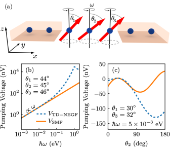
Equations (16) and (17) contain only the lowest order time and spatial derivatives of magnetization Freimuth2018 , so that comparing them to our nonperturbative results from TD-NEGF+LLG makes it possible to establish limits of validity of these equations. For this purpose, we employ a toy noncoplanar and noncollinear system consisting of three localized magnetic moments precessing with the same frequency , which is illustrated in Fig. 7(a) and it is akin to a system analyzed in Fig. 6 but with different precession cone angles , and . Similarly to studies combining classical micromagnetics with SMF formula Yamane2016 , the temporal dependence of these three localized magnetic moments is plugged into the discretized version of Eq. (16)
| (18) | |||||
Since Eqs. (15) and (18) do not allow us to compute charge current flowing into the leads, we plug from Eq. (18) into Eq. (15) to obtain the SMF voltage between the edges of the central region in Fig. 7(a). This is then compared to pumping voltage in an open circuit computed using charge current in Eq. (11) pumped into NM leads and two-terminal conductance obtained from the Landauer formula.
For small noncollinearity between three magnetic moments in Fig. 7(a)—, and —voltages and track each other, while following dependence, in Fig. 7(b) for all frequencies relevant for magnetization dynamics (the highest in the THz range, or eV, are encountered in the dynamics of antiferromagnets Jungfleisch2018 ). However, if we fix the precession frequency and change angles between neighboring magnetic moments, we find increasing deviation between and once the relative angles becomes in Fig. 7(c), which can reach factor of two difference at large angles.
IV DW motion driven by pulse current: Transient inertial displacement and spin and charge pumping
The pulse-current-driven DM motion is of particular relevance for racetrack memory applications Parkin2008 ; Parkin2015 where digital information is characterized by the orientation of the magnetic domain and data processing is carried out via current-induced DW motion. Thus, precise control of the position of the DW is required to achieve successful memory operation Thiaville2007 ; Thomas2010 ; Chauleau2010 ; Taniguchi2015 . Although the DW displacement is related to current pulse duration, it is in general not linear relation due to transient inertial displacement (or automotion) Thiaville2007 ; Thomas2010 ; Taniguchi2015 ; Pivano2017 ; Rhensius2010 appearing at current pulse onset and after pulse termination. Thus, too large transient inertial displacement will be detrimental for racetrack memory operation. The origin of transient inertial displacement is deformation of the DW leading to delayed response at the current onset and at the end of the current pulse, which then requires to tune the duration Thiaville2007 ; Thomas2010 ; Chauleau2010 ; Taniguchi2015 and the shape (i.e., its rise and fall time) Pivano2017 of the pulse. The experiments Thomas2010 ; Chauleau2010 ; Taniguchi2015 and classical micromagnetic simulations Thiaville2007 ; Chauleau2010 ; Pivano2017 typically employ short ns pulses, which generate higher DW velocities than longer s pulses due to easier depinning by an additional force on the DW during the pulse rise time or by a small mean distance between pinning centers.
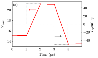
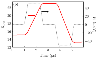
We apply a sequence of two successive voltage pulses of opposite polarity whose temporal characteristics is shown in Fig. 8 and whose magnitude is the same as the DC bias voltage used in Figs. 4, 5 and 6. We use rectangular [Fig. 8(a)] or trapezoidal [Fig. 8(b)] pulses of ps duration to understand basic physics and reduce computational expense. The first pulse drives DW forward (i.e., in the positive -direction in Fig. 1) and the second pulse drives the DW backward, so that in the absence of transient inertial displacement the DW center would return to its initial position in Fig. 8. The transient inertial displacement in Fig. 8, , is % of the forward displacement generated by the first pulse and surprisingly close to transient displacement observed in experiments where adiabatic STT drives the DW motion Taniguchi2015 . On the other hand, it is quite different from transient inertial displacement estimated Thiaville2007 via simple formula, , using 1D model of the DW ( is the angle variation of the DW, which is in the case of DW in Fig. 1). Thus, – nm predicted by this formula, for typical Gilbert damping – of magnetic nanowires, suggests transient displacement comparable or much larger than the bit size of the racetrack memory ( nm bit size is required for racetrack memory to be competitive to other memory devices Parkin2008 ; Parkin2015 ) which would be a significant impediment for its operation. Since it contradicts experiments where much smaller has been observed Taniguchi2015 , classical micromagnetic simulations aiming to reproduce such observation have suggested Taniguchi2015 that engineering of extrinsic pinning sites is necessary to obtain small .
Conversely, small we obtain in Fig. 8 for perfectly clean nanowires suggests the importance of inclusion of time-dependent quantum transport effects, such as spin and charge pumping generated while the DW experiences acceleration and deceleration due to injected pulse current. Figure 9 shows spin and charge currents in the NM leads, as well as locally between the sites of magnetic nanowire, which emerge upon applying a sequence of two rectangular pulses depicted in Fig. 9(a) and can be contrasted to the same information presented in Fig. 6 for the case of applied DC charge current. The charge currents in Figs. 9(a) and 9(c) do not follow the shape of the pulse due to additional charge current being pumped when the DW starts of stop moving. The same applies to spin current which in the absence of DW motion would quantify spin polarization Dolui2017 along the -axis after injected unpolarized charge current becomes polarized via propagation through magnetic nanowire depicted in Fig. 1. The spikes in spin currents at the instants of time where the pulse rises or decays would introduce additional terms in LLG dynamics which are absent in classical micromagnetics.
V Conclusions
In conclusion, we have developed a multiscale theoretical and computational framework which self-consistently couples time-dependent nonequilibrium quantum statistical description of conduction electrons with time-dependent classical description of localized magnetic moments. The TD-NEGF+LLG framework requires just time-dependent quantum and classical Hamiltonians, together with device geometry, as an input for computing the time evolution of the interacting electron–localized-magnetic-moments many-body system in numerically exact fashion. This can be contrasted with widely used classical micromagnetic simulations Xiao2005 ; Berkov2008 ; Stiles2007 ; Evans2014 ; Baumgartner2017 ; Lee2004a ; Stiles2007 ; Li2004 ; Li2004a ; Thiaville2005 ; Thiaville2007 ; Martinez2009 ; Boone2010 ; Chureemart2011 ; Iwasaki2013a ; Sampaio2013 ; Taniguchi2015 , where propagating conduction electrons appear only indirectly through phenomenological spin torque terms inserted by hand into the LLG equation; or with previous steady-state-NEGF+LLG attempts Ohe2006a ; Ohe2006b ; Salahuddin2006 ; Xie2017 ; Ellis2017 to couple quantum electrons to classical localized magnetic moments where fast electrons are assumed to instantaneously respond to slow dynamics of localized magnetic moments so that noncommutativity of the electronic quantum Hamiltonian at different times is neglected. Using DW motion driven by steady or pulse injected charge current as an example, we essentially demonstrate introduction (via TD-NEGF) of quantum spin pumping by the dynamics of localized magnetic moments and additional time-retarded damping characterized by a memory kernel Sayad2015 ; Hammar2016 into classical micromagnetics. In addition, we quantify nonperturbatively charge and spin currents pumped from time-dependent magnetic texture into the attached NM leads. They can be used as signatures of the dynamics of DWs, skyrmions and spin superfluids Kim2017b that can be detected by standard charge transport measurements. The same problem of charge pumping by time-dependent magnetic textures is also tackled by the SMF theory Barnes2007 ; Zhang2009b ; Kim2012b ; Berger1986 ; Volovik1987 ; Stern1992 ; Saslow2007 ; Duine2008 ; Tserkovnyak2008a ; Liu2011e ; Lucassen2011 ; Yamane2011 ; Hals2015 ; Yamane2016 . However, its analytical formula in Eq. (16) is perturbative in nature (i.e., it contains only the lowest order time and spatial derivatives of magnetization), and direct comparison with nonperturbative TD-NEGF+LLG framework shows [Fig. 7] that it fails when angles between neighboring localized magnetic moments exceed .
Acknowledgements.
We thank L. E. F. Foa Torres for instructive discussions. M. D. P. and P. P. were supported by ARO MURI Award No. W911NF-14-0247. B. S. P., U. B. and B. K. N. were supported by NSF Grant No. CHE 1566074. The supercomputing time was provided by XSEDE, which is supported by NSF Grant No. ACI-1548562.References
- (1) D. Ralph and M. Stiles, Spin transfer torques, J. Magn. Magn. Mater. 320, 1190 (2008).
- (2) J. Xiao, A. Zangwill, and M. D. Stiles, Macrospin models of spin transfer dynamics, Phys. Rev. B 72, 014446 (2005).
- (3) D. V. Berkov and J. Miltat, Spin-torque driven magnetization dynamics: Micromagnetic modeling, J. Magn. Magn. Mater. 320, 1238 (2008).
- (4) A. Yamaguchi, T. Ono, S. Nasu, K. Miyake, K. Mibu, and T. Shinjo, Real-space observation of current-driven domain wall motion in submicron magnetic wires, Phys. Rev. Lett. 92, 077205 (2004).
- (5) G. Tatara, H. Kohno, and J. Shibata, Microscopic approach to current-driven domain wall dynamics, Phys. Rep. 468, 213 (2008).
- (6) K.-J. Kim, Y. Yoshimura, and T. Ono, Current-driven magnetic domain wall motion and its real-time detection, Jap. J. Appl. Phys. 56, 0802A4 (2017).
- (7) K.-J. Lee, A. Deac, O. Redon, J.-P. Noziéres, and B. Dieny, Excitations of incoherent spin-waves due to spin-transfer torque, Nat. Mater. 3, 877 (2004).
- (8) M. Baumgartner et al., Spatially and time-resolved magnetization dynamics driven by spin-orbit torques, Nat. Nanotech. 12, 980 (2017).
- (9) N. Nagaosa and Y. Tokura, Topological properties and dynamics of magnetic skyrmions, Nat. Nanotech. 8, 899 (2013).
- (10) A. Fert, V. Cros, and J. Sampaio, Skyrmions on the track, Nat. Nanotech. 8, 152 (2013).
- (11) N. Locatelli, V. Cros, and J. Grollier, Spin-torque building blocks, Nat. Mater. 13, 11 (2014).
- (12) A. D. Kent and D. C. Worledge, A new spin on magnetic memories, Nat. Nanotech. 10, 187 (2015).
- (13) J. Grollier, D. Querlioz, and M. D. Stiles, Spintronic nanodevices for bioinspired computing, Proc. IEEE 104, 2024 (2016).
- (14) W. A. Borders, H. Akima, S. Fukami, S. Moriya, S. Kurihara, Y. Horio, S. Sato, and H. Ohno, Analogue spin–orbit torque device for artificial-neural-network-based associative memory operation, Appl. Phys. Expr. 10, 013007 (2017).
- (15) A. Manchon, I. M. Miron, T. Jungwirth, J. Sinova, J. Zelezný, A. Thiaville, K. Garello, and P. Gambardella, Current-induced spin-orbit torques in ferromagnetic and antiferromagnetic systems, https://arxiv.org/abs/1801.09636.
- (16) B. K. Nikolić, K. Dolui, M. Petrović, P. Plecháč, T. Markussen and K. Stokbro, First-principles quantum transport modeling of spin-transfer and spin-orbit torques in magnetic multilayers, https://arxiv.org/abs/1801.05793.
- (17) S. S. P. Parkin, M. Hayashi, and L. Thomas, Magnetic domain-wall racetrack memory, Science 320, 190 (2008).
- (18) S. Parkin and S.-H. Yang, Memory on the racetrack, Nat. Nanotech. 10, 195 (2015).
- (19) W. Koshibae, Y. Kaneko, J. Iwasaki, M. Kawasaki, Y. Tokura, and N. Nagaosa, Memory functions of magnetic skyrmions, Jap. J. Appl. Phys. 54, 053001 (2015).
- (20) R. F. L. Evans, W. J. Fan, P. Chureemart, T. A. Ostler, M. O. A. Ellis, and R. W. Chantrell, Atomistic spin model simulations of magnetic nanomaterials, J. Phys.: Condens. Matter 26, 103202 (2014).
- (21) M. D. Stiles, W. M. Saslow, M. J. Donahue, and A. Zangwill, Adiabatic domain wall motion and Landau-Lifshitz damping, Phys. Rev. B 75, 214423 (2007); N. Smith, Comment on “Adiabatic domain wall motion and Landau-Lifshitz damping”, Phys. Rev. B 78, 216401 (2008).
- (22) P. M. Haney, D. Waldron, R. A. Duine, A. S. Núñez, H. Guo, A. H. MacDonald, Current-induced order parameter dynamics: Microscopic theory aplied to Co/Cu/Co spin valves, Phys. Rev. B 76, 024404 (2007).
- (23) S. Wang, Y. Xu, and K. Xia, First-principles study of spin-transfer torques in layered systems with noncollinear magnetization, Phys. Rev. B 77, 184430 (2008).
- (24) Z. Yu, L. Zhang, and J. Wang, First-principles investigation of transient spin transfer torque in magnetic multilayer systems, Phys. Rev. B 96, 075412 (2017).
- (25) I. Theodonis, N. Kioussis, A. Kalitsov, M. Chshiev, and W. H. Butler, Anomalous bias dependence of spin torque in magnetic tunnel junctions, Phys. Rev. Lett. 97, 237205 (2006).
- (26) C. Heiliger and M. D. Stiles, Ab initio studies of the spin-transfer torque in magnetic tunnel junctions, Phys. Rev. Lett. 100, 186805 (2008).
- (27) M. Stamenova, R. Mohebbi, J. Seyed-Yazdi, I. Rungger, and S. Sanvito, First-principles spin-transfer torque in CuMnAsGaPCuMnAs junctions, Phys. Rev. B 95, 060403(R) (2017).
- (28) S. Zhang and Z. Li, Roles of nonequilibrium conduction electrons on the magnetization dynamics of ferromagnets, Phys. Rev. Lett. 93, 127204 (2004).
- (29) I. Garate, K. Gilmore, M. D. Stiles, and A. H. MacDonald, Nonadiabatic spin-transfer torque in real materials, Phys. Rev. B 79, 104416 (2009).
- (30) P. Baláž, V. K. Dugaev, and J. Barnaś, Spin-transfer torque in a thick Néel domain wall, Phys. Rev. B 85, 024416 (2012).
- (31) X. Waintal and M. Viret, Current-induced distortion of a magnetic domain wall, EPL (Europhysics Letters) 65, 427 (2004).
- (32) J. Xiao, A. Zangwill, and M. D. Stiles, Spin-transfer torque for continuously variable magnetization, Phys. Rev. B 73, 054428 (2006).
- (33) G. Tatara, H. Kohno, J. Shibata, Y. Lemaho, K.-J. Lee, Spin torque and force due to current for general spin textures, J. Phys. Soc. Japan 76, 054707 (2007).
- (34) Z. Yuan and P. J. Kelly, Spin-orbit-coupling induced torque in ballistic domain walls: Equivalence of charge-pumping and nonequilibrium magnetization formalisms, Phys. Rev. B 93, 224415 (2016).
- (35) Z. Li and S. Zhang, Domain-wall dynamics driven by adiabatic spin-transfer torques, Phys. Rev. B 70, 024417 (2004).
- (36) Z. Li and S. Zhang, Domain-Wall dynamics and spin-wave excitations with spin-transfer torques, Phys. Rev. Lett. 92, 207203 (2004).
- (37) A. Thiaville, Y. Nakatani, J. Miltat, and Y. Suzuki, Micromagnetic understanding of current-driven domain wall motion in patterned nanowires, EPL (Europhysics Letters) 69, 990 (2005).
- (38) A. Thiaville, Y. Nakatani, F. Piéchon, J. Miltat, and T. Ono, Transient domain wall displacement under spin-polarized current pulses, Eur. Phys. J. B 60, 15 (2007).
- (39) E. Martinez, L. Lopez-Diaz, O. Alejos, L. Torres, and M. Carpentieri, Domain-wall dynamics driven by short pulses along thin ferromagnetic strips: Micromagnetic simulations and analytical description, Phys. Rev. B 79, 094430 (2009).
- (40) C. T. Boone and I. N. Krivorotov, Magnetic domain wall pumping by spin transfer torque, Phys. Rev. Lett. 104, 167205 (2010).
- (41) P. Chureemart, R. F. L. Evans, and R. W. Chantrell, Dynamics of domain wall driven by spin-transfer torque, Phys. Rev. B 83, 184416 (2011).
- (42) J. Iwasaki, M. Mochizuki, and N. Nagaosa, Current-induced skyrmion dynamics in constricted geometries, Nat. Nanotech. 8, 742 (2013).
- (43) J. Sampaio, V. Cros, S. Rohart, A. Thiaville, and A. Fert, Nucleation, stability and current-induced motion of isolated magnetic skyrmions in nanostructure, Nat. Nanotech. 8, 839 (2013).
- (44) M. E. Knoester, J. Sinova, and R. A. Duine, Phenomenology of current-skyrmion interactions in thin films with perpendicular magnetic anisotropy, Phys. Rev. B 89, 064425 (2014).
- (45) K. M. D. Hals and A. Brataas, Spin-orbit torques and anisotropic magnetization damping in skyrmion crystals, Phys. Rev. B 89, 064426 (2014).
- (46) H.-B. Braun, Topological effects in nanomagnetism: From superparamagnetism to chiral quantum solitons, Adv. Phys. 61, 1 (2012).
- (47) C. A. Akosa, P. B. Ndiaye, and A. Manchon, Intrinsic nonadiabatic topological torque in magnetic skyrmions and vortices, Phys. Rev. B 95, 054434 (2017).
- (48) J. I. Ohe and B. Kramer, Dynamics of a domain wall and spin-wave excitations driven by a mesoscopic current, Phys. Rev. Lett. 96, 027204 (2006).
- (49) J. I. Ohe and B. Kramer, Current-induced spin fluctuation state in a mesoscopic magnetic wire, Phys. Rev. B 74, 201305(R) (2006).
- (50) S. Salahuddin and S. Datta, Self-consistent simulation of quantum transport and magnetization dynamics in spin-torque based devices, Appl. Phys. Lett. 89, 153504 (2006).
- (51) M. O. A. Ellis, M. Stamenova, and S. Sanvito, Multiscale modeling of current-induced switching in magnetic tunnel junctions using ab initio spin-transfer torques, Phys. Rev. B 96, 224410 (2017).
- (52) Y. Xie, J. Ma, S. Ganguly, A. W. Ghosh, From materials to systems: A multiscale analysis of nanomagnetic switching, J. Comput. Electron. 16, 1201 (2017).
- (53) C. A. Akosa, W.-S. Kim, A. Bisig, M. Kläui, K.-J. Lee, and A. Manchon, Role of spin diffusion in current-induced domain wall motion for disordered ferromagnets, Phys. Rev. B 91, 094411 (2015).
- (54) D. Claudio-Gonzalez, A. Thiaville, and J. Miltat, Domain wall dynamics under nonlocal spin-transfer torque, Phys. Rev. Lett. 108, 227208 (2012).
- (55) K.-J. Lee, M. D. Stiles, H.-W. Lee, J.-H. Moon, K.-W. Kim, and S.-W. Lee, Self-consistent calculation of spin transport and magnetization dynamics, Phys. Rep. 531, 89 (2013).
- (56) M. Sturma, C. Bellegarde, J.-C. Toussaint, and D. Gusakova, Simultaneous resolution of the micromagnetic and spin transport equations applied to current-induced domain wall dynamics, Phys. Rev. B 94, 104405 (2016).
- (57) G. Stefanucci and R. van Leeuwen, Nonequilibrium Many-Body Theory of Quantum Systems: A Modern Introduction (Cambridge University Press, Cambridge, 2013).
- (58) Y. Tserkovnyak, A. Brataas, G. E. W. Bauer, and B. I. Halperin, Nonlocal magnetization dynamics in ferromagnetic heterostructures, Rev. Mod. Phys. 77, 1375 (2005).
- (59) S.-H. Chen, C.-R. Chang, J. Q. Xiao, and B. K. Nikolić, Spin and charge pumping in magnetic tunnel junctions with precessing magnetization: A nonequilibrium Green function approach, Phys. Rev. B 79, 054424 (2009).
- (60) K. M. D. Hals, A. Brataas, and Y. Tserkovnyak, Scattering theory of charge-current induced magnetization dynamics, EPL (Europhysics Letters) 90, 47002 (2010).
- (61) F. Mahfouzi, J. Fabian, N. Nagaosa, and B. K. Nikolić, Charge pumping by magnetization dynamics in magnetic and semimagnetic tunnel junctions with interfacial Rashba or bulk extrinsic spin-orbit coupling, Phys. Rev. B 85, 054406 (2012).
- (62) K.-W. Kim, J.-H. Moon, K.-J. Lee, and H.-W. Lee, Prediction of giant spin motive force due to Rashba spin-orbit coupling, Phys. Rev. Lett. 108, 217202 (2012).
- (63) M. Sayad and M. Potthoff, Spin dynamics and relaxation in the classical-spin Kondo-impurity model beyond the Landau-Lifshitz-Gilbert equation, New J. Phys. 17, 113058 (2015).
- (64) H. Hammar and J. Fransson, Time-dependent spin and transport properties of a single-molecule magnet in a tunnel junction, Phys. Rev. B 94, 054311 (2016).
- (65) T. Bose and S. Trimper, Retardation effects in the Landau-Lifshitz-Gilbert equation, Phys. Rev. B 83, 134434 (2011).
- (66) D. Thonig, J. Henk, and O. Eriksson, Gilbert-like damping caused by time retardation in atomistic magnetization dynamics, Phys. Rev. B 92, 104403 (2015).
- (67) L. Thomas, M. Hayashi, X. Jiang, R. Moriya, C. Rettner and S. S. P. Parkin, Oscillatory dependence of current-driven magnetic domain wall motion on current pulse length, Nature 443, 197 (2006).
- (68) L. Thomas, M. Hayashi, X. Jiang, R. Moriya, C. Rettner, and S. S. P. Parkin, Resonant amplification of magnetic domain-wall motion by a train of current pulses, Science 315, 1553 (2007).
- (69) L. Thomas, R. Moriya, C. Rettner, S. S. P. Parkin, Dynamics of magnetic domain walls under their own inertia, Science 330, 1810 (2010).
- (70) J.-Y. Chauleau, R. Weil, A. Thiaville, and J. Miltat, Magnetic domain walls displacement: Automotion versus spin-transfer torque, Phys. Rev. B 82, 214414 (2010).
- (71) T. Taniguchi, K.-J. Kim, T. Tono, T. Moriyama, Y. Nakatani, and T. Ono, Precise control of magnetic domain wall displacement by a nanosecond current pulse in Co/Ni nanowires, Appl. Phys. Express 8, 073008 (2015).
- (72) A. Pivano and V. O. Dolocan, Systematic motion of magnetic domain walls in notched nanowires under ultrashort current pulses, Phys. Rev. B 96, 224431 (2017).
- (73) B. Gaury, J. Weston, M. Santin, M. Houzet, C. Groth, and X. Waintal, Numerical simulations of time-resolved quantum electronics, Phys. Rep. 534, 1 (2014).
- (74) F. Mahfouzi, B. K. Nikolić, and N. Kioussis, Antidamping spin-orbit torque driven by spin-flip reflection mechanism on the surface of a topological insulator: A time-dependent nonequilibrium Green function approach, Phys. Rev. B 93, 115419 (2016).
- (75) N. Bode, L. Arrachea, G. S. Lozano, T. S. Nunner, and F. von Oppen, Current-induced switching in transport through anisotropic magnetic molecules, Phys. Rev. B 85, 115440 (2012).
- (76) F. Mahfouzi and B. K. Nikolić, How to construct the proper gauge-invariant density matrix in steady-state nonequilibrium: Applications to spin-transfer and spin-orbit torques, SPIN 3, 1330002 (2013).
- (77) S. E. Barnes and S. Maekawa, Generalization of Faraday’s law to include nonconservative spin forces, Phys. Rev. Lett. 98, 246601 (2007).
- (78) Shufeng Zhang and Steven S.-L. Zhang, Generalization of the Landau-Lifshitz-Gilbert equation for conducting ferromagnets, Phys. Rev. Lett. 102, 086601 (2009).
- (79) K. Gilmore, Y. U. Idzerda and M. D. Stiles, Identification of the dominant precession-damping mechanism in Fe, Co, and Ni by first-principles calculations, Phys. Rev. Lett. 99, 027204 (2007).
- (80) A. Croy and U. Saalmann, Propagation scheme for nonequilibrium dynamics of electron transport in nanoscale devices, Phys. Rev. B 80, 245311 (2009).
- (81) B. S. Popescu and A. Croy, Efficient auxiliary-mode approach for time-dependent nanoelectronics, New J. Phys. 18, 093044 (2016).
- (82) B. K. Nikolić, L. P. Zârbo, and S. Souma, Imaging mesoscopic spin Hall flow: Spatial distribution of local spin currents and spin densities in and out of multiterminal spin-orbit coupled semiconductor nanostructures, Phys. Rev. B 73, 075303 (2006).
- (83) See Supplemental Material at https://wiki.physics.udel.edu/qttg/Publications for three movies, accompanying Figs. 3, 4 and 8, which show time evolution of localized magnetic moments in the course of DW motion induced by steady current or by voltage pulses of different shapes.
- (84) M. G. Vavilov, V. Ambegaokar, and I. L. Aleiner, Charge pumping and photovoltaic effect in open quantum dots, Phys. Rev. B 63, 195313 (2001).
- (85) M. Moskalets and M. Büttiker, Floquet scattering theory of quantum pumps, Phys. Rev. B 66, 205320 (2002).
- (86) L. E. F. Foa Torres, Mono-parametric quantum charge pumping: Interplay between spatial interference and photon-assisted tunneling, Phys. Rev. B 72, 245339 (2005).
- (87) U. Bajpai, B. S. Popescu, P. Plecháč, B. K. Nikolić, L. E. F. Foa Torres, H. Ishizuka, N. Nagaosa, Spatio-temporal dynamics of shift current quantum pumping by femtosecond light pulse, https://arxiv.org/abs/1803.04404.
- (88) A. Singh, S. Mukhopadhyay, and A. Ghosh, Tracking random walk of individual domain walls in cylindrical nanomagnets with resistance noise, Phys. Rev. Lett. 105, 067206 (2010).
- (89) P. Krzysteczko et al., Nanoscale thermoelectrical detection of magnetic domain wall propagation, Phys. Rev. B 95, 220410 (2017).
- (90) D. Wei, M. Obstbaum, M. Ribow, C. H. Back, and G. Woltersdorf, Spin Hall voltages from A.C. and D.C. spin currents, Nat. Commun. 5, 3768 (2014).
- (91) L. Berger, Possible existence of a Josephson effect in ferromagnets, Phys. Rev. B 33, 1572 (1986).
- (92) G. E. Volovik, Linear momentum in ferromagnets, J. Phys. C: Solid State Phys. 20, L83 (1987).
- (93) A. Stern, Berry’s phase, motive forces, and mesoscopic conductivity, Phys. Rev. Lett. 68, 1022 (1992).
- (94) W. M. Saslow, Spin pumping of current in non-uniform conducting magnets, Phys. Rev. B 76, 184434 (2007).
- (95) R. A. Duine, Spin pumping by a field-driven domain wall, Phys. Rev. B 77, 014409 (2008); R. A. Duine, Effects of nonadiabaticity on the voltage generated by a moving domain wall, Phys. Rev. B 79, 014407 (2009).
- (96) Y. Tserkovnyak and M. Mecklenburg, Electron transport driven by nonequilibrium magnetic textures, Phys. Rev. B 77, 134407 (2008).
- (97) Y. Liu, O. A. Tretiakov, and A. Abanov, Electrical signature of magnetic domain-wall dynamics, Phys. Rev. B 84, 052403 (2011).
- (98) M. E. Lucassen, G. C. F. L. Kruis, R. Lavrijsen, H. J. M. Swagten, B. Koopmans, and R. A. Duine, Spin motive forces due to magnetic vortices and domain walls, Phys. Rev. B 84, 014414 (2011).
- (99) Y. Yamane, J. Ieda, J. Ohe, S. E. Barnes, and S. Maekawa, Equation-of-motion approach of spin-motive force, J. Appl. Phys. 109, 07C735 (2011).
- (100) K. M. D. Hals and A. Brataas, Spin-motive forces and current-induced torques in ferromagnets, Phys. Rev. B 91, 214401 (2015).
- (101) S. A. Yang et al., Universal electromotive force induced by domain wall motion, Phys. Rev. Lett. 102, 067201 (2009).
- (102) P. N. Hai, S. Ohya, M. Tanaka, S. E. Barnes and S. Maekawa, Electromotive force and huge magnetoresistance in magnetic tunnel junctions, Nature 458, 489 (2009); D. C. Ralph, The Electromotive force of MnAs nanoparticles, Nature 474, E6 (2011).
- (103) K. Tanabe, D. Chiba, J. Ohe, S. Kasai, H. Kohno, S. E. Barnes, S. Maekawa, K. Kobayashi, and T. Ono, Spin-motive force due to a gyrating magnetic vortex, Nat. Commun. 3, 845 (2012).
- (104) F. Freimuth, S. Blügel, and Y. Mokrousov, Dynamical and current-induced Dzyaloshinskii-Moriya interaction: Role for damping, gyromagnetism, and current-induced torques in noncollinear magnets, https://arxiv.org/abs/1806.04782.
- (105) Y. Yamane, J. Ieda, and J. Sinova, Electric voltage generation by antiferromagnetic dynamics, Phys. Rev. B 93, 180408(R) (2016).
- (106) M. B. Jungfleisch, W. Zhang, and A. Hoffmann, Perspectives of antiferromagnetic spintronics, Phys. Lett. A 382, 865 (2018).
- (107) J. Rhensius, L. Heyne, D. Backes, S. Krzyk, L. J. Heyderman, L. Joly, F. Nolting, and M. Kläui, Imaging of domain wall inertia in permalloy half-ring nanowires by time-resolved photoemission electron microscopy, Phys. Rev. Lett. 104, 067201 (2010).
- (108) K. Dolui and B. K. Nikolić, Spin-memory loss due to spin-orbit coupling at ferromagnet/heavy-metal interfaces: Ab initio spin-density matrix approach, Phys. Rev. B 96, 220403(R) (2017).
- (109) S. K. Kim and Y. Tserkovnyak, Magnetic domain walls as hosts of spin superfluids and generators of skyrmions, Phys. Rev. Lett. 119, 047202 (2017).