Interference of Laguerre–Gaussian beams for reflection by dielectric slab
Abstract
We study reflection of TE Laguerre-Gaussian light beam by dielectric slab and show that the Goos-Hänchen and the Imbert-Federov shifts show resonant behavior following to the behavior of the reflection. Moreover the Imbert-Federov linear and the Goos-Hänchen angular shifts strongly depend on the orbital angular momentum . Due to destructive interference of two beams reflected from upper and down interfaces of the slab profile of the reflected light beam acquires structure which distinctively displays an amount of .
I Introduction
It is well established that a bounded beam upon reflection and transmission on a planar interface differs in propagation with plane waves due to diffraction corrections. This may manifest as beam shifts with respect to the geometric optics prediction when reflected or refracted. The more dominant shifts are the Goos-Hänchen (GH) shift in which the beam is displaced parallel to the plane of incidence Goos , and the Imbert-Federov (IF) shift in which the shift is perpendicular Imbert . Moreover, it has been shown that each of these two beam shifts can be separated into a spatial and an angular shift. The main distinction between spatial and angular shifts is the enhancement of the latter with the propagation of the beam Aiello .
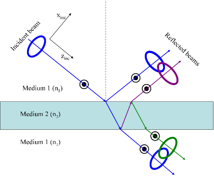
In the present letter we consider transmission and reflection of Laguerre-Gauss (LG) beams carrying orbital angular momentum (OAM) by dielectric slab. Specifically the effect of orbital angular momentum (OAM) on GH and IF shifts was considered for reflection of the LG beam from an interface Allen ; Fedoseyev2008 ; Bliokh2009 ; Merano2009 ; MeranoPRA ; Aiello2012 ; Merano2013 . Along with that reflection of Gaussian beams by dielectric slabs was considered to show negative shifts and resonant behavior of GH and IF shifts Riesz ; Li2003 ; Wang2005 ; Wen2017 . First reflection and transmission of LG beam in dielectric slab was considered by Li et al Li . The intensity distributions of the reflected and transmitted beams were presented which unambiguously show interference of two LG beams reflected from different interfaces and effects of vortices. In the present paper we develop these studies for reflection of LG beam by dielectric slab as sketched in Fig. 1. Owing to double reflection by two planes of the slab gives rise to an interference of two LG beams that in turn results in strong dependence of the GH and IF shifts on an amount of OAM. The most bright effect of such interference is a resonant behavior of GH and IF shifts as dependent on the angle of incidence and frequency of the incident beam.
II The method
The complex electric field amplitude of the reflected and transmitted beams is calculated using the angular spectrum method McGuirk and paraxial approximation. Following to Okuda and Sasada Okuda we do not consider cross-polarization effects Kohazi ; Bliokh2 because we choose the incident beam to have a small paraxial parameter . It is worthy to notify paper by Ou el where reflection of LG beam by dielectric surface was considered beyond the paraxial approximation by a full Teylor expansion Ou . Then, the TE or TM component of incident electric field has form
| (1) |
where is the LG-mode envelope function with the azimuthal and radial indices and respectively:
| (2) |
with , where ,
| (3) | |||
| (4) | |||
| (5) |
The angular spectral amplitude of the incident LG beam over the dielectric interface is given by Fourier transformation as
| (6) |
Multiplying Eq. (6) by the amplitude reflectance and the propagation phase factor Okuda , the amplitude of the reflected LG beam is obtained through inverse Fourier transformation
| (7) |
The central angular component of the incident paraxial beam is , the other components are mainly confined within
around the central component, where is the paraxial parameter Lax . For numerical integration we use and . Using transfer matrix method to calculate reflection and transmission coefficients through a slab we get
| (8) | |||
| (9) |
Here are Fresnel coefficients for TE or TM modes
| (10) | |||
| (11) | |||
| (12) | |||
| (13) |
with and .
III The results
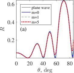
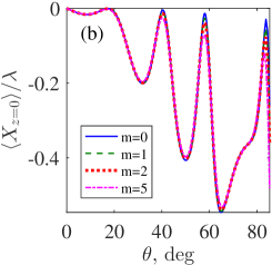
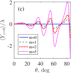
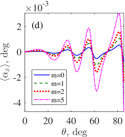
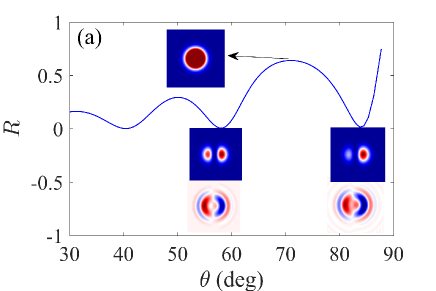
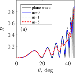
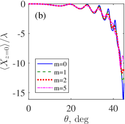
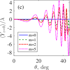
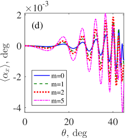
Fig. 2 (a) shows reflection of the LG beam with different OAM from dielectric slab versus the angle of incidence. One can see that the amount of OAM not strongly effect the reflection and the Goss-Hänchen shift. The obvious effect is related to disappearance of zeros of the reflection. However as Fig. 2 (c) and (d) show the Imbert-Fedorov shift and longitudinal angular shift are considerably depend on the OAM for reflection from the dielectric slab. The transversal angular shift is negligibly small of order deg and is not shown.
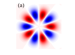
As seen from Fig. 1 for reflection of LG beam from the dielectric slab there is interference of, at least, two beams with destructive interference of beams with opposite OAMs. one can expect that total beam can have complicated structure in plane normal to the line of reflected beam. Fig. 3 show the structure of the incident LG beam, its real part at where a waist of the beam is minimal and at where the real part of function (II) demonstrates its spiralled structure because of difference in velocities of the beam at the center and the periphery.

In series of Figures in Fig. 4 we show evolution of the intensity and amplitude of the interfered LG beams with different OAM at those angles of incidence which correspond to minima and maxima of reflection.

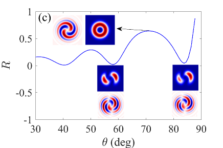
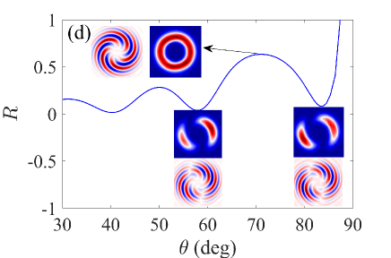
Comparison of Fig. 4 (b) to Fig. 3 (b) shows that the LG beam after reflection changes a chirality because of inversion of velocities. Moreover the structure of real part of the beam also changes significantly and distinctively reflects the amount of OAM in the LG beam.
Till now we considered the reflection of the LG beams from slab in air. In Fig. 5 we present results for GH and IF shifts for the opposite case of air slot in glass.
IV Discussion and summary
Bliokh et al Bliokh2009 predicted vortex-induced GH shift related to the angular IG angular shift for reflection of the LG beam from an interface separating two dielectric media. Similar phenomena take place for reflection from dielectric slab with two interfaces however the GH and IF shifts take resonant behavior with the angle of incidence as shown in Fig. 3. As one can expect an amount of the IF shifts strongly depend on the value of OAM , i.e., on a vorticity of LG beams. It is clear that sign of the IF shifts depends on the sign of . Second, for reflection from the dielectric slab the reflection and GH shift both weakly depend on OAM, while for reflection from air slot in dielectric medium the amount of OAM of LG beam affect resonant behavior of the reflection and GH shift as shown in Fig. 5 (a) and (b). Third, reflection of LB beam from slab and slot both gives rise to interference of neighbor LG beams that in turn results in structures of reflected light shown in Fig. 4.
We acknowledge discussions with Dmittrii Maksimov and Jayachandra Bingi. This work was supported RFBR grant 17-52-45072.
References
- (1) A. Aiello and J.P.Woerdman, ”Role of beam propagation in Goos–Hänchen and Imbert-Fedorov shifts,” Opt. Lett. 33, 1437–1439 (2008).
- (2) F. Goos and H. Hänchen,”Ein neuer und fundamentaler versuch zur Totalreflexion,” Ann. Phys. 436, 333–346 (1947).
- (3) C. Imbert, ”Calculation and experimental proof of the transverse shift induced by total internal reflection of a circular polarized light beam,” Phys. Rev. D 5, 787–796 (1972).
- (4) L. Allen, M.W. Beijersbergen, R.J.C. Spreeuw, and J.P. Woerdman, ”Orbital angular momentum of light and the transformation of Laguerre-Gaussian laser modes”, Phys. Rev. A45, 8115–8190 (1992).
- (5) V.G. Fedoseyev, ”Transformation of the orbital angular momentum at the reflection and transmission of a light beam on a plane interface”, J. Phys. A: Math. Gen 41, 505202 (2008).
- (6) K.Y. Bliokh, I.V. Shadrivov, and Yu.S. Kivshar,”Goos–Hänchen and Imbert–Fedorov shifts of polarized vortex beams”, Opt. Lett. 34, 389–391 (2009).
- (7) M. Merano, A. Aiello , M.P. van Exter and J.P. Woerdman, ”Observing angular deviations in the specular reflection of a light beam”, Nature Photonics 3, 337–340 (2009).
- (8) M. Merano, N. Hermosa, J. P. Woerdman, and A. Aiello, ”How orbital angular momentum affects beam shifts in optical reflection,” Phys. Rev. A 82, 023817 (2010).
- (9) A. Aiello, ”Goos–Hänchen and Imbert–Fedorov shifts: a novel perspective”, New J. Phys. 14, 013058 (2012).
- (10) G. Jayaswal, G. Mistura, and M. Merano, ”Weak measurement of the Goos–HÄchen shift”, Opt. Lett. 38, 1232 (2013).
- (11) R. P. Riesz and R. Simon, ”Reflection of a Gaussian beam from a dielectric slab,” Opt. Soc. Am. A 2, 1809–1817 (1985).
- (12) Chun-Fang Li, ”Negative Lateral Shift of a Light Beam Transmitted through a Dielectric Slab and Interaction of Boundary Effects”, Phys. Rev. Lett. 91, 133903 (2003).
- (13) Li-Gang Wang, Hong Chen, and Shi-Yao Zhu, ”Large negative Goos–Hänchen shift from a weakly absorbing dielectric slab,”, Opt. Lett. 30, 2936–2938 (2005).
- (14) Jisen Wen, Junxiang Zhang, Li-Gang Wang, and Shi-Yao Zhu, ”Goos–Hänchen shifts in an epsilon-near-zero slab”, J. Opt. Soc. Am. B 34, 2310–2316 (2017).
- (15) H. Li, F. Honary, Z. Wu, and L. Bai, ”Re?ection and transmission of Laguerre-Gaussian beams in a dielectric slab,” J. Quantitative Spectroscopy and Radiative Transfer 195, 35–43 (2017).
- (16) M. McGuirk and C. K. Carniglia, ”An angular spectrum representation approach to the Goos–Hänchen shift”, J. Opt. Soc. Am. 67, 103–107 (1975).
- (17) B.R. Horowitz and T. Tamir, ”Lateral Displacement of a Light Beam at a Dielectric Interface”, J. Opt. Soc. Am. 61, 586–594 (1971).
- (18) H. Okuda and H. Sasada, ”Significant deformations and propagation variations of Laguerre–Gaussian beams reflected and transmitted at a dielectric interface”, J. Opt. Soc. Am. 25, 881–890 (2008).
- (19) H. Okuda and H. Sasada, ”Huge transverse deformation in nonspecular reflection of a light beam possessing orbital angular momentum near critical incidence”, Opt. Express, 14, 8393–8402 (2006).
- (20) M. Lax, W.H. Louisell, and W.B. McKnight, ”From Maxwell to paraxial wave optics,” Phys.Rev. A11, 1365–1370 (1975).
- (21) A. Köházi-Kis, ”Cross-polarization effects of light beams at interfaces of isotropic media, Opt. Comm. 253, 28–37 (2005).
- (22) K.Y. Bliokh and Y.P. Bliokh, ”Polarization, transverse shifts,and angular momentum conservation laws in partial reflection and refraction of an electromagnetic wave packet,” Phys. Rev. E 75, 066609 (2007).
- (23) Jun Ou, Yuesong Jiang, Jiahua Zhang, and Yuntao He, ”Reflection of Laguerre–Gaussian beams carrying orbital angular momentum: a full Taylor expanded solution,” J. Opt. Soc. Am. A 30, 2561–2571 (2013).