Finite-Control-Set Model Predictive Control (FCS-MPC) for Islanded Hybrid Microgrids
Abstract
Microgrids consisting of multiple distributed energy resources (DERs) provide a promising solution to integrate renewable energies, e.g., solar photovoltaic (PV) systems. Hybrid AC/DC microgrids leverage the merits of both AC and DC power systems. In this paper, a control strategy for islanded multi-bus hybrid microgrids is proposed based on the Finite-Control-Set Model Predictive Control (FCS-MPC) technologies. The control loops are expedited by predicting the future states and determining the optimal control action before switching signals are sent. The proposed algorithm eliminates the needs of PI, PWM, and droop components, and offers 1) accurate PV maximum power point tracking (MPPT) and battery charging/discharging control, 2) DC and multiple AC bus voltage/frequency regulation, 3) a precise power sharing scheme among DERs without voltage or frequency deviation, and 4) a unified MPC design flow for hybrid microgrids. Multiple case studies are carried out, which verify the satisfactory performance of the proposed method.
I Introduction
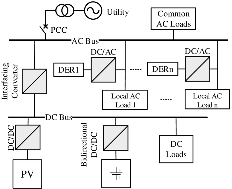
Deployments of renewable distributed energy resources (DERs) are expected to continuously increase in the near future, due largely to the declining capital investments, political incentives, and attractive natures [1, 2, 3]. Microgrid is a promising solution to integrate DERs with advanced control and energy management systems (EMS), which ensures the reliability while simultaneously offers a multitude of benefits to the utility [4, 5]. Introducing a DC network in a conventional AC microgrid, which forms a hybrid microgrid, is advantageous since it allows DC DERs (e.g., PV and battery storage) and DC loads (e.g., LED lighting and DC ventilation) to be interfaced directly with a significantly enhanced efficiency[6]. However, the coexistence of both DC and AC buses and DERs requires a sophisticated control system that is capable of managing the power flows effectively and ensuring the stable bus voltages/frequencies. Fig. 1 illustrates a typical hybrid microgrid, where PV and battery storage are integrated at the DC bus via DC/DC converters and DERs are connected at the AC bus via inverters. Each DER may also include a local bus and load. A bidirectional interfacing converter (IC) is installed between the DC and AC buses. The hybrid microgrid can operate in either grid-connected or islanded mode by switching the circuit breaker at the point of common coupling (PCC). This paper focuses on the control of islanded mode.
Control schemes for conventional microgrids have been extensively studied in the past decade, while those for hybrid microgrids are being actively explored during recent years. To ensure a reliable microgrid, controllers must be able to decouple the buses and the intermittent impacts from renewable DERs, and to control a precise power sharing among multiple DERs. A number of control strategies for hybrid microgrids have been proposed in the literature. Conventional Proportional-Integral (PI)-based controllers with Pulse Width Modulation (PWM) technique have been adopted in a wide range of circumstances, such as in Ref. [7, 8, 9, 10, 11]. These methods achieve various objectives such as control of multiple interlinking converters, decentralized control without communication links, AC and DC bus regulation, and power management. However, PI technique requires tuning of parameters, which is typically achieved by numerous trial-and-error processes, and needs re-tuning if system changes [12]. Moreover, PI controllers should be followed by external PWM modules. Ref. [13] introduces an adaptive-neural-network (ANN) control scheme for hybrid microgrids, which improves the dynamic performance and reacts adaptively to varying situations by using virtual flux direct power control. Nevertheless, ANN-based methods require massive historic data for the training process and the performance relies largely on the selection of training sets. In terms of power sharing among DERs, droop control and its variations are commonly adopted. A decentralized power management system is proposed in [14] to automatically adapt to operating conditions and maintain a power balance, while [9] presents a droop control strategy to realize power sharing at the common bus. Similarly, a hierarchical droop-control-based system is presented in [15]. Although droop control eliminates the communication links, it suffers from several major drawbacks: 1) voltage or frequency deviation, 2) poor transient performance, and 3) inability of accurate power sharing due to output impedance uncertainties [16].
As an attempt to address the aforementioned issues, this paper proposes a control scheme for multi-bus hybrid microgrids based on Finite-Control-Set Model Predictive Control (FCS-MPC). The proposed method eliminates the needs of PI, PWM, and droop control, and provides 1) accurate PV maximum power point tracking (MPPT) and battery power control, 2) voltage and frequency regulation with robust setpoint tracking for all buses, 3) a precise power sharing mechanism among the DERs without voltage or frequency deviation, and 4) a unified MPC design flow for hybrid microgrids. The FCS-MPC enables a faster control with satisfactory steady-state and dynamic performance, by predicting the future states of the control objectives and correcting the errors before switching signals are applied to converters/inverters. The rest of paper is organized as follows: Section II elaborates the system modeling and the proposed FCS-MPC for multi-bus hybrid microgrids, case studies based on PSCAD/EMTDC are presented in Section III, and Section IV concludes the paper.
II The Proposed FCS-MPC for Hybrid Microgrids
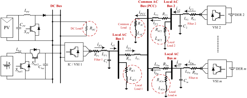
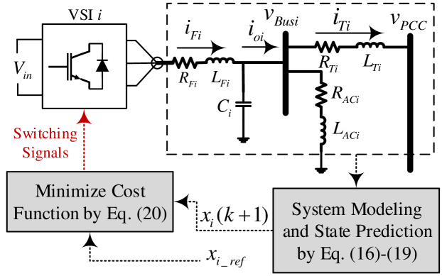
This section provides a unified process for designing FCS-MPC for multi-bus hybrid microgrids. Fig. 2 illustrates a typical configuration of an islanded hybrid microgrid with multiple DERs. On the DC side, the PV array and battery storage are connected at the DC bus via DC/DC converters, while on the AC side, each DER is interfaced at the common AC bus (PCC) via a voltage source inverter (VSI). VSI 1 works as an IC to interlink the DC and AC networks. There is a local bus with a load at the output of each VSI and a common bus with a load at PCC. The main philosophy of FCS-MPC is to predict the future behaviors of the system in a predefined time horizon based on the current/past states and possible control actuations. By minimizing a desired cost function, optimal control commands (i.e., switching signals) will be sent, which leads to a minimal error between the objectives and references. Note that the reference for each unit is determined by higher-level EMS, and this paper mainly focuses on primary control.
The FCS-MPC is designed based on the discrete-time state space of a power electronics stage, which is formulated as:
| (1) | ||||
| (2) |
The cost function, Eq. (3), which synthesizes the references, control actuations, and future states of the model, is then minimized subject to certain predefined constraints.
| (3) |
Optimization process is performed and optimal actuation will be updated as the horizon moves on each sampling time with new samples of measurements [17, 18]. The unified controller design process of each part is elaborated below.
II-A PV Controller Design
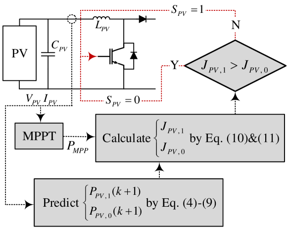
The PV controller aims at extracting the maximum power of the PV array in varying irradiance and temperature. Firstly, a MPPT algorithm (Incremental Conductance [19]) is employed to determine the real-time maximum power reference (). Based on the state space of DC/DC converter (boost), the next-sample-time value of the PV current () and voltage () can be derived by Eq. (4) and (5) if the next switch command () is “ON”, and by Eq. (6) and (7) if is “OFF”. denotes the sampling period.
| (4) | ||||
| (5) | ||||
| (6) | ||||
| (7) |
Thereby, the prediction of next PV power is calculated by:
| (8) | ||||
| (9) |
The cost functions for the PV controller are:
| (10) | ||||
| (11) |
By comparing Eq. (10) and (11), the switching signal that results in a minimal cost will be selected and sent to the converter. This process is presented in Fig. 3. Note that the size of PV does not affect the design process.
II-B Battery Controller Design
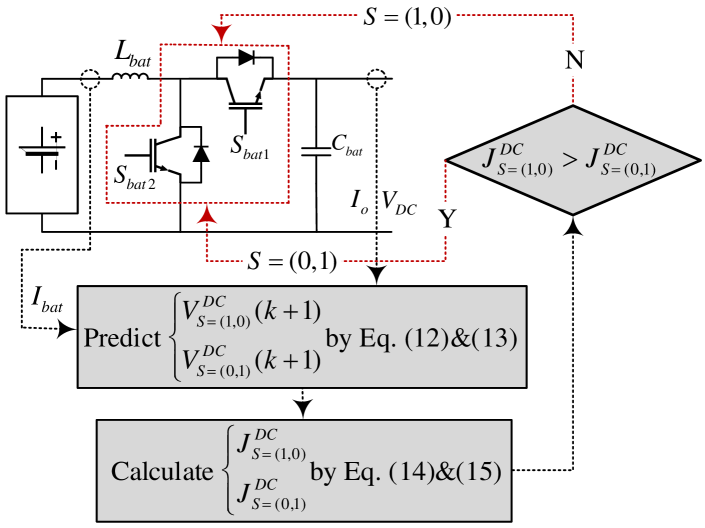
In the islanded mode of operation, the battery is used to regulate the DC bus while compensating for the power balance between generation and demand. The output voltage of the bidirectional converter, which is also the DC bus voltage, can be predicted by Eq. (12) and (13) when the switching signals equal and , respectively.
| (12) | ||||
| (13) |
Consequently, the cost functions can be defined by:
| (14) | ||||
| (15) |
Depending on the value of each cost function, optimal switching signals that minimize the cost will be delivered to the two switches of the bidirectional converter (Fig. 4).
II-C VSI Controller Design with Power Sharing Mechanism
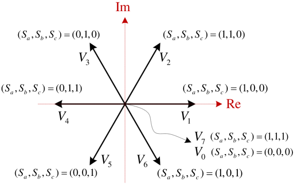
In an islanded multi-DER microgrid system, the voltage and frequency of AC buses are regulated by VSI controllers, which also provide a precise power sharing mechanism among the DERs for the common loads at PCC. The controller design process for each VSI is elaborated below. Each VSI is a conventional three-phase two-level inverter with three legs and two switches in each leg. Therefore, there will be eight possible switching combinations, which yields eight voltage vectors () for the VSI output:
| (16) |
where is the DC input voltage of each VSI. Switching signals for the upper three switches (, , ) are given based on the Space Vector Modulation (SVM) technique (Fig. 5), while the lower ones are triggered by (). Therefore, for a microgrid with VSIs (Fig. 2), the state prediction for VSI is derived as:
| (17) |
where
| (18) |
denotes the voltage of local AC bus and is the load impedance at PCC. The PCC bus voltage becomes:
| (19) |
Therefore, the optimal space vector that minimizes the following cost function will be selected:
| (20) |
where is the reference for and is the weighting factor. The power sharing mechanism is enabled by introducing the second term in with a group of power sharing ratios () to control the output current ratio among the VSIs. For instance, in a system with two VSIs (=2), by setting , the output power of VSI 1 will be half of VSI 2. Fig. 6 depicts this control process.
III Case Studies
To verify the proposed control strategies, a hybrid microgrid with the same configuration as Fig. 2 with two VSIs (=2) is modeled and the proposed FCS-MPC is implemented by Fortran in the PSCAD/EMTDC software package. Multiple case studies are carried out to validate the performance.
Case 1
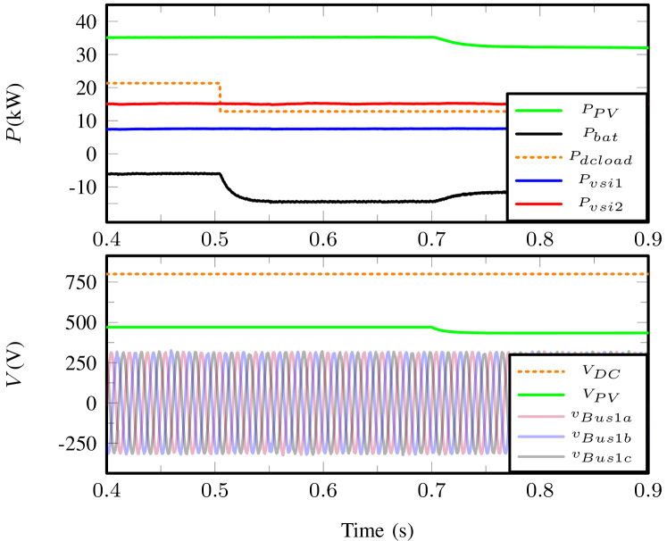
This case aims at verifying the proposed scheme for controlling the DC side powers and DC/AC bus voltages. The power sharing ratio is set to . As the results presented in Fig. 7, at 0.5 s, the DC load at the DC bus decreases from 21.5 kW to 13 kW (). Since the PV array is operating in MPPT mode and the power of VSI 1 is controlled by the MPC, the 8.5 kW excess power in the DC network will be absorbed by the battery. As a result, the battery charging power () increases from 6 kW to 14.5 kW in the negative direction. Note that negative power flow indicates charging the battery [20]. At 0.7 s, the irradiance of PV array declines. Consequently, PV voltage () drops and PV power () decreases from 35 kW to 32 kW. The battery power changes from 14.5 kW to 11.5 kW to compensate for the irradiance fluctuation, which ensures a reliable DC load power. The output powers of VSI 1 and 2 remain at 7.5 kW and 15 kW (), respectively. It is worth noting that transitions of all these changes are finished within 50 ms, which demonstrates a fast response speed of the proposed scheme. Moreover, the voltages of DC and AC buses are not affected during the transients.
Case 2
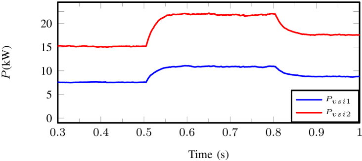
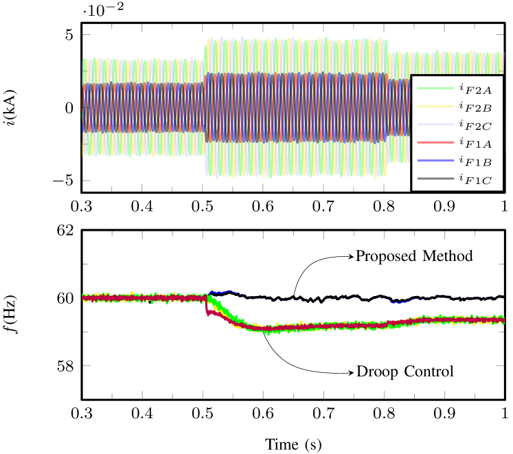
The second case study investigates the performance of power sharing mechanism. Since the microgrid is in islanded mode, the PCC common load is shared by VSI 1 and 2, which are initially 7.5 kW and 15 kW with (assuming no local loads). As is presented in Fig. 8, at 0.5 s, the common load at PCC increases by 10.5 kW. The powers of VSI 1 and 2 increase by 3.5 kW and 7 kW, respectively, which results in a 11 kW output for VSI 1 and a 22 kW output for VSI 2. Similarly, at 0.8 s, the common load decreases by 6.6 kW, resulting in 8.8 kW for VSI 1 and 17.6 kW for VSI 2. Note that is always 2 as controlled by . Fig. 9 shows the output currents of the two VSIs and the frequencies of three AC buses (Bus 1, Bus 2, and PCC in Fig. 2) during these transitions. The current amplitude of VSI 1 is always half of VSI 2. The bus frequencies controlled by the proposed method 60 Hz with negligible fluctuations (0.2 %) during the transitions, while extra case studies using droop control show significant bus frequency deviations during load changes.
Case 3
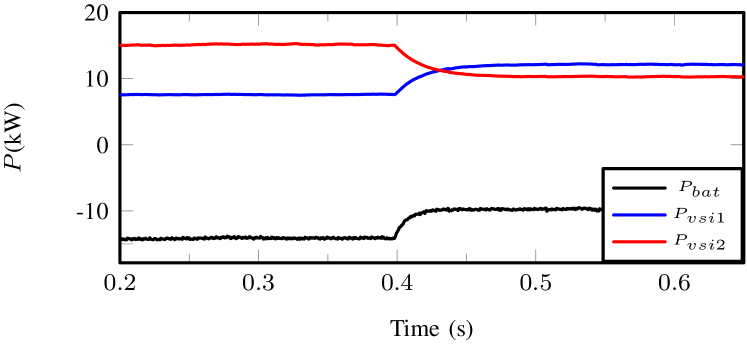
This case aims at verifying the flexibility of the proposed method in adjusting power sharing ratio (). Initially, is set to 1/2, which yields 7.5 kW and 15 kW for VSI 1 and VSI 2, respectively. At 0.4 s, increases to 8/7. The output of VSI 1 ( in Fig.10) increases to 12 kW whereas the output of VSI 2 () decreases to 10.5 kW, which complies with the change of and maintains a reliable power (22.5 kW) at PCC. Moreover, this verifies how the battery power on the DC side responds to the change.
IV Conclusions
This paper introduces a control strategy for multi-bus hybrid microgrids based on FCS-MPC, which eliminates the needs of PI controller, PWM module, and droop control with an improved steady-state and dynamic performance. The proposed scheme predicts the future states of the hybrid microgrid and decides the optimal control actuations before switching signals are sent. It achieves accurate PV MPPT and battery charging/discharging control, DC and AC bus voltage/frequency setpoint tracking, and precise power sharing among DERs at the PCC without voltage or frequency deviation, and offers a unified MPC design approach for hybrid microgrids. Case studies are performed to verify the proposed control strategy.
References
- [1] Z. Yi and A. H. Etemadi, “Line-to-line fault detection for photovoltaic arrays based on multiresolution signal decomposition and two-stage support vector machine,” IEEE Trans. Ind. Electron., vol. 64, no. 11, pp. 8546–8556, Nov 2017.
- [2] Z. Yi and A. H. Etemadi, “Fault detection for photovoltaic systems based on multi-resolution signal decomposition and fuzzy inference systems,” IEEE Trans. Smart Grid, vol. 8, no. 3, pp. 1274–1283, May 2017.
- [3] Z. Yi and A. H. Etemadi, “A novel detection algorithm for line-to-line faults in photovoltaic (PV) arrays based on support vector machine (SVM),” in 2016 IEEE Power and Energy Society General Meeting (PESGM), July 2016, pp. 1–4.
- [4] D. Shi, X. Chen, Z. Wang, X. Zhang, Z. Yu, X. Wang, and D. Bian, “A distributed cooperative control framework for synchronized reconnection of a multi-bus microgrid,” IEEE Trans. Smart Grid, vol. PP, no. 99, pp. 1–1, 2017.
- [5] C. Yuan, M. A. Haj-ahmed, and M. S. Illindala, “Protection strategies for medium-voltage direct-current microgrid at a remote area mine site,” IEEE Trans. Ind. Appl., vol. 51, no. 4, pp. 2846–2853, July 2015.
- [6] A. Gupta, S. Doolla, and K. Chatterjee, “Hybrid AC-DC microgrid: Systematic evaluation of control strategies,” IEEE Trans. Smart Grid, vol. PP, no. 99, pp. 1–1, 2017.
- [7] S. Peyghami, H. Mokhtari, and F. Blaabjerg, “Autonomous operation of a hybrid AC/DC microgrid with multiple interlinking converters,” IEEE Trans. Smart Grid, vol. PP, no. 99, pp. 1–1, 2017.
- [8] P. Wang, C. Jin, D. Zhu, Y. Tang, P. C. Loh, and F. H. Choo, “Distributed control for autonomous operation of a three-port AC/DC/DS hybrid microgrid,” IEEE Trans. Ind. Electron., vol. 62, no. 2, pp. 1279–1290, Feb 2015.
- [9] Y. Xia, W. Wei, M. Yu, X. Wang, and Y. Peng, “Power management for a hybrid AC/DC microgrid with multiple subgrids,” IEEE Trans. Power Electron., vol. PP, no. 99, pp. 1–1, 2017.
- [10] T. Ma, M. H. Cintuglu, and O. A. Mohammed, “Control of a hybrid AC/DC microgrid involving energy storage and pulsed loads,” IEEE Trans. Ind. Appl., vol. 53, no. 1, pp. 567–575, Jan 2017.
- [11] Z. Yi, W. Dong, and A. H. Etemadi, “A unified control and power management scheme for PV-battery-based hybrid microgrids for both grid-connected and islanded modes,” IEEE Trans. Smart Grid, vol. PP, no. 99, pp. 1–1, 2017.
- [12] A. J. Babqi and A. H. Etemadi, “MPC-based microgrid control with supplementary fault current limitation and smooth transition mechanisms,” IET Generation, Transmission Distribution, vol. 11, no. 9, pp. 2164–2172, 2017.
- [13] N. Chettibi, A. Mellit, G. Sulligoi, and A. M. Pavan, “Adaptive neural network-based control of a hybrid AC/DC microgrid,” IEEE Trans. Smart Grid, vol. PP, no. 99, pp. 1–13, 2016.
- [14] H. Mahmood, D. Michaelson, and J. Jiang, “Decentralized power management of a PV/battery hybrid unit in a droop-controlled islanded microgrid,” IEEE Trans. Power Electron., vol. 30, no. 12, pp. 7215–7229, Dec 2015.
- [15] X. Lu, J. M. Guerrero, K. Sun, J. C. Vasquez, R. Teodorescu, and L. Huang, “Hierarchical control of parallel AC-DC converter interfaces for hybrid microgrids,” IEEE Trans. Smart Grid, vol. 5, no. 2, pp. 683–692, March 2014.
- [16] M. Yazdanian and A. Mehrizi-Sani, “Distributed control techniques in microgrids,” IEEE Trans. Smart Grid, vol. 5, no. 6, pp. 2901–2909, Nov 2014.
- [17] M. B. Shadmand, R. S. Balog, and H. Abu-Rub, “Model predictive control of pv sources in a smart DC distribution system: Maximum power point tracking and droop control,” IEEE Trans. Energy Convers., vol. 29, no. 4, pp. 913–921, Dec 2014.
- [18] A. J. Babqi, Z. Yi and A. H. Etemadi,“Centralized finite control set model predictive control for multiple distributed generator small-scale microgrids,” 2017 North American Power Symposium (NAPS), Morgantown, WV, 2017, pp. 1-5.
- [19] X. Zhang, “Control strategy of cascaded H-bridge multilevel inverter with PV system as separate dc source,” M.S. thesis, Royal Institute of Technology, Stockholm, Sweden, 2011.
- [20] Z. Yi, “Solar Photovoltaic (PV) Distributed Generation Systems-Control and Protection”. Ph.D. dissertation, The George Washington University, Washington, DC, 2017.