Influence of a chemical reaction on viscous fingering:
Effect of the injection flow rate
Abstract
The hydrodynamic viscous fingering instability can be influenced by a simple viscosity changing chemical reaction of type , when a solution of reactant is injected into a solution of and a product of different viscosity is formed. We investigate here numerically such reactive viscous fingering in the case of a reaction decreasing the viscosity to define the optimal conditions on the chemical and hydrodynamic parameters for controlling fingering. In particular, we analyze the influence of the injection flow rate or equivalently of the Péclet number () of the problem on the efficiency of the chemical control of fingering. We show that the viscosity decreasing reaction has an increased stabilizing effect when is decreased. On the contrary, fingering is more intense and the system more unstable when is increased. The related reactive fingering patterns cover then respectively a smaller (larger) area than in the non-reactive equivalent. Depending on the value of the flow rate, a given chemical reaction may thus either enhance or suppress a fingering instability. This stabilization and destabilization at low and high are shown to be related to the -dependent characteristics of a minimum in the viscosity profile that develops around the miscible interface thanks to the effect of the chemical reaction.
I Introduction
A hydrodynamic viscous fingering (VF) instability can deform the interface between two different fluids when a high mobility fluid of lower viscosity displaces a more viscous and hence less mobile one in a porous medium Saffman and Taylor (1958); Saffman (1986); Tan and Homsy (1986); Homsy (1987); Tan and Homsy (1988). In numerous industrial and environmental problems such as enhanced oil recovery, sequestration, combustion, hydrology, soil remediation, etc. Orr and Taber (1984); Lunn and Kueper (1999); Fu et al. (2013); Farajzadeh et al. (2015); Ritsema et al. (1998), this fingering instability can interplay with chemical reactions. In the past few decades, viscous fingering has been analyzed in reactive systems on both miscible and immiscible interfaces (Hornof and Baig, 1995; Jahodab and Hornofa, 2000; Nagatsu and Ueda, 2001, 2003; Nagatsu et al., 2009a; De Wit and Homsy, 1999a, b; Fernandez and Homsy, 2003; Podgorski et al., 2007; Nagatsu et al., 2007; Gérard and De Wit, 2009; Nagatsu et al., 2009b; Hejazi et al., 2010; Hejazi and Azaiez, 2010a, b; Nagatsu and De Wit, 2011; Nagatsu et al., 2011; Riolfo et al., 2012; Riolfo, 2013; Alhumade and Azaiez, 2013; Nagatsu, 2010). If the reaction does not modifies the viscosity in-situ, the chemical species are passively advected by the flow and the fingering properties of the interface remain similar to those of the nonreactive system Hornof and Baig (1995); Jahodab and Hornofa (2000); Nagatsu and Ueda (2001, 2003); Nagatsu et al. (2009a). The flow in the fingering patterns can on the other hand change the spatio-temporal distribution of the reactants and influence the yield of the reaction. Active influence of chemistry on fingering can be obtained as soon as the chemical reaction taking place around the interface between the two fluids modifies their physical properties and, in particular, their viscosity Wit (2016). The reaction then influences the stability as well as the spatio-temporal dynamics of the flow. In turn, the hydrodynamic flow affects mixing and thus the amount and spatial distribution of chemical species and a highly nonlinear feedback is established between chemistry and hydrodynamics.
For cases where reactions actively change the viscosity in-situ, numerical simulations have first shown on the basis of a bistable chemical reaction scheme that the properties of miscible VF are modified when the reaction changes the viscosity across the reactive miscible interface De Wit and Homsy (1999a, b). The bistable nature of chemical kinetics is then responsible for a new phenomenon of droplet formation isolating regions of high or low viscosity within connected domains of the other steady state. In other studies, the active influence of types of chemical reaction on miscible viscous fingering has been studied both experimentally Podgorski et al. (2007); Nagatsu et al. (2007); Nagatsu et al. (2009b); Nagatsu et al. (2011); Riolfo et al. (2012); Riolfo (2013) and theoretically Gérard and De Wit (2009); Hejazi et al. (2010); Hejazi and Azaiez (2010a, b); Nagatsu and De Wit (2011); Riolfo et al. (2012); Alhumade and Azaiez (2013). Podgorski et al. (2007) have in particular studied experimentally chemically-driven fingering at the miscible reactive interface between two aqueous solutions of same viscosity when a reaction between a cationic surfactant and an organic salt produces an elastic more viscous worm-like micellar fluid. Various fingering regimes have been identified depending on concentrations, fluid characteristics and injection flow rate (or equivalently Péclet number, defined as the ratio of the convective to diffusive transport rates).
In some experiments by Nagatsu et al., a less-viscous acidic or basic aqueous solution was injected into a more-viscous polymeric solution, the viscosity of which depends on pH Nagatsu et al. (2007); Nagatsu et al. (2009b); Nagatsu et al. (2011). It is observed that, when the viscosity is increased (decreased) by the reaction, fingers are widened (narrowed), which is mainly due to suppressed (enhanced) shielding effects. Interestingly, opposite results have been observed at moderate reaction rates for systems with a viscosity decrease Nagatsu et al. (2009b) and increase Nagatsu et al. (2011). In the case where the non reactive displacement is stable (more viscous solution displacing a less viscous once), it has even been shown experimentally that the reaction is able to trigger VF Riolfo et al. (2012). Depending whether the reaction increases or decreases viscosity, a different fingering pattern is then obtained.
The experimental study of Nagatsu et al. Nagatsu et al. (2007) showed that at ‘large’ injection rate, or equivalently high Péclet number (), an instantaneous chemical reaction can have opposite effects on miscible VF when a less viscous (acidic or basic) solution is injected radially into a more viscous (e.g. polymeric solution) one in a Hele-Shaw cell depending whether the reaction locally increases or decreases the viscosity. In the viscosity increase case, the VF pattern is “denser” in the sense that it covers a more compact area in the Hele-Shaw cell than the non-reactive pattern. On the contrary, a VF pattern covering a smaller area (also qualified as “less dense pattern”) was reported in the viscosity decrease reactive case. Recently, new experiments have been carried out focusing on the influence of the injection rate on viscosity increasing and decreasing reactive systems Riolfo (2013); Nagatsu and Masumo (2015). Interestingly, it was found that, at lower Pe, the trends are opposite than at high i.e. for viscosity decreasing reactions, the system can be stabilized at low injection flow rates. These experiments Nagatsu et al. (2007); Riolfo (2013); Nagatsu and Masumo (2015) thus clearly show that, in the presence of a viscosity decreasing reaction, the reactive VF patterns can be controlled by varying the Péclet number. Moreover, when the reaction induced viscosity decrease is large enough, a suppression of the VF instability can be obtained at small . In numerical studies, the explicit influence of the injection rate on reactive VF has however not been addressed explicitly.
In this context, our objective is here to analyze numerically the influence on the VF instability of changes in the injection flow rate i.e. changes in the number of the problem when a simple chemical reaction decreases the viscosity in situ. To this end, we integrate numerically the reaction-diffusion-convection (RDC) equations of reactive VF in porous media and analyze the properties of the fingering patterns for different values of . We show that a viscosity-decreasing reaction enhances stabilization or destabilization of the interface at respectively low and high , with regard to the non-reactive system. This is related to the possibility at low for chemistry to build up a minimum in the viscosity profile that blocks the further progression of fingering and stabilizes the system. On the contrary, at high , chemistry does not have time to act to decrease the viscosity and the classical enhanced destabilization when the flow rate is increased is then observed.
These results highlights the optimum conditions on flow conditions to obtain stabilization by reactions of VF. This is of practical importance as it paves the way to a possible chemical control of fingering instabilities appearing in many practical situations ranging from geophysical to environmental problems.
This paper is organized as follows. The problem description and the related RDC model are given in Sec. II. In Sec. II.2, the numerical method used to integrate the model is discussed. The characteristics of VF patterns and in particular the influence of the Péclet number are studied in Sec. III. The non-reactive and reactive cases are given in III.1 and III.2, respectively. A quantitative analysis and parametric study are carried out in Secs. III.3 and IV. At the end, conclusions and outlook are given in Sec. V.
II Problem description and governing equations
Consider a homogeneous two-dimensional porous medium or horizontal thin Hele-Shaw cell of length and width with constant permeability in which a miscible solution of reactant with viscosity is injected from left to right into a solution of reactant with viscosity at a constant speed along the -direction (Fig.1). We assume that the initial concentrations of and are both equal to . The initial position of the miscible interface is .
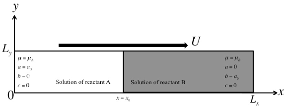
Upon contact between the two solutions, a simple chemical reaction takes place in the miscible interface zone where and meet by diffusion, react, and yield the product of viscosity . The objective is to analyze numerically how the dynamic decrease of viscosity driven by the reaction can influence the VF instability and in particular what is the influence of the injection speed on this effect.
To analyze the problem, the system is considered as incompressible and neutrally buoyant. The dynamics is modeled using Darcy’s law for the velocity field along with three reaction-diffusion-convection (RDC) equations for the concentrations:
| (1) | ||||
| (2) | ||||
| (3) | ||||
| (4) | ||||
| (5) |
where , , and denote the concentrations of the reactants and and of the product , respectively, is the kinetic constant, is the pressure, , and are the diffusivities of the reactants and and the product , respectively, is the two-dimensional flow velocity and is the constant permeability. The viscosities of the solution when only one species is present in concentration are defined as , and , respectively in the presence of the reactants , or of the product . Following previous theoretical work on viscous fingering (Tan and Homsy, 1986; De Wit and Homsy, 1999b, a; Mishra et al., 2007; Gérard and De Wit, 2009; Hejazi et al., 2010; Hejazi and Azaiez, 2010a, b; Nagatsu and De Wit, 2011; Riolfo, 2013; Alhumade and Azaiez, 2013), we assume the viscosity as an exponential function of the concentrations of , and as
| (6) |
where and are the log-mobility ratios defined as
| (7) |
For the non-reactive VF case or the equivalent specific reactive case when the product has the same viscosity as one of the reactant (i.e. ), the system is unstable when the lower viscosity solution of A displaces the more viscous solution of B i.e. when or . Let us analyze how this stability is changed when both and the injection speed are varied.
II.1 Non-dimensional Equations
To specifically let the injection speed appear in the dimensionless problem under the form of a Péclet number, the reference scales for length, velocity, time, concentration, viscosity, diffusivity and pressure are taken as , , , , , and , respectively. For simplicity, equations are written in a reference frame moving with speed by transforming variables as and with being the unit vector along direction. The dimensionless form of (1)–(6) can then be written as
| (8) | ||||
| (9) | ||||
| (10) | ||||
| (11) | ||||
| (12) | ||||
| (13) |
where is the dimensionless Damköhler number defined as the ratio of the hydrodynamic time scale to the chemical time scale . The Péclet number is the ratio of the convective time to the diffusive time while and are the diffusion coefficient ratios. Taking the curl of the momentum equation and defining the stream function as and , we get
| (14) | |||||
| (15) | |||||
| (16) | |||||
| (17) |
where the subscripts and represent the respective derivatives. The last term in (15)–(17) corresponds to the reaction rate :
| (18) |
Comparing the present RDC model (14)–(17) with those previously studied in the literature Tan and Homsy (1988); Gérard and De Wit (2009); Hejazi et al. (2010); Nagatsu and De Wit (2011); Pramanik and Mishra (2015), we note that: (i) when we recover the classical model for non-reactive viscous fingering similar to the one studied by Tan and Homsy Tan and Homsy (1988); Pramanik and Mishra (2015); (ii) when , and we obtain the model of reactive VF for solutions of A and B of same viscosity as analyzed numerically by Gérard and De Wit (2009); (iii) when , we get back to the reactive VF model with , and of different viscosity but species diffusing all at the same rate as studied by Hejazi et al. (2010) and Nagatsu and De Wit (2011).
As the dynamics of the reactive zone is independent of boundary conditions as long as the unstable fingered front does not confront its periodic extension Tan and Homsy (1988), we use periodic boundary conditions in both directions. The initial conditions for the stream function and product concentration are taken as and , for all , respectively. For the initial concentrations of the reactant and solutions, we use a step front between on the left and on the right of with a random noise of amplitude of order added in the front to trigger the instability. The dimensionless system size is , where is the aspect ratio. Equations (14)–(17) together with the initial and boundary conditions form an initial-boundary value problem with six dimensionless control parameters—namely, , , , , and . To decrease the wide range of possibilities, we fix here to focus on the effect of the reaction (variable and for a given ) and flow speed (variable ) on the fingering instability.
II.2 Numerical Method
To solve (14)–(17), we use a pseudo-spectral numerical scheme based on the discrete Fourier transform library FFTW 3.3.4 (Tan and Homsy, 1988; Fornberg, 1998; De Wit and Homsy, 1999a, b; Gérard and De Wit, 2009). In order to avoid any interaction between the unstable fingered front and its periodic extension, we choose a domain with a large aspect ratio. The physical and computational domain size () are and , respectively. The time step of numerical integration is chosen as . To validate our code, we have successfully reproduced previous nonlinear simulation results of non-reactive (Tan and Homsy, 1988; Pramanik and Mishra, 2015) and reactive (Gérard and De Wit, 2009; Hejazi et al., 2010; Nagatsu and De Wit, 2011) systems.
III Results
III.1 Non-reactive system
It is already known that, in absence of any reaction effect ( or Hejazi et al. (2010); Nagatsu and De Wit (2011)), increasing the injection speed (i.e. increasing in our dimensionless formulation of the problem) increases the destabilization of the interface by VF when (Tan and Homsy, 1988; Homsy, 1987; Pramanik and Mishra, 2015). As a reference case, this observation is shown in Fig. 2 which illustrates the concentration of reactants ( and ) for and , respectively, at four different times. As increases, fingering becomes more intense and the wavelength of the pattern decreases as the interface becomes more unstable. It is also observed that, at low Pe, the deformed interface tends to flatten as time evolves thanks to transverse diffusion.
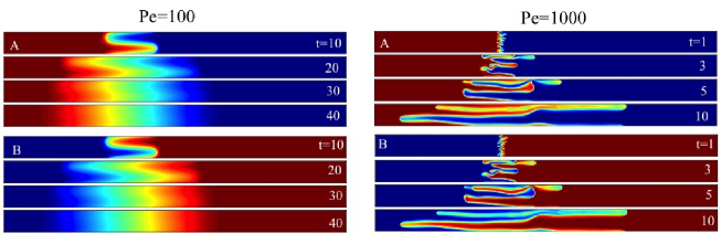


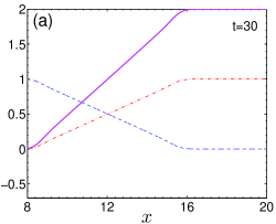
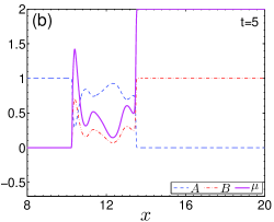
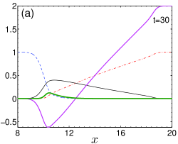
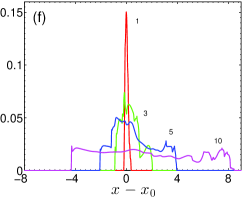
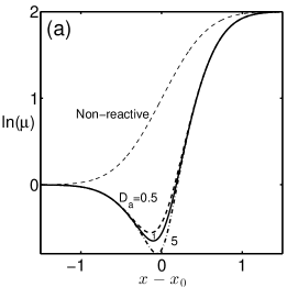
Figure 3 compares the one dimensional profiles of the concentrations of and , and the logarithm of viscosity at a fixed transverse location for at time and at , respectively. As a reference, the white line is shown in the corresponding two-dimensional map of on the top of the panels. While the concentrations and viscosity profiles at large show bumps characteristic of the fingering instability, these profiles are quasi linear between the end-point values at small indicating a more stable interface. This stabilizing effect at low Pe is in agreement with previous results Tan and Homsy (1986, 1988); Pramanik and Mishra (2015).
III.2 Reactive system
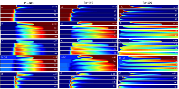
Let us now analyze the effect of on reactive VF when an reaction produces the product of lower viscosity (negative value of ) such that the viscosity of the system develops in time a minimum around the reactive front.
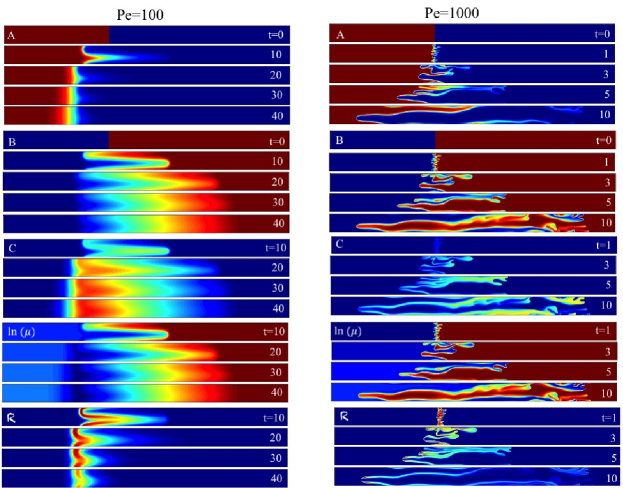
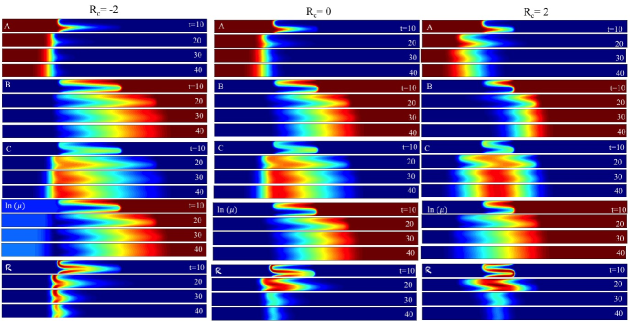
Figure 4 shows the concentrations, , and reaction rate at , and for two values of Péclet numbers (first column) and (second column). Two opposite behaviours are obtained at low and high Pe: at , fingering is more intense than in the non reactive case with coarsening, and more repetitive shielding and tip splitting Nagatsu and De Wit (2011). The fingered zone extends on a larger spatial extent than in the non reactive case (Fig.2) suggesting that the reaction has here a destabilizing effect. A comparison of the transverse averaged viscosity profile in the non reactive (Fig.3b) and reactive (Fig.5b) cases shows that, at , the decrease in viscosity induced by the reaction leads to a sharper viscosity jump which can explain the increased destabilisation. As a consequence, fingering extends both in the - and -rich regions with the reaction rate being localised at the fingered frontier between the two reactants. On the contrary, at (Fig.4, first column), a minimum in viscosity develops in the course of time where the less viscous separates the two reactants and (Fig.5a). The reaction rate correspondingly decreases in time and remains strongly localised at a given location. The time scales are also longer as more time is needed to cover the same distance. Interestingly, fingering is weak and remains longer in the boundary zone where the less viscous displaces the more viscous then in the stable part of the non-monotonic profile where A pushes the less viscous . This means that, in experiments where often a dye is used to visualize the fingering pattern, the instability would quickly become unnoticeable if the dye is diluted in the injected A reactant Riolfo (2013).
A comparison of the spatio-temporal distribution of in Fig.2 (non reactive) and 4 (reactive) leads thus to the conclusion that, at high , reactive fingering is more intense with more ramified fingers that cover a larger area in the presence of reaction. On the contrary, at low , fingering is stabilized by the reaction. The effect of the reaction decreasing the viscosity has thus an opposite effect on the flow at high and low Pe, as observed experimentally Riolfo (2013); Nagatsu et al. (2007).


III.3 Quantitative analysis
In order to understand the opposite dynamics at low and high Pe, and to quantify the influence of varying on reactive VF, we compute the one-dimensional transversely averaged profiles of given quantities, as
| (19) |
where can be, for instance, concentration, viscosity, etc. In absence of fingering (), these profiles are equivalent to the one-dimensional reaction diffusion profiles. For the simulations of Fig. 4, the temporal evolution of some of these transversely averaged profiles is shown in Fig. 6.
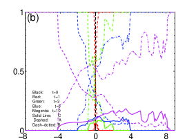
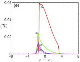
In the convective flow regime, the fingering pattern starts to develop around the reactive interface as soon as solutions and react and produce a less-viscous product , see Figs. 6(a) and 6(b). As the system evolves in time, we see that increasing amounts of and are consumed and that the total production of the product increases. The corresponding reaction rate , shown in Fig. 6(e), decreases in time when and are consumed and are progressively separated by . Fig. 6(c) shows the development of viscosity as time evolves. At low , a viscosity minimum develops in time at the back of the reaction front where the product concentration is maximum which can also be seen from Figs. 4(c) and 4(d). Owing to the viscosity minimum, the interface between and is stabilized, which can clearly be observed in Fig. 4(a) as the interface tends to flatten. On the contrary, the interface between and where the less viscous pushes the more viscous indicates the presence of VF. Nevertheless, transverse diffusion finally dominates VF, and the interface between and eventually stabilizes again [see Fig. 4(a–e)].
Let us now analyze quantitatively fingering patterns at larger . We have noticed in Fig. 4(f–j) that reactive VF is destabilizing at high in contrast to a stabilizing trend at low . Figures 6(b,d,f) show that, at high , when VF is present, the transversely averaged concentration profiles feature bumps indicating the presence of forward and backward fingering. In contrast to fingering at the back, forward fingering shows merging and tip-splitting, see Fig. 4(f–j). Similar to the concentration, the log-viscosity, Fig. 6(d), and reaction rate profiles, Fig. 6(f), show similar features. The center of mass of these profiles is shifted towards the right of the reaction front indicating the presence of more elongated fingering in the -rich region. While, at low , the viscosity minimum formed at the back (or left) of the reaction front gives rise to stabilization, it is completely absent at high causing VF to expand significantly around the reaction zone.
IV Parametric Study
We have seen that fingering is stabilized at lower when the viscosity decreases thanks to a chemical reaction. To gain more insight into this stabilization effect, a parametric study is next carried out at several low values to understand the effect of varying the Damköhler number and the viscosity of the product by changing the log-mobility ratio .
IV.1 Effect of mobility ratio at
The effect of changing the log-mobility ratio is shown on Fig. 7. We consider the three values , , . We remind that, when (=2 here), the consumption of is balanced by the production of , hence the dynamics of the reactive case is equivalent to that of the non reactive system. When , the viscosity decreases by the reaction but the viscosity profile remains monotonic in space. On the contrary, if , a minimum in viscosity develops in time. For , the cases , and represent thus the (i) non-reactive VF, (ii) reactive VF with monotonic viscosity, and (iii) reactive VF with a viscosity minimum, respectively.
By comparing concentrations of , and for various time steps in these three cases, we see that, when , the viscosity minimum has the following effects: (i) The interface between and stabilizes rapidly and the mixing of reactant decreases as compared to the other two cases, (ii) as time evolves, the mixing region between and increases and stops fingering in time, displacing more by the product . The reactive VF is stabilized at low by the viscosity minimum compared to the reactive VF case with monotonic viscosity or the non-reactive VF.
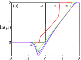
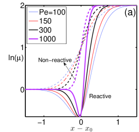
.
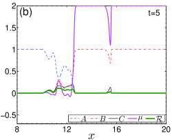
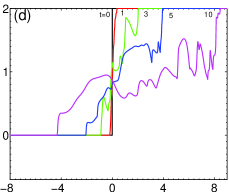
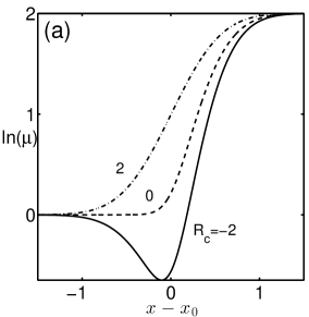
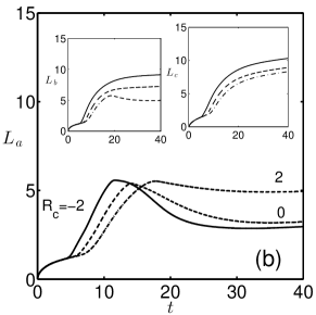
The origin of this stabilization can be explained through the long time asymptotic one-dimensional reaction diffusion (RD) profiles of , as shown in Fig. 8(a). If , the reaction diffusion viscosity front moves in time from the higher viscosity region of to the lower viscosity region of , see Fig. 6(a). Due to the presence of lower viscosity region containing , the profile of develops a minimum in the -rich region. While the gradients are decreasing with on the left of the reaction front [], those on the right [] are increasing. Owing to this, when , the miscible interface between and is more stable as is the case when a higher viscosity fluid displaces a lower viscosity one. As a consequence, the mixing length decreases rapidly as time evolves and finally reaches a steady value which is the lowest among all cases, as shown in the main panel of Fig. 8(b).
In contrast to the interface between and , the interface between and is more unstable when because is then the steepest, see Fig. 8(a). This can also be noticed in the evolution of the mixing length of and in Fig. 8(b). The instability at the interface between and starts earlier and the mixing length and increase more in time as decreases. As time evolves (far from the onset), due to transverse diffusion, and reach a steady value which increases with decreasing . The displacement of is thus larger when in comparison to and (non-reactive). From Figs. 4–8, we can thus conclude that, when , the front between and stabilizes, the mixing between and is increased and the displacement of is larger.
IV.2 Effect of Péclet number
In the previous section, we have seen that the onset time decreases i.e. the system is initially more unstable as decreases. We now fix and analyze the effect on fingering of changing keeping it nevertheless at small values. Specifically, concentrations, and the reaction rate are shown for (first column), (second column) and (third column) in Fig. 9. We see that the system becomes more unstable when increasing . This can be understood by inspecting the one-dimensional RD profiles shown in Fig. 10(a). The non-reactive displacement (dashed lines) is more unstable at higher because the gradient of viscosity is correspondingly sharper. Similarly, viscosity gradients in the reactive RD systems (solid lines) are larger when increases as diffusion is then less efficient to smooth the viscosity profile. Consequently, the RDC system also becomes more unstable with increasing , as shown in Fig. 9 and on the evolution of the mixing lengths, see Fig. 10(b) where we see that the onset time of the fingering instability decreases with increasing . The smaller , the quicker the mixing lengths tend to a steady state value at low whereas at large the mixing lengths are increasing instantaneously irrespective of the viscosity minimum at the interface.
IV.3 Effect of Damköhler number,
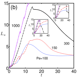
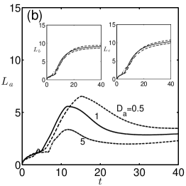
To study the effect of varying the Damköhler number on the stabilization of fingering instability thanks to reactions decreasing the viscosity, Figure 11 depicts the concentrations, and the reaction rate at successive times for three values of . We see that, when increasing (i.e. the reaction occurs faster), the viscosity minimum develops more quickly (see also Fig. 12(a)), the amount of product formed at a given time increases, and the reaction rate decays faster because the reactants and are increasingly separated by the product . As a consequence, when increases, the miscible interface between and stabilizes faster and the steady value of decreases. In parallel, the interface between and becomes uniform in time, and the corresponding values of and saturates (see Fig. 12(b)). The system is thus globally more stable when is larger.
We conclude thus from this parametric study that the displacement tends to stabilize (destabilize) at lower (high ) for (), and larger (smaller ). The optimal conditions to avoid fingering can thus be achieved when the viscosity is decreasing by a fast chemical reaction provided the rate of injection of displacing fluid is kept as low as possible to allow the viscosity minimum to build up.
V Conclusion and Outlook
We have here analysed the influence of the injection flow rate on reactive VF driven by a simple type chemical reaction decreasing the viscosity in situ. To do so, we have numerically integrated Darcy’s law for the evolution of the flow velocity and RDC equations for the concentrations coupled by a viscosity profile depending dynamically on the concentration of the chemical species. The injection flow rate has been varied by changing the values of the dimensionless parameter . Nonlinear simulations have been performed to characterise the properties of reactive VF when a solution of a reactant displaces a solution of to produce the less viscous product at the miscible reactive interface. At lower , the VF instability is less intense in both reactive and non reactive cases because the viscosity gradients are smoothed out by diffusion. The reactive VF pattern covers nevertheless a larger area i.e. is spatially denser than the non-reactive pattern. These observations are in good agreement with experiments Riolfo (2013); Nagatsu et al. (2007). Similarly to the non-reactive case, at higher , VF is enhanced in reactive systems when the viscosity minimum does not have time to build up. Less-dense fingering patterns and more mixing are then observed. In other words, the fingering patterns at high cover a smaller area than at low . In terms of displacement efficiency, the presence of a viscosity minimum at lower is found to optimize a homogeneous and regular displacement with less convective mixing.
Our study provides a mathematical framework to control VF in many geophysical processes e.g. reactive pollutant displacement, sequestration and EOR. Recently, it has been shown that fingering instabilities in the application of EOR can be controlled by introducing a viscosity minimum in the zone of contact between the two fluids via the formation of foam between the injected gas and displaced oil Farajzadeh et al. (2015). In this context, the present study (i) provides a convection between viscosity minimum and stabilization, (ii) introduces a way to control VF by controlling the injection rate, (iii) shows that, at low injection rate, the reactive VF improves the sweep efficiency in comparison to the non reactive conditions.
Acknowledgment
We thank Y. Nagatsu, F. Brau, F. Haudin and M. Mishra for fruitful discussions. P.S. acknowledges financial support from IIT Madras for a New Faculty Initiation Grant, and a New Faculty Seed Grant. A.D. acknowledges PRODEX for financial support.
References
- Saffman and Taylor (1958) P. G. Saffman and G. I. Taylor, “The penetration of a fluid into a porous medium or Hele-Shaw cell containing a more viscous liquid,” Proc. R. Soc. Lond. A 245, 312 (1958).
- Saffman (1986) P. G. Saffman, “The penetration of a fluid into a porous medium or Hele-Shaw cell containing a more viscous liquid,” J. Fluid Mech. 173, 73 (1986).
- Tan and Homsy (1986) C. T. Tan and G. M. Homsy, “Stability of miscible displacements in porous media: Rectilinear flow,” Phys. Fluids 29, 3549 (1986).
- Homsy (1987) G. M. Homsy, “Viscous fingering in porous media,” Annu. Rev. Fluid Mech. 19, 271 (1987).
- Tan and Homsy (1988) C. T. Tan and G. M. Homsy, “Simulation of nonlinear viscous fingering in miscible displacement,” Phys. Fluids 31, 1330 (1988).
- Orr and Taber (1984) F. M. Orr and J. J. Taber, “Use of carbon dioxide in enhanced oil recovery,” Science 224, 563 (1984).
- Lunn and Kueper (1999) S. R. Lunn and B. H. Kueper, “Manipulation of density and viscosity for the optimization of DNAPL recovery by alcohol flooding,” J. Contam. Hydrol. 38, 427 (1999).
- Fu et al. (2013) X. Fu, L. Cueto-Felgueroso, and R. Juanes, “Pattern formation and coarsening dynamics in three-dimensional convective mixing in porous media,” Phil. Trans. R. Soc. 371 (2013).
- Farajzadeh et al. (2015) R. Farajzadeh, A. Eftekhari, H. Hajibeygi, J. van der Meer, S. Vincent-Bonnieu, and W. Rossen, in SPE Reservoir Simulation Symposium, Houston, Texas, USA, 23–25 February 2015 (Society of Petroleum Engineers, Texas, USA, 2015), pp. SPE–173193–MS.
- Ritsema et al. (1998) C. J. Ritsema, L. W. Dekker, J. L. Nieber, and T. S. Steenhuis, “Modeling and field evidence of finger formation and finger recurrence in a water repellent sandy soil,” Water Resour. Res. 34, 555 (1998).
- Hornof and Baig (1995) V. Hornof and F. U. Baig, “Influence of interfacial reaction and mobility ratio on the displacement in a hele-shaw cell,” Exp. Fluids 18, 448 (1995).
- Jahodab and Hornofa (2000) M. Jahodab and V. Hornofa, “Concentration profiles of reactant in a viscous finger formed during the interfacially reactive immiscible displacements in porous media,” Powder Technology 110, 253 (2000).
- Nagatsu and Ueda (2001) Y. Nagatsu and T. Ueda, “Effects of reactant concentrations on reactive miscible viscous fingering,” AIChE J. 47, 1711 (2001).
- Nagatsu and Ueda (2003) Y. Nagatsu and T. Ueda, “Effects of finger-growth velocity on reactive miscible viscous fingering,” AIChE J. 49, 789 (2003).
- Nagatsu et al. (2009a) Y. Nagatsu, T. Ogawa, Y. Kato, and Y. Tada, “Investigation of reacting flow fields in miscible viscous fingering by a novel experimental method,” AIChE J. 55, 563 (2009a).
- De Wit and Homsy (1999a) A. De Wit and G. M. Homsy, “Viscous fingering in reaction-diffusion systems,” J. Chem. Phys. 110, 8663 (1999a).
- De Wit and Homsy (1999b) A. De Wit and G. M. Homsy, “Nonlinear interactions of chemical reactions and viscous fingering in porous media,” Phys. Fluids 11, 949 (1999b).
- Fernandez and Homsy (2003) J. Fernandez and G. M. Homsy, “Viscous fingering with chemical reaction: effect of in-situ production of surfactants,” J. Fluid Mech. 480, 267 (2003).
- Podgorski et al. (2007) T. Podgorski, M. C. Sostarecz, S. Zorman, and A. Belmonte, “Fingering instabilities of a reactive micellar interface,” Phys. Rev. E 76, 016202 (2007).
- Nagatsu et al. (2007) Y. Nagatsu, K. Matsuda, Y. Kato, and Y. Tada, “Experimental study on miscible viscous fingering involving viscosity changes induced by variations in chemical species concentrations due to chemical reactions,” J. Fluid Mech. 571, 475 (2007).
- Gérard and De Wit (2009) T. Gérard and A. De Wit, “Miscible viscous fingering induced by a simple chemical reaction,” Phys. Rev. E 79, 016308 (2009).
- Nagatsu et al. (2009b) Y. Nagatsu, Y. Kondo, Y. Kato, and Y. Tada, “Effects of moderate damköhler number on miscible viscous fingering involving viscosity decrease due to a chemical reaction,” J. Fluid Mech 625, 97 (2009b).
- Hejazi et al. (2010) S. H. Hejazi, P. M. J. Trevelyan, J. Azaiez, and A. De Wit, “Viscous fingering of a miscible reactive interface: a linear stability analysis,” J. Fluid Mech. 652, 501 (2010).
- Hejazi and Azaiez (2010a) S. H. Hejazi and J. Azaiez, “Non-linear interactions of dynamic interfaces in porous media,” Chem. Eng. Sci. 65, 938 (2010a).
- Hejazi and Azaiez (2010b) S. H. Hejazi and J. Azaiez, “Hydrodynamic instability in the transport of miscible reactive slices through porous media,” Phys. Rev. E 81, 056321 (2010b).
- Nagatsu and De Wit (2011) Y. Nagatsu and A. De Wit, “Viscous fingering of a miscible reactive interface for an infinitely fast chemical reaction: Nonlinear simulations,” Phys. Fluids 23, 043103 (2011).
- Nagatsu et al. (2011) Y. Nagatsu, Y. Kondo, Y. Kato, and Y. Tada, “Miscible viscous fingering involving viscosity increase by a chemical reaction with moderate damköhler number,” Phys. Fluids 23, 014109 (2011).
- Riolfo et al. (2012) L. A. Riolfo, Y. Nagatsu, S. Iwata, R. Maes, P. M. J. Trevelyan, and A. De Wit, “Experimental evidence of reaction-driven miscible viscous fingering,” Phys. Rev. E 85, 015304 (2012).
- Riolfo (2013) L. Riolfo, Ph.D. thesis, Université libre de Bruxelles, Brussels (2013).
- Alhumade and Azaiez (2013) H. Alhumade and J. Azaiez, “Stability analysis of reversible reactive flow displacements in porous media,” Chem. Eng. Sci 101, 46 (2013).
- Nagatsu (2010) Y. Nagatsu, “Viscous fingering phenomena with chemical reactions,” Chem. Eng. Sci 65, 938 (2010).
- Wit (2016) A. D. Wit, “Chemo-hydrodynamic patterns in porous media,” Phil. Trans. Roy. Soc. A 374, 20150419 (2016).
- Nagatsu and Masumo (2015) Y. Nagatsu and T. Masumo, “personal communication,” – (2015).
- Mishra et al. (2007) M. Mishra, M. Martin, and A. De Wit, “Miscible viscous fingering with linear adsorption on the porous matrix,” Phys. Fluids 19, 073101 (2007).
- Pramanik and Mishra (2015) S. Pramanik and M. Mishra, “Effect of pećlet number on miscible rectilinear displacement in a hele-shaw cell,” Phys. Rev. E 91, 033006 (2015).
- Fornberg (1998) B. Fornberg, A Practical Guide to Pseudospectral Methods, Cambridge Monographs on Applied and Computational Mathematics (Cambridge University Press, 1998).