The Design for a Nanoscale Single-Photon Spin Splitter
Abstract
We propose using the effective spin-orbit interaction of light in Bragg-modulated cylindrical waveguides for the efficient separation of spin-up and spin-down photons emitted by a single photon emitter. Due to the spin and directional dependence of photonic stopbands in the waveguides, spin-up (down) photon propagation in the negative (positive) direction along the waveguide axis is blocked while the same photon freely propagates in the opposite direction.
Introduction. The development of nanophotonic devices brings an emergent research field of chiral quantum optics (CQO) LodahlNature17 in microscopic waveguides. When light is confined strongly in the transverse direction, its electromagnetic field oscillates along both transverse and longitudinal directions, resulting in a rotating electric field oriented perpendicular to its propagation direction and forming the transverse spin AielloNatPho15 ; BliokhPhysRep15 ; BliokhScience15 . The transverse spin is locked to momentum because its component flips sign with the inversion of propagation direction. When an emitter is embedded inside the waveguide, the light absorption and emission depend on the local distribution of the momentum-locked transverse spin, resulting in the CQO LuxmoorePRL13 ; JungePRL13 .
The transverse spin is an exemplification of a more general concept of spin-orbit interaction (SOI) of light, which arises due to the vectorial nature of the light field encountering wavelength-scale structures BliokhNatPho15 . Besides the transverse spin, the SOI of light results in phenomena such as the spin-Hall effect of light OnodaPRL14 ; BliokhPRL06 ; HostenScience08 ; AielloOptLett08 ; BliokhNatPho08 ; GorodetskiPRL12 ; BliokhJOpt13 and spin-to-orbital angular momentum conversion DogariuOptExp06 ; ZhaoPRL07 ; BliokhOptExp11 . Currently, many CQO designs rely heavily on chiral atom coupling JungePRL13 ; MitschNatPho14 ; ShomroniScience14 , making them hard to implement in integrated optical circuits IOCbook . To circumvent this constraint, here we realize a CQO design serving as a fully optical single-photon spin splitter by exploiting the SOI of light in cylindrical waveguides LearyPRA09 ; LearyPRA14 ; VitulloPRL17 without introducing any light-matter interaction. To achieve this, we need to combine effects from the SOI of light and the band gap structure of a photonic crystal.
When light is passing through a periodically modulated dielectric structure, the electric field tends to concentrate around the high refractive index regions JoannopoulosBook08 ; and a finite amount of energy would be required to change the electric field to the reverse distribution. Therefore, for a certain range of frequency there will be no propagating mode, i.e. the appearance of a photonic band gap JoannopoulosBook08 . Recent developments in fabrication have allowed embedding an ultra-long Bragg modulation (up to meter) in a waveguide GagneOptExp14 . Hence, a question will arise as to how the photonic band gap structure under the influence of transverse confinement is modified by the SOI of light. In this letter, we will try to answer this question by analyzing the SOI in the presence of a weak Bragg modulation in a cylindrical waveguide. We present a systematic method in dealing with transversely confined periodic structures by making clear the distinction between the Floquet exponent (i.e. the Bloch wave vector) KomlenkoBook05 ; FloquetTheory and the variable separation constant MyintBook07 , clarifying some misunderstandings found in the literature CarreteroOptExp06 ; PereyraHindawi17 . The SOI will lead to splitting of the propagation constants between and components in the helicity basis LearyPRA09 ; LearyPRA14 ; VitulloPRL17 . As a result, the photonic band gap will split accordingly and lead to spin-locked propagation modes protected by the photonic band gap structure, forming the foundation of our design of a single-photon spin splitter.
We will first introduce a general scheme for the dispersion calculation of Bragg mirrors under the influence of transverse confinements, and after that, the effect of SOI correction on the dispersion and band gap structures.
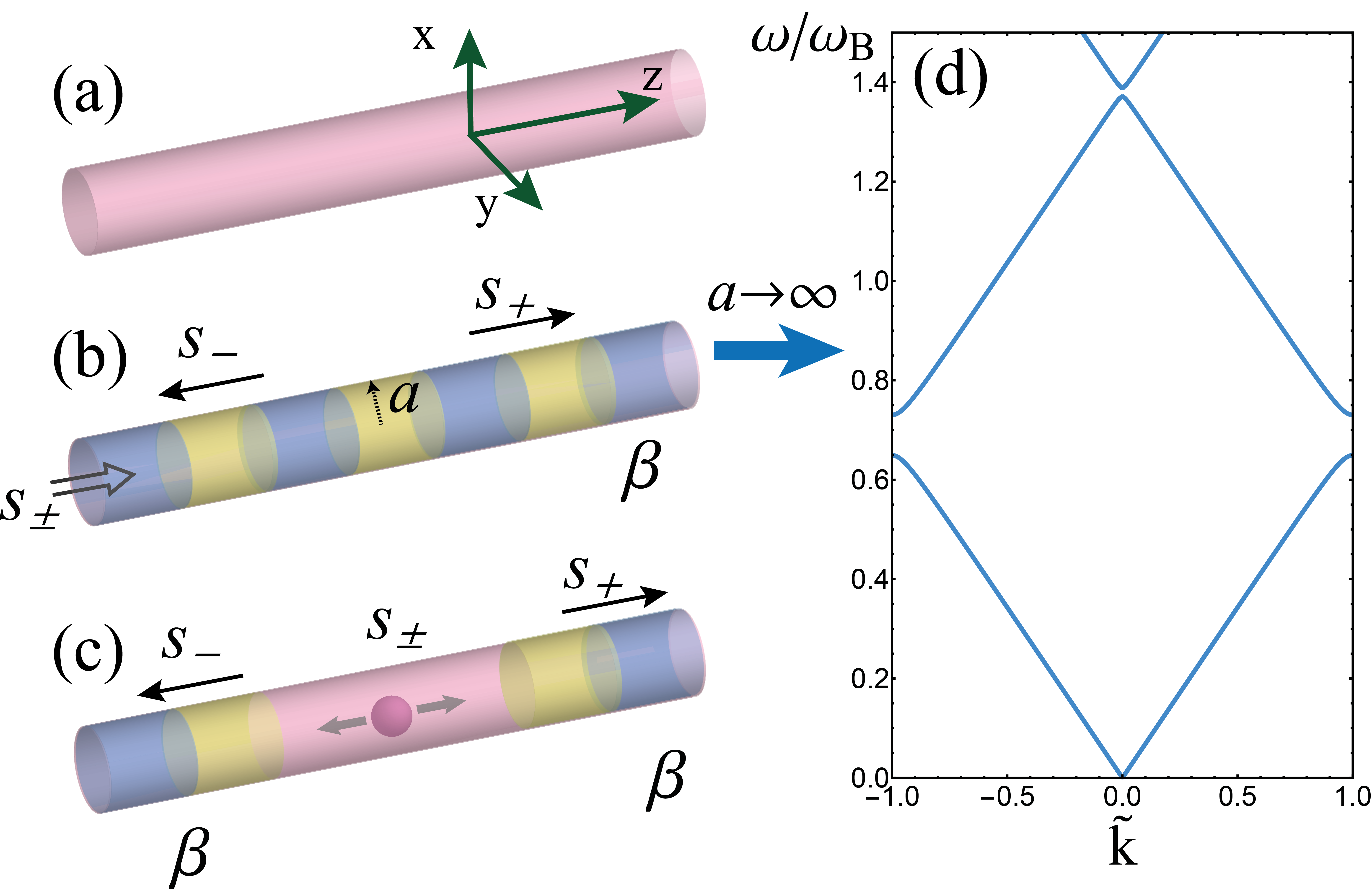
Floquet theory and dispersion relation. Let’s consider an infinite cylindrical waveguide with weak Bragg grating along the direction [Fig. 1(a,b)]. Its relative permittivity has spatial variation and can be written as:
| (1) |
where is the Heaviside step function, is the waveguide radius, and represents the spatial frequency of the Bragg grating, and are two constants with , and are cylindrical coordinate variables.
In what follows we shall calculate eigenmodes of the waveguide for corresponding . By setting the time dependence of the electric field as , satisfies a vector Helmholtz equation JacksonBook . In cylindrical coordinate, the vector Laplacian operator can be separated into transverse and longitudinal components (see the Supplemental Material); and specifically, the component of the electric field fulfills the equation
| (2) |
where is the speed of light and the relative permeability is assumed. Separating the coordinate variable dependency as , for , we have
| (3) |
The solution for satisfies , with the quantum number of the angular momentum operator LearyPRA14 . The function satisfies
| (4) |
is a variable separation constant that does not depend on any coordinate variables. Eq.(4) is the Mathieu equation MathieuEquation , which has a general solution
| (5) |
where and are the Mathieu cosine and sine functions respectively, , , and are constants.
Now we are ready to obtain the general solution of . Inserting Eq.(4) into Eq.(3), the function satisfies the Bessel equation and can be written as , where is the Bessel function of the first kind and , for . A similar procedure can be done for , with , and is the modified Bessel function of the second kind and .
Having now the expression of , we can insert it into the Maxwell equations to calculate the transverse component and JacksonBook . Since the amplitude of the Bragg modulation is assumed to be weak, as a zeroth order approximation , Eq. (4) reduces to whose solution is , giving the usual homogeneous waveguide result. In this case, we obtain the well known HE/EH mode dispersion relation JacksonBook ; KienPRA17 :
| (6) |
where and are the refractive indices inside and outside the waveguide, respectively.
In the homogeneous case, bears two roles simultaneously: first, as a variable separation constant; and second, as the Floquet exponent. Once the Bragg modulation is introduced, the degeneracy of those two roles breaks down so that is no longer a good quantum number representing correctly the momentum of the light field. Hence, the relation is not the proper dispersion relation for . In order to calculate the correct dispersion relation, we need to apply the Floquet theory explicitly.
According to the Floquet’s theorem, the solutions of the Mathieu equation Eq. (5) can be written in the form MathieuEquation
| (7) |
where is the Mathieu characteristic exponent and is a periodic function with the period FloquetTheory . In the form of Eq.(7), we can see that the correct momentum quantum number is rather than , and the relation is the true dispersion relation for the Bragg modulation.
Therefore, we need to eliminate the intermediate parameter in order to obtain the dispersion. As an example, let’s consider the case where the system reduces to an 1D photonic crystal (with planar slabs). For the TE/TM mode, the relation is given by JoannopoulosBook08 , which is a linear relation and does not contain any discontinuity. Meanwhile, by using Eq. (7), can be inversely expressed as , where is an analytic function defined by series expansions MathieuFunction . By matching two expressions of , we have
| (8) |
This is an implicit expression of the desirable dispersion relation. Fig. 1(d) shows the numerically calculated dispersion curve by using Eq. (8). This semi-analytical result matches nicely the existing results obtained from ab initio calculations in photonic crystal literature JoannopoulosBook08 .
Now we consider Bragg modulations inside a waveguide with a finite radius . For a given waveguide mode with angular momentum and a given order of the solution, e.g. HE31 mode, to obtain the dispersion relation the calculation procedure would be similar: first we calculate its relation by using Eq. (6) KienPRA17 , and then eliminate the dependency by using Eq. (8). Besides the existence of a cut-off frequency for certain modes JacksonBook , the resulting dispersion curve will possess the band gap structure introduced by the Bragg modulation. Note that the transversely confined periodic structure can support bound states in the continuum BulgakovPRA17 , however, since those modes lie above the light line, they are outside the scope of our consideration.
SOI corrections. Next we consider the effect of the SOI on the band gap. Here we only consider fiber modes with paraxial light where its spin and the intrinsic orbital angular momentum are separable VitulloPRL17 ; EnkEurLett94 . In this case, the angular momentum is parallel to the propagation direction and is represented by the operator whose eigenvalue is . Recent experiments VitulloPRL17 have demonstrated that for a homogeneous cylindrical waveguide, the transverse confinement will result in a SOI correction term for the transverse electric field (see the Supplemental Material):
| (9) |
where is the transverse Laplacian, is the effective SOI interaction LearyPRA14 :
| (10) |
where is the dielectric jump on the waveguide boundary; and are the spin and orbital angular momentum operators respectively. They are both defined against the axis of the laboratory frame.
One can see that Eq. (9) be seen as satisfying a vector Helmholtz equation with eigenvalues , while is added as a perturbation. The perturbation against the eigenvalue can be conveniently calculated in the helicity basis LearyPRA14 , where represents the right- and left- handedness of a photon’s helicity and are the basis vectors of the Cartesian coordinate system. Up to the first order, assuming in the helicity basis, perturbations to read LearyPRA14 :
| (11) |
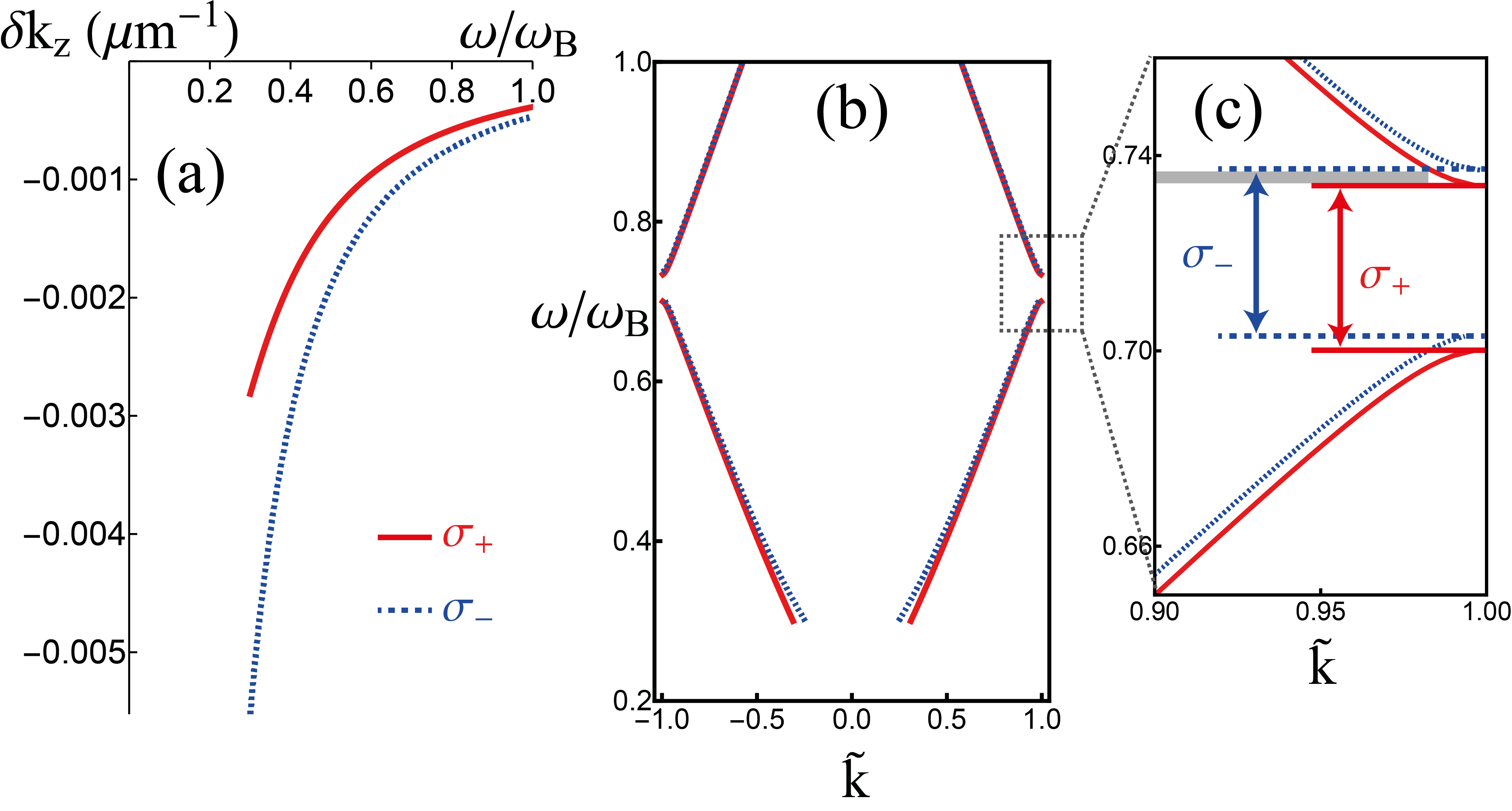
The corrected eigenvalues (where is the unperturbed eigenvalue) signify a splitting between the and components, which has been observed in experiments as the rotation of the spatial intensity pattern given by the interference of two beams with opposite orbital angular momentum LearyPRA14 ; VitulloPRL17 . Fig. 2(a) shows the dependence of the SOI correction on for the HE31 mode away from the cut-off frequency, where the absolute value of is about of the original eigenvalue .
Now we combine the SOI correction Eq. (11) with the Bragg modulation. The splitting in gives rise to the splitting of the Floquet characteristic exponent . If the zeroth order relation of the HE31 mode is denoted as , then according to Eq. (7), the shifted dispersion is given by
| (12) |
Therefore, the photonic band gap will be shifted correspondingly. Fig. 2(b)(c) shows the calculated split band gap structure. Represented by the grey area, the gap shift under current parameters is about , which is about THz.
The split band gap between helicity and leads to a single propagation channel within a certain range of frequency. For example, as it is illustrated in Fig. 1(b), when a Laguerre-Gauss beam couples to the waveguide and generates the targeted waveguide mode VitulloPRL17 , in the shaded frequency area in Fig. 2(c) only can propagate, while will be reflected. When we transfer back to the laboratory basis and observe the spin (denoted by ), since the spin flips upon reflection by the gap, the final result is the spin-direction-locked propagation similar to that of CQO configurations. But it does not require any atom coupling to achieve chiral response.
To achieve the single-photon spin splitter, a single photon emitter/coupler AharonovichNatPho16 ; PetersenScience14 can be placed in the middle of the waveguide [Fig. 1(c)]. Within a suitable frequency range, detectors on each side of the waveguide will receive spin-locked signals. Compared to macrosopic polarizing filters, the merit of our structure is that it is based on the intrinsic SOI and can work in the nano-scale which is a crucial prerequisite in the field of integrated photonics.
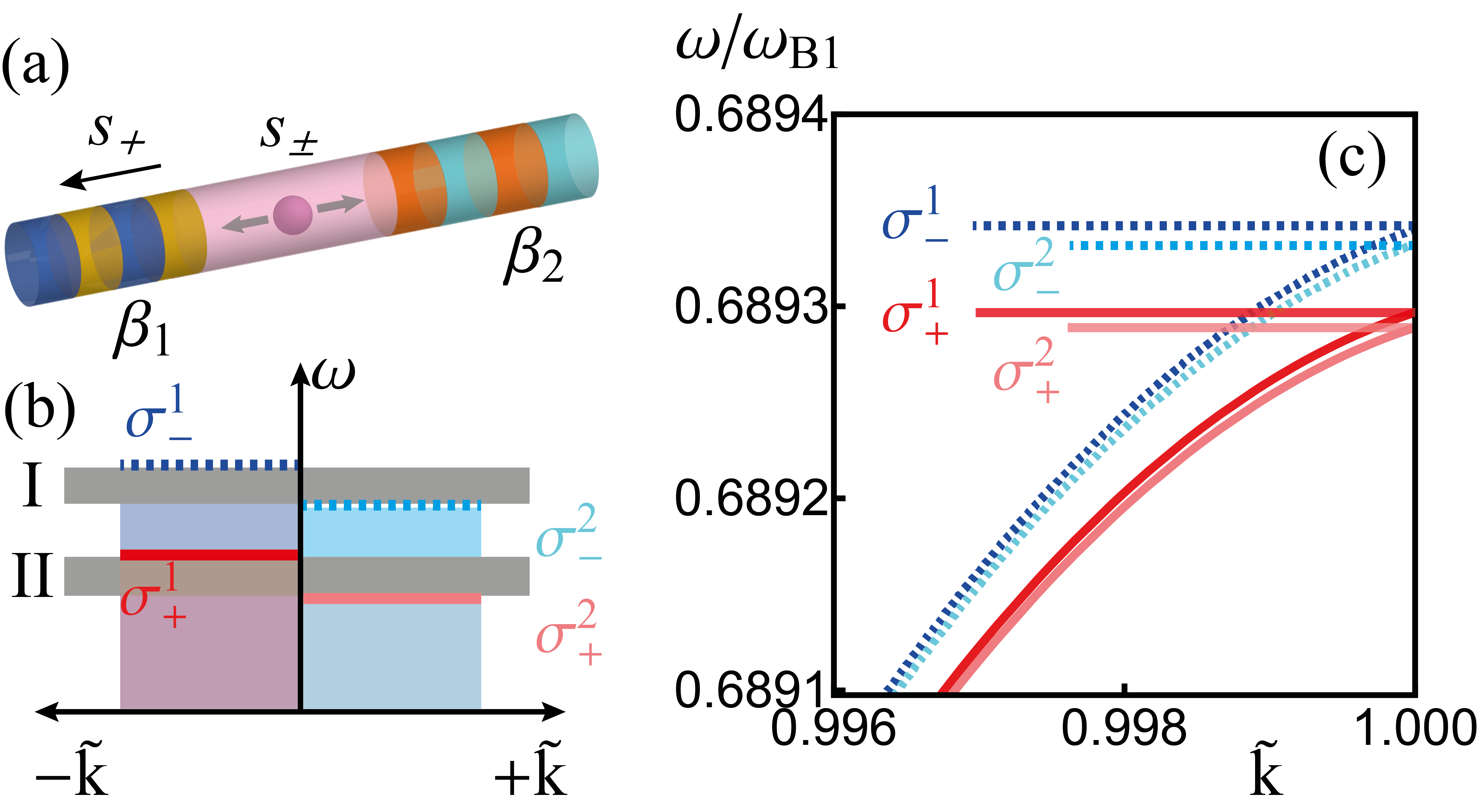
Further, the single photon emitter can be placed between two blocks of Bragg modulations with slightly different spatial modulation frequency or amplitude, as illustrated in Fig. 3(a). In this case, the band gaps for and will be different (calculated in helicity basis). Fig. 3(c) shows an example calculation for the lower side of a band gap, where curves with darker colors are for left block (toward ) and curves with lighter colors are for the right block (toward ). In both blocks, are split by the SOI effect so that there are four shifted band gaps to consider. A simplified illustration is shown in Fig. 3(b), where the lower boundary of a band gap is shown by solid or dashed lines, and the shaded areas are the corresponding dielectric bands where light can propagate through JoannopoulosBook08 .
Figure 3(a) shows the effect when light is emitted within the frequency region I listed in Fig. 3(b). In this frequency range, only can propagate toward direction. Seen in the laboratory basis, only the can be detected on the left side of the waveguide, while other polarization components will be trapped within the effective microcavity formed by two blocks of Bragg modulations. Similarly, in frequency region II in Fig. 3(b), only propagating toward the positive direction will be blocked, while all other polarization components can propagate freely. This single-channel photon emission/blockage design can be implemented in quantum computation, spectroscopy and metrology, where directional emission of photons are vital LounisRPP05 ; PolyakovJMO09 .
In summary, we proposed a fully optical design for a single-photon spin splitter based on the SOI of light originating from the transverse confinement of a cylindrical waveguide. The SOI leads to a splitting between the propagation constant between the helicity and components. When a Bragg modulation of the dielectric constant is included, one needs to eliminate to obtain the genuine dispersion relation, where is the Floquet exponent. The SOI splitting in results in splitting in the dispersion and the splitting of the photonic band gap between two helicity components. When viewed in the laboratory basis, the split band gap provides a spin-locked propagation channel for two polarization states or , forming the single-photon spin splitter.
The calculation procedure we proposed can be used to investigate the unidirectional invisibility LinPRL11 resulting from a parity () and time () symmetric dielectric distribution . In this case, the function in Eq. (4) allows analytic solutions, hence its dispersion between the Floquet exponents and frequency can be calculated explicitly (see Supplementary Material). By studying the properties of the Floquet exponents, we might obtain insight into the spectral singularities AliPRL09 ; AliPRA11 resulting from the complex -symmetric potentials.
Acknowledgements.
G.L. acknowledges the EPSRC Programme on Hybrid Polaritonics for financial support and thanks Dr Ben Hopkins for useful discussions. AK acknowledges the support from the Russian Foundation for Basic Research (RFBR) and Deutsche Forschungsgemeinschaft (DFG) in the framework of International Collaborative Research Center TRR 160 (Project No. 15-52-12018). The work was carried out with financial support from the Ministry of Education and Science of the Russian Federation in the framework of increase Competitiveness Program of NUST ”MISIS”, implemented by a governmental decree dated 16th of March 2013, No 211.References
- (1) P. Lodahl, S. Mahmoodian, S. Stobbe, A. Rauschenbeutel, P. Schneeweiss, J. Volz, H. Pichler, and P. Zoller. Chiral quantum optics. Nature 541, 473 (2017).
- (2) A. Aiello, P. Banzer, M. Neugebauer, and G. Leuchs, From transverse angular momentum to photonic wheels. Nat. Photon. 9, 789 (2015).
- (3) K. Y. Bliokh and F. Nori. Transverse and longitudinal angular momenta of light. Phys. Rep. 592, 1 (2015).
- (4) K. Y. Bliokh, D. Smirnova, and F. Nori. Quantum spin Hall effect of light. Science 348, 1448 (2015).
- (5) I. J. Luxmoore, N. A. Wasley, A. J. Ramsay, A. C. T. Thijssen, R. Oulton, M. Hugues, S. Kasture, V. G. Achanta, A. M. Fox, and M. S. Skolnick. Interfacing Spins in an InGaAs Quantum Dot to a Semiconductor Waveguide Circuit Using Emitted Photons. Phys. Rev. Lett. 110, 037402 (2013).
- (6) C. Junge, D. O’Shea, J. Volz, and A. Rauschenbeutel. Strong Coupling between Single Atoms and Nontransversal Photons. Phys. Rev. Lett. 110, 213604 (2013).
- (7) K. Y. Bliokh, F. J. Rodríguez-Fortuño, F. Nori, and A. V. Zayats. Spin–orbit interactions of light. Nat. Photon. 9, 396 (2015).
- (8) M. Onoda, S. Murakami, and N. Nagaosa. Hall Effect of Light. Phys. Rev. Lett. 93, 083901 (2004).
- (9) K. Y. Bliokh and Y. P. Bliokh. Conservation of Angular Momentum, Transverse Shift, and Spin Hall Effect in Reflection and Refraction of an Electromagnetic Wave Packet. Phys. Rev. Lett. 96, 073903 (2006).
- (10) O. Hosten and P. Kwiat, Observation of the spin Hall effect of light via weak measurements. Science 319, 787 (2008).
- (11) A. Aiello and J. P. Woerdman. Role of beam propagation in Goos-Hänchen and Imbert–Fedorov shifts. Opt. Lett. 33, 1437 (2008).
- (12) K. Y. Bliokh, A. Niv, V. Kleiner and E. Hasman. Geometrodynamics of spinning light. Nature Photon. 2, 748 (2008).
- (13) Y. Gorodetski, K. Y. Bliokh, B. Stein, C. Genet, N. Shitrit, V. Kleiner, E. Hasman, and T. W. Ebbesen. Weak measurements of light chirality with a plasmonic slit. Phys. Rev. Lett. 109, 013901 (2012).
- (14) K. Y. Bliokh and A. Aiello, Goos-Hänchen and Imbert-Fedorov beam shifts: An overview. J. Opt. 15, 014001 (2013).
- (15) A. Dogariu and C. Schwartz. Conservation of angular momentum of light in single scattering. Opt. Express 14, 8425 (2006).
- (16) Y. Zhao, J. S. Edgar, G. D. M. Jeffries, D. McGloin, and D. T. Chiu. Spin-to-Orbital Angular Momentum Conversion in a Strongly Focused Optical Beam. Phys. Rev. Lett. 99, 073901 (2007).
- (17) K. Y. Bliokh, E. A. Ostrovskaya, M. A. Alonso, O. G. Rodríguez-Herrera, D. Lara, and C. Dainty. Spin-to-orbital angular momentum conversion in focusing, scattering, and imaging systems. Opt. Express 19, 26132 (2011).
- (18) R. Mitsch, C. Sayrin, B. Albrecht, P. Schneeweiss, and A. Rauschenbeutel. Quantum state-controlled directional spontaneous emission of photons into a nanophotonic waveguide. Nat. Commun. 5, 5713 (2014).
- (19) I. Shomroni, S. Rosenblum, Y. Lovsky, O. Bechler, G. Guendelman, and B. Dayan. All-optical routing of single photons by a one-atom switch controlled by a single photon. Science 345, 903 (2014).
- (20) Larry A. Coldren and Scott W. Corzine. Diode Lasers and Photonic Integrated Circuits, 2nd, Wiley-Blackwell US (2012).
- (21) C. C. Leary, M. G. Raymer, and S. J. van Enk. Spin and orbital rotation of electrons and photons via spin-orbit interaction. Phys. Rev. A 80, 061804(R)(2009).
- (22) C. C. Leary and Karl H. Smith. Unified dynamics of electrons and photons via Zitterbewegung and spin-orbit interaction. Phys. Rev. A 89, 023831 (2014).
- (23) D. L. P. Vitullo, C. C. Leary, P. Gregg, R. A. Smith, D. V. Reddy, S. Ramachandran, and M. G. Raymer. Observation of Interaction of Spin and Intrinsic Orbital Angular Momentum of Light. Phys. Rev. Lett. 118, 083601 (2017).
- (24) J. D. Joannopoulos, S. G. Johnson, J. N. Winn, and R. D. Meade. Photonic Crystals: Molding the Flow of Light, 2nd, Princeton University Press (2008).
- (25) M. Gagné, S. Loranger, J. Lapointe, and R. Kashyap. Fabrication of high quality, ultra-long fiber Bragg gratings: up to 2 million periods in phase. Opt. Express 22, 387 (2014).
- (26) Yu.V. Komlenko. Floquet theory. Encyclopedia of Mathematics, Facts on File (2005).
- (27) E. W. Weisstein. Floquet’s Theorem. From MathWorld–A Wolfram Web Resource. http://mathworld.wolfram.com/FloquetsTheorem.html
- (28) Tyn Myint-U and Lokenath Debnath. Linear Partial Differential Equations for Scientists and Engineers, 4th, Birkhäuser Boston (2007).
- (29) L. Carretero, M. Perez-Molina, P. Acebal, S. Blaya, A. Fimia. Matrix method for the study of wave propagation in one-dimensional general media. Opt. Express 14, 11385 (2006).
- (30) P. Pereyra. An Improved Theoretical Approach to Study Electromagnetic Waves through Fiber Bragg Gratings. Adv. Cond. Matter Phys. 2017, 4824921 (2017).
- (31) J. D. Jackson. Classical Electrodynamics, 3rd, Wiley (1998).
- (32) E. W. Weisstein. Mathieu Differential Equation. From MathWorld–A Wolfram Web Resource.
- (33) Gertrude Blanch. Chapter 20. Mathieu Functions. Handbook of Mathematical Functions with Formulas, Graphs, and Mathematical Tables, Dover: New York (1972).
- (34) F. L. Kien, T. Busch, V. G. Truong, and S. N. Chormaic. Higher-order modes of vacuum-clad ultrathin optical fibers. Phys. Rev. A 96, 023835 (2017).
- (35) E. N. Bulgakov and A. F. Sadreev. Bound states in the continuum with high orbital angular momentum in a dielectric rod with periodically modulated permittivity. Phys. Rev. A 96, 013841 (2017).
- (36) S. J. van Enk and G. Nienhuis, Spin and orbital angular momentum of photons, Europhys. Lett. 25, 497 (1994).
- (37) I. Aharonovich, D. Englund, and M. Toth. Solid-state single-photon emitters. Nat. Photonics 10, 631 (2016).
- (38) J. Petersen, J. Volz, and A. Rauschenbeutel. Chiral nanophotonic waveguide interface based on spin-orbit interaction of light. Science 346, 67 (2014).
- (39) B. Lounis, and M. Orrit. Single-photon sources. Rep. Prog. Phys. 68, 1129 (2005).
- (40) S. V. Polyakov and A. L. Migdall. Quantum radiometry. J. Mod. Opt. 56, 1045 (2009).
- (41) Zin Lin, Hamidreza Ramezani, Toni Eichelkraut, Tsampikos Kottos, Hui Cao, and Demetrios N. Christodoulides. Unidirectional Invisibility Induced by -Symmetric Periodic Structures. Phys. Rev. Lett. 106, 213901 (2011).
- (42) Ali Mostafazadeh. Spectral Singularities of Complex Scattering Potentials and Infinite Reflection and Transmission Coefficients at Real Energies. Phys. Rev. Lett. 102, 220402 (2009).
- (43) Ali Mostafazadeh. Optical spectral singularities as threshold resonances. Phys. Rev. A 83, 045801 (2011).