The Herschel-PACS legacy of low-mass protostars:
Properties of warm and hot gas and its origin in far-UV illuminated shocks
Abstract
Recent observations from Herschel allow the identification of important mechanisms responsible for the heating of gas surrounding low-mass protostars and its subsequent cooling in the far-infrared (FIR). Shocks are routinely invoked to reproduce some properties of the far-IR spectra, but standard models fail to reproduce the emission from key molecules, e.g. H2O. Here, we present the Herschel-PACS far-IR spectroscopy of 90 embedded low-mass protostars (Class 0/I). The Herschel-PACS spectral maps covering m with a field-of-view of 50” are used to quantify the gas excitation conditions and spatial extent using rotational transitions of H2O, high- CO, and OH, as well as [O I] and [C II]. We confirm that a warm (300 K) CO reservoir is ubiquitous and that a hotter component ( K) is frequently detected around protostars. The line emission is extended beyond 1000 AU spatial scales in 40/90 objects, typically in molecular tracers in Class 0 and atomic tracers in Class I objects. High-velocity emission ( km s-1) is detected in only 10 sources in the [O I] line, suggesting that the bulk of [O I] arises from gas that is moving slower than typical jets. Line flux ratios show an excellent agreement with models of -shocks illuminated by UV photons for pre-shock densities of cm-3 and UV fields 0.1-10 times the interstellar value. The far-IR molecular and atomic lines are a unique diagnostic of feedback from UV emission and shocks in envelopes of deeply embedded protostars.
1 Introduction
Complex physical processes are at play during the earliest stages of low-mass star formation, when high accretion rates translate to significant feedback from a protostar on its surroundings (e.g. Frank et al., 2014). The launching of collimated jets and wide-angle winds leads to the formation of outflow cavities, and generates shock waves that compress and heat the envelope material to hundreds or thousands of K (Neufeld & Dalgarno, 1989; Arce et al., 2007). Ultraviolet (UV) photons produced as a result of accretion onto the protostar and created in shocks penetrate to large distances due to the low densities and scattering by dust in the outflow cavities (Spaans et al., 1995; van Kempen et al., 2010b; Visser et al., 2012). As a result, the gas around low-mass protostars is heated to hundreds of K, altering the chemistry and physics of the available mass reservoir and lowering the efficiency of star formation (e.g. Offner et al., 2009; Drozdovskaya et al., 2015).
Previous studies of feedback from low-mass protostars concentrated on the low-temperature ( K) gas probed by low- () rotational transitions of CO at submillimeter wavelengths (e.g. Bachiller & Tafalla, 1999; Arce et al., 2007; van der Marel et al., 2013; Dunham et al., 2014; Yıldız et al., 2015). Those transitions trace the entrained outflow gas but show significant differences in spatial extent of emission and line profiles with respect to the more highly-excited lines (Nisini et al., 2010; Santangelo et al., 2014b; Kristensen et al., 2013, 2017b). Thus, the energetic processes seen in high- CO lines () are likely different and need to be characterized separately.
The most efficient cooling of hot and dense gas occurs in the far-infrared (IR) domain and thus the best tracers of the heating mechanisms are rotational lines of H2O, high- CO, OH, and forbidden transitions of [O I] and [C II] (Goldsmith & Langer, 1978; Hollenbach et al., 1989). The first multi-line surveys of low-mass protostars were performed using the Long-Wavelength Spectrometer onboard the Infrared Space Observatory (Kessler et al., 1996; Clegg et al., 1996). The line spectra showed rich molecular emission which is spatially extended along the outflow direction and excited in relatively dense ( cm-3) and warm ( K) gas (Giannini et al., 2001; Nisini et al., 2002). A combination of a slow, non-dissociative shock and a fast, dissociative shock from the jet was invoked to explain the observed molecular and [O I] emission, respectively. Yet, the low sensitivity of the instrument and the large telescope beam () covering the entire extent of young stellar objects prevented study of the location of the far-IR emission.
Far-IR spectral maps from the Photodetector Array Camera and Spectrometer (PACS; Poglitsch et al., 2010) on board the Herschel Space Observatory (Pilbratt et al., 2010)111Herschel was an ESA space observatory with science instruments provided by European-led Principal Investigator consortia and with important participation from NASA. are well-suited to revisit the ISO/LWS results due to enhanced sensitivity, along with improved spatial and spectral resolution. The array of elements covered a total field of view of with pixels, corresponding to the spatial resolution scales of order AU at the typical distances to nearby protostars (200 pc).
Three large surveys of nearby low-mass protostars were carried out using Herschel. The ‘Water in Star forming regions with Herschel’ (WISH) survey focused on H2O and related species to characterize the physical and chemical processes in about 80 low-, intermediate-, and high-mass young stellar objects from pre-stellar cores to disks (van Dishoeck et al., 2011) using mostly high-resolution spectra from the Heterodyne Instrument for the Far-Infrared (HIFI, de Graauw et al., 2010). The PACS spectra centered at protostar position were obtained for 18/29 deeply-embedded low-mass protostars, typically at selected transitions (Karska et al., 2013). The ‘Dust, Ice, and Gas in Time’ (DIGIT) open time program obtained complementary, full PACS spectra toward 30 Class 0/I protostars to quantify the dust and gas evolution in the far-IR (Green et al., 2013, 2016), including 8 overlap sources with the WISH survey. Finally, the ‘William Herschel Line Legacy’ (WILL) open time survey (Mottram et al. 2017) obtained PACS and HIFI spectra toward about 50 additional low-mass protostars from the recent Spitzer and Herschel Gould Belt imaging surveys (e.g. Evans et al., 2009; André et al., 2010; Dunham et al., 2015). The WILL survey balances the samples of the WISH and DIGIT surveys both in the evolutionary stage (Class 0/I) and luminosities of protostars, thus ensuring that the combined sample of these three surveys is more representative of the general population of low-mass protostars (see Mottram et al., 2017, for details).
Additional surveys focused on populations of protostars in specific clusters, located at similar distances. As part of the ‘Herschel Orion Protostar Survey’, CO emission covering the full PACS range was characterized for 21 protostars in Orion (Manoj et al., 2013, 2016). Far-IR emission maps for the eight, youngest protostars identified in this survey (Stutz et al., 2013, the PACS Bright Red Sources, PBRSs), were analyzed by Tobin et al. (2016a). The ‘Herschel Study of Star Formation Feedback on Cloud Scales’ (PI: H. Arce) obtained PACS and HIFI maps of the entire NGC1333 region in Perseus in the selected atomic ([O I], [C II]) and molecular lines (e.g. CO 10-9, H2O 557 GHz), respectively (Dionatos & Güdel, 2017). Riviere-Marichalar et al. (2016) provide a catalog of H2O and [O I] lines observed with PACS for 362 young stellar objects from Class 0 to Class III.
The above programs have proven H2O as an important tracer of energetic physical processes in the earliest stages of star formation. Line profiles of H2O are complex, but dominated by gas moving at several tens of km s-1 (Kristensen et al., 2012; Mottram et al., 2014, 2017). The spatial extent of H2O resembles the emission from H2 and follows the outflow direction (Nisini et al., 2010; Santangelo et al., 2012). The far-IR gas cooling budget is dominated by H2O and high- CO lines, following the predictions from models of non-dissociative, shocks (Karska et al., 2013). Thus, H2O emission is closely linked to the outflow shocks and its excitation is in agreement with stationary (1D plane-parallel) shock models (e.g. Paris-Durham code, Flower & Pineau des Forêts, 2015). Yet, these models cannot reproduce the chemistry: low abundances of H2O and O2 and low H2O / CO and H2O / OH flux ratios (Melnick & Kaufman, 2015; Karska et al., 2014b). UV photons can photodissociate H2O and reconcile the models and observations, but the models of shocks irradiated by UV have not been available for detailed comparisons until now.
In this paper, we analyze together the far-IR PACS spectra of a large and uniform sample of low-mass YSOs obtained as part of the WISH, DIGIT, and WILL surveys, and compare them to the stationary shock models from Flower & Pineau des Forêts (2015), models of photodissociation regions from Kaufman et al. (1999), and UV irradiated -shock models from Melnick & Kaufman (2015) to address the following questions: What is the typical far-IR spectrum of a low-mass protostar? Is the emission in various far-IR atomic and molecular species linked? What is the spatial extent of the line emission? What are the typical rotational temperatures of CO, H2O, and OH, and the corresponding physical conditions of the gas? What is the gas cooling budget in the far-IR? What is the origin of the far-IR emission? In particular, what kinds of shocks and densities of pre-shock material are involved? What is the strength of UV radiation and does it affect the chemistry of low-mass protostars? Finally, what is the evolution of the far-IR line properties during the Class 0/I phases and the corresponding changes in the physical processes (shocks, UV radiation)?
The paper is organized as follows. §2 describes our sample selection, observations, and data reduction. §3 compiles results on detection statistics, spatial extent of line emission and resolved profiles. §4 shows analysis of molecular excitation and far-infrared line cooling. Comparisons of absolute line emission of atomic lines to shocks and photodissociation regions models are presented in §5, along with comparisons to UV-illuminated shock models. §6 discusses the results obtained in previous sections and §7 presents the summary and conclusions.
2 Observations
2.1 Sample selection
The low-mass embedded protostars analyzed here were initially observed as part of the ‘Water In Star forming regions with Herschel’ (WISH, van Dishoeck et al., 2011) and ‘Dust, Ice, and Gas In Time’ (DIGIT, Green et al., 2013) surveys, which comprised 18 and 29 protostars targeted with PACS, respectively, including 8 overlap sources. This sample was subsequently expanded by the ‘William Herschel Line Legacy’ survey (WILL, Mottram et al. 2017), where a further 49 sources were observed, including 37 Class 0/I objects. Three additional sources were located in the PACS spectral maps of the primary targets, increasing the sample to 90 sources in total (for details, see Table 1).

Most of the sources are located in the Perseus (30 sources), the Aquila Rift complex (7 sources in W40, 6 sources in Aquila, and 2 sources in Serpens South), and Taurus (12 sources). The remaining sources are from Ophiuchus (9 sources), Corona Australis (5 sources), Serpens Main (3 sources), and other molecular clouds. All protostars are located at distances pc (for distance references see Kristensen et al., 2012; Green et al., 2013; Mottram et al., 2017).
The selection procedures for the WISH and DIGIT sources are discussed in detail in van Dishoeck et al. (2011) and Green et al. (2013) with a general rule that all of them are well-known and extensively studied protostars. The WILL sources were selected based on unbiased mid-IR and millimeter continuum observations with Spitzer and various ground-based telescopes (Mottram et al., 2017).
The sources are divided into classes based on the shapes of their spectral energy distributions (SEDs), constructed using flux densities obtained with Herschel-PACS (see Karska et al. 2013 for WISH, Green et al. 2016 and Manoj et al. 2016 for DIGIT, Mottram et al. 2017 for WILL). Sources with bolometric temperatures K are classified as Class 0, and those with K are classified as Class I. However, 12 sources in the original WILL sample were re-classified as either Class II or pre-stellar, based on the absence of an entrained molecular outflow as identified by broad line wings in CO 3-2 maps and in HIFI H2O and CO 10-9 spectra, as well as on the morphology and intensity of HCO+ 4-3 and C18O 3-2 emission (see Mottram et al. 2017 and the description of the method in van Kempen et al. 2009a and Carney et al. 2016). Additionally, in 5 out of those 12 sources and in one Class 0 source, Mottram et al. (2017) detected a narrow, bright CO 10-9 emission indicative of photodissociation regions (PDRs) that are not associated with young stellar objects. Excluding pre-stellar, Class II and PDRs, the final sample consists of 42 Class 0 and 35 Class I sources, covering a broad range of bolometric luminosities, (see Figure 1). The comparison with the global Spitzer Gould Belt sample shows that the sample here is representative for the Class 0 and young Class I sources (Mottram et al., 2017).
We note that in the three sources (ID numbers 4, 82, 85), the separation of protostars is large enough to decompose the continuum emission from PACS spectral maps into distinct objects (see Lee et al. 2013 for L1448 MM and Lindberg et al. 2014 for sources in Corona Australis). The rest of the sources are treated as single objects, even though some of them are close multiples (e.g. Tobin et al., 2016b). The impact of this treatment depends on the evolutionary stage and relative brightness of the respective components. Murillo et al. (2016) distinguish three cases: (i) the combined SED is simply doubled when the two components have similar SEDs; (ii) the SED appears odd, double-peaked when the two components are non-coeval; (iii) the brightest component dominates the combined SED, when the other one is noticeable dimmer and younger. Similar cases are expected to apply for the emission lines. However, without a strong indication that the sources are co-eval, the calculated luminosities cannot be properly corrected (Murillo et al., 2016), and the sources are therefore treated as single sources in the following.
2.2 Observations and data reduction
Single footprint spectral maps of all sources were obtained with the PACS instrument onboard Herschel. Each map consists of 25 spatial pixels (spaxels) of arranged in a 55 array with a total field of view of . Each spaxel contains a (sub-)spectrum observed in the first (red) or second (blue) order, within the wavelength ranges of 102-210 m and 51-105 m, respectively. Due to flux calibration issues at the extreme ends of the spectra, the ranges from 55-100 m and 104-190m are used in the analysis. The spectral resolving power increases with wavelength from about 1000 to 2000 (corresponding to velocity resolutions of 140 to 320 km s-1) in the first order and from about 1500 to 3000 (100 to 210 km s-1) in the second order.
Two main observing schemes were used: line spectroscopy mode for the WISH and WILL sources; and range spectroscopy mode for the DIGIT sources and four sources from the WISH survey (Serpens SMM1 and NGC1333 IRAS 4A, 4B, and 2A). The line spectroscopy mode yields observations of small spectral regions (0.5-2 m) around selected lines and is particularly suited for deep integrations. The range spectroscopy mode provides the full spectrum from to 210 m but the spectral sampling within a resolution element is about 3-4 times coarser than in the line spectroscopy mode. For both schemes, the chopping / nodding observing mode from the source was used to subtract the background emission within 6′.
Data reduction for both observing modes was performed with the Herschel Interactive Processing Environment (HIPE, Ott, 2010) version 13. The flux was normalized to the telescopic background and calibrated using observations of Neptune. Spectral flatfielding within HIPE was used to increase the signal-to-noise ratio (for details, see Herczeg et al. 2012, Green et al. 2013, and Sturm et al. 2013). The overall flux uncertainty is about 20% from cross-comparisons of sources in common within our programs.
A 1D spectrum is obtained for each source by summing a custom number of spaxels chosen after investigation of the 2D spectral maps (Karska et al., 2013), using the technique applied to the “CDF” (COPS-DIGIT-FOOSH protostar) archive (Green et al., 2016). This archive is freely available as a User Provided Data Product in the Herschel Science Archive222https://www.cosmos.esa.int/web/herschel/user-provided-data-products. Most notably, the 2016 update in PACS spectroscopy includes a correction for pointing and jitter offsets during observations.
For sources with extended line emission, the co-addition of spaxels with detected emission increases the S / N, smooths the continuum, and enables correction for significant differences in beam sizes over the wide spectral range covered by PACS. For sources with point-like emission in all lines, only the central spaxel spectrum is used, but the line fluxes are multiplied by the wavelength-dependent instrumental correction factors ( at 70 m and at 180 m, see PACS Observer’s Manual333http://herschel.esac.esa.int/Docs/PACS/html/pacs_om.html).
Since the lines are spectrally unresolved (except [O I], see §3.3), line fluxes are calculated by fitting Gaussians to the final 1D spectrum. Single Gaussians are used for well-isolated lines and double or triple Gaussians for closeby lines, including blends. The line width of the Gaussians is fixed to the instrumental value for unresolved lines, except the [O I] line at 63 m which in several sources shows high-velocity wings (van Kempen et al., 2010b; Karska et al., 2013; Riviere-Marichalar et al., 2016). In this case, integration and / or broad Gaussian fitting are applied. All Gaussian fits were visually inspected to avoid possible confusion.
| ID | RA (J2000) | Dec (J2000) | Cloud | aaDistances come from van Dishoeck et al. (2011) for the WISH sources, Green et al. (2013) for the DIGIT sources, and Mottram et al. (2017) for the WILL sources with the exception of sources in Serpens, which have been updated to use the latest distance by Ortiz-León et al. (2017). PS refers to possible pre-stellar cores and PDR to photodissociation regions. | Class | Other names | SurveybbSurvey names refer to: D - DIGIT, WH - WISH, and WL - WILL programs on Herschel. | |||
|---|---|---|---|---|---|---|---|---|---|---|
| (hms) | (° ′ ″) | (pc) | () | (%) | (K) | |||||
| 1 | 03 25 22.33 | 30 45 14.0 | Per | 235 | 4.5 | 2.7 | 44 | 0 | L1448 IRS2, Per-emb 22, PER 01 | WL |
| 2 | 03 25 36.48 | 30 45 22.3 | Per | 235 | 9.2 | 1.7 | 54 | 0 | L1448 IRS3/N(A), Per-emb 33, PER 02 | WL |
| 3 | 03 25 38.82 | 30 44 06.3 | Per | 235 | 5.5 | 0.4 | 49 | 0 | L1448 MMS/C(N), Per-emb 26 | D |
| 4 | 03 25 39.10 | 30 43 58.0 | Per | 235 | 1.7 | 2.1 | 80 | I | L1448 C(S), Per-emb 42 | D |
| 5 | 03 26 37.46 | 30 15 28.0 | Per | 235 | 1.2 | 4.2 | 60 | 0 | I032353004, Per-emb 25, PER 04 | WL |
| 6 | 03 27 39.09 | 30 13 03.0 | Per | 235 | 6.6 | 1.3 | 48 | I | L1455-IRS1, I032453002, Per-emb 17 | D |
| 7 | 03 28 00.40 | 30 08 01.3 | Per | 235 | 0.3 | 6.3 | 236 | I | L1455-IRS3, I032492957, Per-emb 46 | D |
| 8 | 03 28 37.09 | 31 13 30.7 | Per | 235 | 11.1 | 0.6 | 84 | I | NGC1333 I1, Per-emb 35, PER 05 | WL |
| 9 | 03 28 55.56 | 31 14 36.6 | Per | 235 | 36.8 | 0.5 | 50 | 0 | NGC1333 I2A, Per-emb 27 | WH |
| 10 | 03 28 57.36 | 31 14 15.7 | Per | 235 | 7.1 | 82 | I | NGC1333 I2B, Per-emb 36, PER 06 | WL | |
| 11 | 03 29 00.52 | 31 12 00.7 | Per | 235 | 0.7 | 3.9 | 37 | 0 | HRF 65, Per-emb 3, PER 07 | WL |
| 12 | 03 29 01.57 | 31 20 20.7 | Per | 235 | 16.9 | 1.3 | 129 | I | HH 12, Per-emb 54, PER 08 | WL |
| 13 | 03 29 07.76 | 31 21 57.2 | Per | 235 | 22.7 | 129 | I | I032603111(W), Per-emb 50, PER 09 | WL | |
| 14 | 03 29 10.50 | 31 13 31.0 | Per | 235 | 9.1 | 3.0 | 34 | 0 | NGC1333 I4A, Per-emb 12 | WH |
| 15 | 03 29 10.68 | 31 18 20.5 | Per | 235 | 6.0 | 2.2 | 47 | 0 | HRF 46, Per-emb 21, PER 10 | WL |
| 16 | 03 29 12.04 | 31 13 01.5 | Per | 235 | 4.6 | 4.0 | 28 | 0 | NGC1333 I4B, Per-emb 13 | WH |
| 17 | 03 29 13.52 | 31 13 58.0 | Per | 235 | 1.1 | 8.7 | 31 | 0 | NGC1333 I4C, Per-emb 14, PER 12 | WL |
| 18 | 03 29 51.82 | 31 39 06.1 | Per | 235 | 0.7 | 5.0 | 40 | 0 | I032673128, Per-emb 9, PER 13 | WL |
| 19 | 03 30 15.12 | 30 23 49.2 | Per | 235 | 1.8 | 1.6 | 88 | I | I032713013, Per-emb 34, PER 14 | WL |
| 20 | 03 31 20.96 | 30 45 30.2 | Per | 235 | 1.6 | 5.8 | 36 | 0 | I032823035, Per-emb 5, PER 15 | WL |
| 21 | 03 32 17.95 | 30 49 47.6 | Per | 235 | 1.1 | 13.3 | 29 | 0 | I032923039, Per-emb 2, PER 16 | WL |
| 22 | 03 33 12.85 | 31 21 24.1 | Per | 235 | 4.5 | 0.5 | 349 | I | I033013111, Bolo76, Per-emb 64 | D |
| 23 | 03 33 14.40 | 31 07 10.9 | Per | 235 | 0.2 | 71 | I | B1 SMM3, Per-emb 6, PER 17 | WL | |
| 24 | 03 33 16.45 | 31 06 52.5 | Per | 235 | 0.5 | 38 | 0 | B1 d, Per-emb 10, PER 18 | WL | |
| 25 | 03 33 16.66 | 31 07 55.2 | Per | 235 | 1.5 | 0.4 | 113 | I | B1 a, I033013057, Per-emb 40 | D |
| 26 | 03 33 17.85 | 31 09 32.0 | Per | 235 | 3.2 | 0.2 | 46 | 0 | B1 c, Per-emb 29 | D |
| 27 | 03 33 27.28 | 31 07 10.2 | Per | 235 | 1.1 | 1.7 | 93 | I | B1 SMM11, Per-emb 30, PER 19 | WL |
| 28 | 03 43 56.53 | 32 00 52.9 | Per | 235 | 2.2 | 6.3 | 27 | 0 | HH 211 MMS, Per-emb 1, PER 20 | WL |
| 29 | 03 43 56.85 | 32 03 04.6 | Per | 235 | 1.9 | 3.8 | 35 | 0 | IC348 MMS/SW, Per-emb 11, PER 21 | WL |
| 30 | 03 44 43.94 | 32 01 36.1 | Per | 235 | 2.4 | 3.4 | 45 | 0 | IC348 a, Per-emb 8, PER 22 | WL |
| 31 | 04 04 42.9 | 26 18 56.3 | Tau | 140 | 3.5 | 0.7 | 248 | I | L1489 | D,WH |
| 32 | 04 19 58.4 | 27 09 57.0 | Tau | 140 | 1.5 | 3.3 | 136 | I | I041692702, TAU 01 | WL |
| 33 | 04 21 11.4 | 27 01 09.0 | Tau | 140 | 0.5 | 0.8 | 282 | I | I041812654A, TAU 02 | WL |
| 34 | 04 21 56.9 | 15 29 45.9 | Tau | 140 | 0.1 | 2.0 | 15 | 0 | IRAM 041911522 | D |
| 35 | 04 22 00.6 | 26 57 32.0 | Tau | 140 | 0.4 | 0.2 | 196 | II | FS Tau B, TAU 03 | WL |
| 36 | 04 27 02.6 | 26 05 30.0 | Tau | 140 | 1.4 | 1.5 | 161 | I | DG Tau B, TAU 04 | WL |
| 37 | 04 27 57.3 | 26 19 18.0 | Tau | 140 | 0.6 | 2.7 | 80 | I | I042482612 AB, TAU 06 | WL |
| 38 | 04 29 30.0 | 24 39 55.0 | Tau | 140 | 0.6 | 0.2 | 169 | II | I042642433, TAU 07 | WL |
| 39 | 04 31 34.1 | 18 08 04.9 | Tau | 140 | 22.9 | 0.7 | 108 | I | L1551 IRS5 | D |
| 40 | 04 35 35.3 | 24 08 19.0 | Tau | 140 | 1.0 | 1.7 | 82 | II | I043252402 A, TAU 09 | WL |
| 41 | 04 39 53.9 | 26 03 09.8 | Tau | 140 | 1.6 | 3.1 | 79 | I | L1527, I043682557 | D,WH |
| 42 | 04 39 13.9 | 25 53 20.6 | Tau | 140 | 4.0 | 0.5 | 151 | I | TMR 1, I043612547 AB | D,WH |
| 43 | 04 39 35.0 | 25 41 45.5 | Tau | 140 | 2.6 | 0.8 | 189 | I | TMC 1A, I043652535 | D,WH |
| 44 | 04 41 12.7 | 25 46 35.9 | Tau | 140 | 0.7 | 3.0 | 161 | I | TMC 1, I043812540 | D,WH |
| 45 | 08 25 43.9 | 51 00 36.0 | Core | 450 | 26.5 | 1.5 | 107 | I | HH 46 | WH |
| 46 | 11 06 47.0 | 77 22 32.4 | Cha | 178 | 2.0 | 0.1 | 54 | 0 | Ced110 IRS4 | WH |
| 47 | 11 09 28.51 | 76 33 28.4 | Cha | 150 | 1.6 | 189 | II | ISO-ChaI 192, CaINa2, CHA 01 | WL | |
| 48 | 12 01 36.3 | 65 08 53.0 | Core | 200 | 11.4 | 2.5 | 45 | 0 | BHR71 | D,WH |
| 49 | 12 53 17.23 | 77 07 10.7 | Cha | 178 | 28.3 | 0.2 | 605 | II | DK Cha, I12496-7650 | D |
| 50 | 12 59 06.58 | 77 07 39.9 | Cha | 178 | 1.8 | 0.6 | 236 | I | ISO-ChaII 28, CHA 02 | WL |
| 51 | 15 43 01.29 | 34 09 15.4 | Lup | 130 | 1.3 | 1.5 | 51 | 0 | I15398-3359 | WH |
| 52 | 16 26 21.48 | 24 23 04.2 | Oph | 125 | 10.6 | 0.2 | 172 | I | GSS30 IRS1, Elias 21, Oph-emb 8 | D |
| 53 | 16 26 25.80 | 24 24 28.8 | Oph | 125 | 3.3 | 4.3 | 27 | 0 | VLA 1623, Oph-emb 3 | D |
| 54 | 16 26 44.2 | 24 34 48.4 | Oph | 125 | 1.6 | 1.8 | 236 | I | WL 12 | D |
| 55 | 16 26 59.1 | 24 35 03.3 | Oph | 125 | 4.3 | 69 | II+PDR? | WL 22, ISO-Oph 90, OPH 01 | WL | |
| 56 | 16 27 09.36 | 24 37 18.4 | Oph | 125 | 15.2 | 0.2 | 310 | I | Elias 29, WL 15, Oph-emb 16 | D |
| 57 | 16 27 28.1 | 24 39 33.4 | Oph | 125 | 5.1 | 213 | I | IRS 44, Oph-emb 13 | D | |
| 58 | 16 27 29.4 | 24 39 16.1 | Oph | 125 | 0.5 | 352 | I | IRS 46 | D | |
| 59 | 16 31 35.76 | 24 01 29.2 | Oph | 125 | 1.5 | 3.0 | 287 | I | IRS 63, Oph-emb 17 | D |
| 60 | 16 32 00.96 | 24 56 42.7 | Oph | 125 | 8.6 | 0.1 | 80 | I | Oph-emb 10, OPH 02 | WL |
| 61 | 16 34 29.3 | 15 47 01.4 | Core | 125 | 2.4 | 0.5 | 333 | I | RNO 91 | WH |
| 62 | 16 46 58.27 | 09 35 19.8 | Sco | 125 | 0.5 | 0.6 | 201 | II | L260 SMM1, SCO 01 | WL |
| 63 | 18 17 29.9 | 04 39 39.5 | Core | 200 | 11.1 | 0.5 | 56 | 0 | L 483 MM | WH |
| 64 | 18 29 03.82 | 01 39 01.5 | Aqu | 436 | 2.6 | 11.8 | 24 | 0 | Aqu-MM2, AQU 01 | WL |
| 65 | 18 29 08.60 | 01 30 42.8 | Aqu | 436 | 9.0 | 7.8 | 33 | 0 | Aqu-MM4, I18265-0132,AQU 02 | WL |
| 66 | 18 29 49.56 | 01 15 21.9 | Ser | 429 | 108.7 | 1.5 | 39 | 0 | Ser-emb 6, Ser SMM1, FIRS1 | WH |
| 67 | 18 29 56.7 | 01 13 17.2 | Ser | 429 | 13.6 | 2.5 | 28 | 0 | Ser SMM4 | D,WH |
| 68 | 18 29 59.3 | 01 14 01.7 | Ser | 429 | 27.5 | 0.3 | 37 | 0 | Ser SMM3 | D,WH |
| 69 | 18 29 37.70 | 01 50 57.8 | SerS | 436 | 17.4 | 3.9 | 46 | 0 | SerpS-MM1, SERS 01 | WL |
| 70 | 18 30 04.13 | 02 03 02.1 | SerS | 436 | 73.2 | 4.6 | 34 | 0 | SerpS-MM18, SERS 02 | WL |
| 71 | 18 30 25.10 | 01 54 13.4 | Aqu | 436 | 3.5 | 5.3 | 246 | II | Aqu-MM6, I18278-0156, AQU 03 | WL |
| 72 | 18 30 28.63 | 01 56 47.7 | Aqu | 436 | 6.5 | 4.5 | 320 | I | Aqu-MM7, I18278-0158, AQU 04 | WL |
| 73 | 18 30 29.03 | 01 56 05.4 | Aqu | 436 | 2.4 | 9.2 | 37 | 0 | Aqu-MM10, AQU 05 | WL |
| 74 | 18 30 49.94 | 01 56 06.1 | Aqu | 436 | 1.3 | 8.2 | 40 | 0 | Aqu-MM14, AQU 06 | WL |
| 75 | 18 31 09.42 | 02 06 24.5 | W40 | 436 | 13.3 | 7.4 | 40 | 0+PDR | W40-MM3, W40 01 | WL |
| 76 | 18 31 10.36 | 02 03 50.4 | W40 | 436 | 32.6 | 3.7 | 46 | 0 | W40-MM5, W40 02 | WL |
| 77 | 18 31 46.54 | 02 04 22.5 | W40 | 436 | 8.3 | 20.6 | 15 | PS?+PDR | W40-MM26, W40 03 | WL |
| 78 | 18 31 46.78 | 02 02 19.9 | W40 | 436 | 6.1 | 9.4 | 16 | PS?+PDR | W40-MM27, W40 04 | WL |
| 79 | 18 31 47.90 | 02 01 37.2 | W40 | 436 | 5.9 | 27.3 | 14 | PS?+PDR | W40-MM28, W40 05 | WL |
| 80 | 18 31 57.24 | 02 00 27.7 | W40 | 436 | 4.1 | 2.2 | 33 | PS?+PDR | W40-MM34, W40 06 | WL |
| 81 | 18 32 13.36 | 01 57 29.6 | W40 | 436 | 3.6 | 3.3 | 36 | 0 | W40-MM36, W40 07 | WL |
| 82 | 19 01 48.03 | 36 57 22.2 | CrA | 130 | 1.7 | 0.8 | 209 | I | RCrA IRS 5A | D |
| 83 | 19 01 48.47 | 36 57 14.9 | CrA | 130 | 0.7 | 1.9 | 63 | 0 | RCrA IRS 5N | D |
| 84 | 19 01 55.33 | 36 57 22.4 | CrA | 130 | 9.1 | 1.0 | 79 | I | RCrA IRS 7A ( SMM 1C) | D |
| 85 | 19 01 56.42 | 36 57 28.3 | CrA | 130 | 4.6 | 2.1 | 89 | I | RCrA IRS 7B | D |
| 86 | 19 02 58.67 | 37 07 35.9 | CrA | 130 | 2.4 | 2.2 | 55 | 0 | CrA-44, IRAS 32c, CRA01 | WL |
| 87 | 19 17 53.7 | 19 12 20.0 | Core | 300 | 3.8 | 2.0 | 65 | 0 | L 723 MM | WH |
| 88 | 19 37 00.9 | 07 34 09.6 | Core | 106 | 0.8 | 5.0 | 33 | 0 | B335 | D |
| 89 | 20 39 06.3 | 68 02 16.0 | Core | 325 | 6.7 | 3.3 | 35 | 0 | L1157 | D |
| 90 | 21 24 07.5 | 49 59 09.0 | Core | 200 | 0.3 | 11.1 | 47 | 0 | L1014 | D |
Note. — Numbered Per-emb and Oph-emb names come from Enoch et al. (2009). Aqu, SerpS, and W40 numbered names are from Maury et al. (2011). Chamaeleon names come from Spezzi et al. (2013) and Winston et al. (2012). The final entries are other names used by the WILL program and as such also in the Herschel archive.
On the other hand, the analysis of spatial extent of line and continuum emission required spaxel-by-spaxel information about the fluxes (see Sec. 3.2). For that purpose, we used the CDF archive (Green et al., 2016), where the line fitting process was automated and performed for the WISH and DIGIT sources444http://www.cosmos.esa.int/web/herschel/user-provided-dataproducts. The main steps of the process included taking the lines from a pre-compiled database, establishing the threshold for detection, and then generating tables of line flux, width, centroid, and uncertainties for every detected line, along with an upper limit to the flux for every undetected line. After producing a line detection database, the integrity of the line fits was tested to better characterize the signal-to-noise ratio, and decouple any blended lines. We performed a similar automatic line fitting for the WILL sources.


We note that the line spectra for protostars analyzed here have been presented in previous survey papers: in Figs. 1 and 2 of Karska et al. 2013 (the WISH survey), Figs. 11-13 of Green et al. 2013 (L1014, L1551 IRS5, and Elias 29), and in Fig. 4 of Mottram et al. 2017 (the WILL survey). Mini-surveys or individual sources have been analyzed by van Kempen et al. 2010b (HH 46), van Kempen et al. 2010a (DK Cha), Herczeg et al. 2012 (NGC1333 I4B), Lindberg et al. 2014 (CrA sources), Lee et al. 2013 (L1448-MM), Lee et al. 2014a (Taurus sources), Je et al. 2015 (GSS30 IRS1), and Yang et al. 2017 (BHR 71). Any differences between the sources physical parameters (, ) and line fluxes between those papers and the current work stem from the adopted distances to the sources and re-reduction of the spectra with the newer version of HIPE.
3 Results
3.1 Line detections
PACS spectra of low-mass protostars show exclusively rotational lines of CO, H2O, OH, and forbidden transitions of [O I] and [C II]. CO, H2O and OH lines are seen in emission, consistent with velocity-resolved profiles obtained with HIFI, which are dominated by emission components and only very narrow absorptions from the envelope (Mottram et al., 2017). The exception in PACS data is the H2O 212-101 line at 179 m seen in absorption in a few fields with multiple outflows, likely because significant extent of the emission and possible off position contamination.
The [O I] lines are seen in emission in the majority of cases, except where the off position is contaminated due to extended emission from photodissociation regions (PDRs) associated with the cloud surface. The [C II] line at 158 m is even more sensitive to the cloud emission and is often also detected in the nod positions, leading to the appearance of negative emission (Benz et al., 2016). In total, the CO 16-15 line targeted in the WISH, DIGIT, and WILL programs, is detected in 64 out of 77 sources (Class II, PS, and PDRs excluded), the OH doublet at 84 m in 57 sources, and the H2O 212-101 line in 49 sources. Atomic emission associated with a YSO is detected in at least555We exclude the cases where a significant contamination by the off-position or the other outflows are seen. 65 sources in the [O I] 63 m line and in 10 sources in the [C II] line.
In addition to the CO 16-15 ( K) and H2O 212-101 ( K) lines, higher-excitation transitions of these molecules are also detected. CO transitions with upper energies above 2400 K (29) are detected in 35 objects, with transitions up to detected in the most remarkable Class 0 source, NGC1333 IRAS4B (see Herczeg et al., 2012). The H2O 818-707 line at 63 m ( K) is seen in 25 objects, where – in all cases – the highly-excited () CO emission is also present.
Self-absorption may have a small effect on the H2O 212-101 fluxes (Mottram et al., 2014), but not on the higher-excitation H2O lines, CO, and OH lines (Wampfler et al., 2011; Kristensen et al., 2017b). The OH lines primarily trace the outflow and the self-absorption is not expected to be significant (Wampfler et al., 2011), but the ground-state lines at 119 m have not been accessible to HIFI. The [O I] line at 63 m shows some self-absorption toward more massive sources (Leurini et al., 2015), but the same is not expected for the low-mass low-luminosity sources (Kristensen et al., 2017a). Thus, self-absorption is not likely to play an important role in the analysis presented here.
| ID | Source | H2O 179 m | CO 186 m | OH 84 m | [O I] 63 m | Remarks | ||||||||
|---|---|---|---|---|---|---|---|---|---|---|---|---|---|---|
| Line | Cont | Align | Line | Cont | Align | Line | Cont | Align | Line | Cont | Align | |||
| 1 | L1448 IRS2aaFor these WILL sources, the CO 24-23 or CO 21-20 lines are used instead of the CO 14-13 line at 186 m. | – | X | n | – | X | n | – | X | n | X | – | n | |
| 3 | L1448 C(N) | ? | X | n | X | X | n | – | – | n | X | – | n | multiple sources |
| 4 | L1448 C(S) | ? | X | n | – | X | n | – | – | n | X | – | n | Lee et al. (2013) |
| 6 | L1455 IRS1 | X | X | n | X | X | n | – | – | n | X | – | n | |
| 12 | HH12aaFor these WILL sources, the CO 24-23 or CO 21-20 lines are used instead of the CO 14-13 line at 186 m. | X | X | n | X | X | n | – | X | n | X | X | n | |
| 14 | NGC1333 I4A | X | X | n | X | X | n | – | X | y | – | – | y | mispointing |
| 16 | NGC1333 I4B | X | X | n | X | X | n | X | X | n | – | ? | n | Herczeg et al. (2012) |
| 25 | B1 a | – | X | n | X | X | n | – | – | – | X | – | n | |
| 26 | B1 c | X | X | n | X | X | n | – | – | – | – | – | – | |
| 27 | B1 SMM11aaFor these WILL sources, the CO 24-23 or CO 21-20 lines are used instead of the CO 14-13 line at 186 m. | – | – | – | – | – | – | – | – | – | X | – | n | |
| 28 | HH211 MMSaaFor these WILL sources, the CO 24-23 or CO 21-20 lines are used instead of the CO 14-13 line at 186 m. | X | X | n | – | X | n | – | – | – | X | – | n | |
| 29 | IC348 MMSaaFor these WILL sources, the CO 24-23 or CO 21-20 lines are used instead of the CO 14-13 line at 186 m. | X | X | n | – | X | n | – | – | – | X | – | n | |
| 30 | IC348 aaaFor these WILL sources, the CO 24-23 or CO 21-20 lines are used instead of the CO 14-13 line at 186 m. | – | X | n | – | X | n | – | – | – | X | – | n | |
| 31 | L1489 | – | X | n | – | X | n | – | X | n | X | – | n | mispointing |
| 32 | I04169aaFor these WILL sources, the CO 24-23 or CO 21-20 lines are used instead of the CO 14-13 line at 186 m. | – | X | n | – | X | n | – | – | y | X | – | n | |
| 33 | I04181aaFor these WILL sources, the CO 24-23 or CO 21-20 lines are used instead of the CO 14-13 line at 186 m. | – | – | y | – | – | y | – | – | y | X | – | n | |
| 34 | IRAM04191 | – | – | y | – | – | y | – | – | y | X | – | n | |
| 36 | DG Tau BaaFor these WILL sources, the CO 24-23 or CO 21-20 lines are used instead of the CO 14-13 line at 186 m. | – | – | y | – | – | y | – | – | y | X | – | n | |
| 37 | I04248aaFor these WILL sources, the CO 24-23 or CO 21-20 lines are used instead of the CO 14-13 line at 186 m. | ? | X | n | ? | X | n | ? | – | ? | X | – | n | |
| 38 | I04264aaFor these WILL sources, the CO 24-23 or CO 21-20 lines are used instead of the CO 14-13 line at 186 m. | – | – | y | – | – | y | – | – | y | X | – | n | |
| 39 | L1551 IRS5 | ? | X | ? | X | X | y | – | – | – | X | X | y | mispointing |
| 41 | L1527 | X | X | y | X | X | y | – | X | n | X | X | y | mispointing |
| 42 | TMR1 | X | X | y | X | X | y | X | X | y | X | X | y | mispointing |
| 43 | TMC1A | – | X | n | – | X | n | – | X | n | X | X | n | mispointing |
| 44 | TMC1 | – | X | n | X | X | n | – | – | – | X | – | n | weak CO |
| 45 | HH 46 | – | X | n | X | X | n | – | X | n | X | – | n | van Kempen et al. (2010b) |
| 49 | DK Cha | X | X | y | X | X | y | X | X | y | X | X | y | mispointing |
| 51 | I15398 | X | X | n | X | X | n | – | X | y | X | X | n | mispointing |
| 52 | GSS30 IRS1 | X | X | y | X | X | y | X | X | y | X | X | y | multiple sources |
| 53 | VLA1623 | X | X | n | X | X | n | – | X | n | X | X | n | multiple sources |
| 56 | Elias29 | – | X | n | X | X | n | – | – | – | X | X | n | small CO resid. |
| 61 | RNO 91 | ? | X | ? | – | X | n | – | X | n | X | X | y | cont/line overlap |
| 63 | L483 | X | X | n | X | X | y | – | X | n | X | X | y | cont/line overlap |
| 64 | Aqu-MM2aaFor these WILL sources, the CO 24-23 or CO 21-20 lines are used instead of the CO 14-13 line at 186 m. | X | X | n | X | X | n | ? | ? | ? | X | ? | n | |
| 66 | Ser SMM1 | X | X | n | X | X | n | X | X | n | X | X | n | Dionatos et al. (2014) |
| 67 | Ser SMM3 | X | X | n | X | X | n | X | – | n | X | – | n | contamin. by SerSMM6 |
| 68 | Ser SMM4 | X | X | n | X | X | n | X | – | n | X | – | n | Dionatos et al. (2013) |
| 86 | CrA-44aaFor these WILL sources, the CO 24-23 or CO 21-20 lines are used instead of the CO 14-13 line at 186 m. | – | X | n | – | X | n | – | X | n | X | X | n | |
| 88 | B335 | – | X | n | – | X | n | – | – | – | X | – | n | |
| 89 | L1157 | X | X | n | X | X | n | – | – | – | X | – | n | weak CO |
Note. — X notes the cases where emission is extended, whereas y/n refers to whether the emission in line and in continuum is aligned (y) or not (n). Non-detections of extended emission is marked with ’–’. Question mark (?) is used when the emission is not detected on the map. Sources with detected extended emission in both CO 14-13 and [O I] 63 m are in boldface.
The detections and line fluxes of various species are related to each other (see Figure 2). There is a significant correlation, at , between the flux in the CO 16-15 line and in the H2O 212-101 line, and the CO 16-15 line and OH 84.6 m line. A weaker, yet significant correlation is obtained between the CO and [O I] line, OH and [O I] line, and H2O and OH lines (). The H2O and [O I] lines correlate at the lowest, 3.6 level.
Class 0 and Class I sources show similar distributions in Figure 2, except that the OH lines are brighter for the Class I sources with respect to CO and H2O lines (see CO - OH and H2O - OH plots). The only outlier is L1448 C(S) containing ice features that indicate a dense envelope (Lee et al., 2013). Similar correlation strengths between the OH and [O I] lines in Class 0/I sources suggest that the fraction of OH associated with the component traced by the [O I] line increases for more evolved sources. The different origin of the [O I] emission is further supported by its strong correlation with , whereas molecular tracers correlate stronger with the envelope mass (Mottram et al., 2017).
In summary, rich molecular line emission is seen in % of the targeted sources, allowing a statistical analysis of the largest sample of protostars so far. In §4, multiple lines of molecular species are used to constrain the excitation of molecules and to calculate the cooling budget of the gas in the far-infrared.
3.2 Spatial extent of line emission
Fully-sampled maps of far-infrared line emission exist for a handful of Class 0/I protostars in a few lines and show extended emission along the outflow direction (Nisini et al., 2010, 2015; Herczeg et al., 2012). While these observations clearly associate the emission in H2O and [O I] with jets and outflows, statistical properties of the far-IR emitting gas could not be established. Thus, the single footprint maps from PACS (FOV”, see Section 2) provide a unique dataset to link the emission in various species and to test whether the extended far-IR emission is indeed common among protostars.
In order to study the prevalence and shape of any extended line emission, we remove the point-source emission associated with the continuum peaks, i.e. the position(s) of the protostar(s). For that reason, we first calculate the line (or continuum) emission from the point sources located on the map and then subtract them from the entire PACS map after convolution with the simulated point spread function (PSF) of Herschel (the POMAC method, see Section 3.1 in Lindberg et al., 2014). The residual emission is thus not associated with any known point source, and likely originates in extended structures. Because the PACS maps are sparse, the method relies on pre-defined source coordinates (e.g. from infrared photometry or submillimeter interferometric observations) and is sensitive to pointing errors. Comparison of the residual line and continuum emission is thus useful to double-check whether the pattern of emission differs and truly indicates the line emission that is extended beyond the continuum peaks.
Figure 3 illustrates the above procedure for the case of Elias 29. The observed line emission (left column) appears to be extended in all lines, but that is due to the compact emission from the point source being enlarged and distorted in shape by the non-circular PSF of Herschel (central column). Subtraction of the simulated emission yields negligible residuals in the CO, H2O, and OH lines. The emission is extended only in the [O I] line, where the residual emission shows two peaks corresponding to the blue and red outflow lobes (right column, see Yıldız et al. 2015 for outflow directions). The continuum emission is point-like in the vicinity of the considered lines (not shown here).
We applied a similar procedure for all sources in our sample and list the sources with extended line emission in at least one species in Table 2. There are 37 sources with the extended [O I] emission at 63 m, 23 with extended CO emission (typically 14-13 at 186 m, see Table 2), 19 with extended H2O emission in the 212-101 line at 179 m, and 8 with extended OH emission at 84.6 m. These statistics include the sources where the line emission is clearly spatially offset from the continuum and the line emission is likely linked to the outflows (see Fig.A.2. in Mottram et al., 2017). The remaining sources, where line and continuum emission is well-aligned, may be caused by an off-center location of the source. Thus, the residual extended emission might be a result of imperfect subtraction of the PSF from the maps for this small subset of sources (with ID 39-42, 49, 52,63).
Patterns of emission are often similar in certain species. Out of 40 sources in Table 2, both CO and H2O emission are extended in 17 objects and are not extended in 12 sources. 20 out of 37 sources with extended [O I] emission also show extended CO emission. The exceptions are, for example, NGC1333 I4A and I4B, which show very weak and compact [O I] emission but clearly extended emission in the molecular species. Conversely, there are 13 sources where [O I] is extended, but the CO emission is compact (Figure 3). Many of these sources are located in Taurus and form a uniform group with compact molecular emission and prominent [O I] emission associated with jets (Podio et al., 2012).
The OH emission is typically compact, apart from a few sources with very bright extended emission in H2O and CO (e.g. NGC1333 I4B). As noted in Karska et al. (2013), where a subsample of the sources was analyzed, the OH emission does not resemble the emission in other molecular species. Here, only a few sources show compact [O I] and OH emission and, at the same time, extended H2O and CO (e.g. NGC1333 I4A and B1 c).
Extended emission in at least one species (atomic or molecular) is detected in 19 Class 0, 19 Class I, and 2 Class II sources (see Table 1 and 2). Thus, there is no clear indication that the evolutionary stage strongly influences the extent of the observed emission in general. However, among the sources which show extended emission both in H2O and CO, 11 out of 17 are Class 0 objects (65%). At the same time, only 5 out of 13 sources with the extended emission seen merely in [O I] are Class 0s (38%).
In conclusion, extended emission is detected in 40 out of 90 sources (44%). A similar fraction of the sources with extended and compact emission (50%) was seen in the WISH survey alone (Karska et al., 2013). However, only 28% of sources show extended emission in molecular species i.e., excluding [O I]. The line emission is more often extended in molecular species for the less evolved sources, and in atomic species for the more evolved ones. This is consistent with the idea put forward by Nisini et al. 2015 that the jet becomes more atomic over time.

3.3 High-velocity emission in [O I]
The [O I] 63 m line often includes emission from a fast jet, which is detectable if the velocity exceeds 90 km s-1, the approximate spectral resolution of PACS at this wavelength. The high-velocity emission is produced by an atomic jet that is embedded in the molecular emission (van Kempen et al., 2010b; Nisini et al., 2015).
Figure 4 shows the [O I] profiles for the sources where the high-velocity line wings are detected. The spectra are extracted from the single spaxel where the continuum peaks to avoid the effects of instrumental line shifts between spaxels that can be introduced by the instrument. The residuals are calculated by subtracting the Gaussian profile fitted with the instrumental line width and the line center left as a free parameter. The line wing emission is reported for the sources where the integrated emission in the wing exceeds the 3 flux uncertainty.
The most remarkable [O I] line wings are detected at the position of Serpens SMM6 – a source which was not specifically targeted by the surveys, but is located at the edge of the PACS map of Serpens SMM3. The strong, blue-shifted wing in HH 46 reported in van Kempen et al. (2010b) and Karska et al. (2013) traces the well-known outflow extending beyond the dense core. L1551-IRS5 shows extended [O I] emission in the PACS maps (see Lee et al., 2014a) consistent with the detected line wings. Similar results are obtained for the fully-sampled [O I] maps in Nisini et al. (2015) and Dionatos & Güdel (2017).
In comparison to HIFI line profiles, only BHR71 and HH46 show the high-velocity wings in both [O I] and H2O (Kristensen et al., 2012; Green et al., 2013; Mottram et al., 2017). The remaining sources show narrow emission in the H2O transitions, suggesting that the [O I] line does not trace the same kinematic or physical structures as H2O (see also Nisini et al., 2015; Mottram et al., 2017). However, further observations with the German REceiver for Astronomy at Terahertz Frequencies (GREAT Heyminck et al., 2012) heterodyne instrument on the Stratospheric Observatory for Infrared Astronomy are needed to fully resolve the [O I] line profile.
In summary, 12 sources show high-velocity wings in the [O I] 63 m line, including Ser SMM6 which was additionally detected on the map of Ser SMM3. All of those protostars also show extended [O I] emission on the PACS maps (see §3.2), suggesting that they drive fast, atomic jets. The presence of high-velocity emission does not correlate with the evolutionary stage, since the detections are equally split between the Class 0 and Class I sources. The lack of high-velocity emission in the majority of sources indicates that most of the [O I] emission is emitted at velocities below km s-1.


4 Analysis
4.1 Molecular excitation
The detection of multiple transitions of a given molecule enables the excitation conditions, and ultimately the physical conditions, of the gas to be determined (see Sec. 3.1., Karska et al., 2013). Here, we present rotational diagrams of H2O, CO, and OH and determine the statistics of rotational temperatures () and numbers of emitting molecules () for the entire sample. The diagrams are used in Section 4.2 to calculate the total line emission in each species.
Figure 5 shows example rotational diagrams obtained for the central region of L1157, a well-known low-mass protostar driving a large scale outflow (Bachiller et al., 2001; Benedettini et al., 2012; Lefloch et al., 2012). The observations of CO are well described by two independent linear fits, which correspond to rotational temperatures of K and K, referred to as the ‘warm’ and ‘hot’ components (Karska et al., 2013). The break in the diagram is located at CO , with upper level energies of K at 100 m, where the spectrum is not properly calibrated, thus the fluxes of CO 25-24 and 26-25 lines at 104 and 100 m are not readily available. The two temperature components are associated with different velocity components of the line profile of CO 16-15 in velocity-resolved observations (Kristensen et al., 2017b). The H2O and OH lines, on the other hand, show large scatter in rotational diagrams and only a single temperature component is fitted to the data (Figure 5), corresponding to temperatures of K and K, respectively. The scatter is due to high critical densities of H2O and OH lines, which are subthermally excited and often optically thick (Herczeg et al., 2012; Manoj et al., 2013; Wampfler et al., 2013; Mottram et al., 2014).
The rotational temperatures obtained for L1157 are representative of the low-mass protostars in general (see diagrams for the remaining sources in the Appendix: Figures A.1-A.6 - for sources with line scans and Figure A.7 (Cont.) for sources with the full spectra). Figure 6 shows histograms of rotational temperatures of the CO warm and hot components calculated for sources where the full PACS spectrum was obtained (see also Table 3). The distribution shows a clear peak for the CO warm () with a median at K (mean of 32562 K). The hot component () is less commonly detected and shows a much broader range of values, from about 600 K to 1100 K, with the median at K (mean of 764174 K). The median rotational temperatures of H2O and OH are K and K, respectively, and are typical for the majority of the sources (see Figure 7). The high-temperature tail of the H2O temperature distribution indicates sources with additional hot emission in the H2O rotational diagrams, similar to CO. Decomposition of the H2O diagrams for nine sources with the largest number of detected hot water lines ( K), yields a median value of ‘hot’ H2O rotational temperature of K. The residual temperature of the ‘warm’ H2O is K. However, since H2O and OH are subthermally excited (Mottram et al., 2014), rotational temperatures do not reflect the true temperatures of the gas.
The above results are consistent with the similar measurements from smaller surveys of low-mass protostars, where the prevalence of a 300 K component in CO rotational diagrams was identified (Manoj et al. 2013, Karska et al. 2013, Green et al. 2013, Lindberg et al. 2014, Lee et al. 2014a). The extended sample presented here allows us also to derive typical rotational temperatures of H2O ( K) and OH ( K) and to isolate additional hot components in the H2O and CO diagrams. The rotational temperatures of the hot components show a broad range of values and trace the most energetic processes in young stellar objects. The diagrams for all sources will be used in §4.2.1 to calculate the total line emission in each molecular species and thus to determine the cooling rate of hot and warm gas in low-mass protostars.
| ID | Source | CO | CO | H2O | OH | Mode | ||||
|---|---|---|---|---|---|---|---|---|---|---|
| (K) | (K) | (K) | (K) | F/L | ||||||
| 1 | L1448 IRS2 | 319(23) | 49.1(0.1) | 492(10) | 48.5(0.1) | 143(18) | 45.8(0.2) | 33(6) | 54.2(0.6) | L |
| 2 | L1448 IRS3 | 281(16) | 49.7(0.1) | 678(66) | 48.3(0.2) | 141(19) | 46.0(0.2) | 39(12) | 53.9(0.9) | L |
| 3 | L1448 C(N) | 351(14) | 49.1(0.1) | 894(75) | 48.2(0.1) | 152(18) | 46.3(0.2) | 123(17) | 52.2(0.2) | F |
| 4 | L1448 C(S) | 294(16) | 49.0(0.1) | – | – | 84(11) | 46.3(0.3) | 94(18) | 51.7(0.3) | F |
| 5 | I03235 | – | – | – | – | – | – | – | – | L |
| 6 | L1455 IRS1 | 334(31) | 48.3(0.1) | – | – | 124(30) | 45.6(0.3) | 37(15) | 53.2(1.2) | F |
| 7 | L1455 IRS3 | 177(38) | 48.4(0.4) | – | – | – | – | – | – | F |
| 8 | NGC1333 I1 | 387(24) | 48.4(0.1) | – | – | 140(27) | 45.6(0.3) | – | – | L |
| 9 | NGC1333 I2A | 334(93) | 48.9(0.3) | – | – | 127(62) | 46.5(0.4) | – | – | F |
| 10 | NGC1333 I2B | 357(11) | 48.5(0.0) | – | – | 154(20) | 45.1(0.2) | 38(6) | 53.5(0.4) | L |
| 11 | HRF 65 | – | – | – | – | – | – | – | – | L |
| 12 | PER08 | 303(31) | 48.9(0.2) | – | – | 210(28) | 45.5(0.2) | 36(6) | 53.8(0.5) | L |
| 13 | PER09 | 313(30) | 49.1(0.2) | 699(212) | 48.3(0.5) | 175(12) | 45.9(0.1) | 35(5) | 54.2(0.5) | L |
| 14 | NGC1333 I4A | 260(9) | 49.5(0.1) | 633(130) | 48.1(0.4) | 105(18) | 46.4(0.3) | 150(214) | 51.6(0.9) | FL |
| 15 | PER10 | 342(51) | 48.8(0.2) | – | – | – | – | 40(14) | 53.6(1.0) | L |
| 16 | NGC1333 I4B | 343(9) | 49.6(0.1) | 896(42) | 48.6(0.1) | 183(15) | 46.5(0.1) | 84(14) | 52.8(0.3) | F |
| 17 | NGC1333 I4C | – | – | – | – | – | – | – | – | L |
| 18 | I03267 | – | – | – | – | – | – | – | – | L |
| 19 | I03271 | 379(51) | 48.5(0.2) | 572( 85) | 48.1(0.3) | 166(19) | 45.5(0.2) | 35(6) | 53.8(0.5) | L |
| 20 | I03282 | 318(10) | 48.4(0.1) | – | – | – | – | – | – | L |
| 21 | I03292 | – | – | – | – | – | – | – | – | L |
| 22 | IRAS03301 | 355(25) | 48.4(0.1) | 1089(370) | 47.3(0.4) | 176(22) | 45.4(0.2) | 109(20) | 52.1(0.3) | F |
| 23 | B1 SMM3 | – | – | – | – | – | – | – | – | L |
| 24 | B1 d | 390(78) | 48.6(0.3) | – | – | – | – | – | – | L |
| 25 | B1 a | 293(10) | 48.8(0.1) | – | – | 211(54) | 45.3(0.3) | 103(20) | 51.8(0.3) | F |
| 26 | B1 c | 228(15) | 48.8(0.1) | – | – | 51(21) | 46.3(0.7) | – | – | F |
| 27 | B1 SMM11 | 322(14) | 48.6(0.1) | – | – | 127(29) | 45.3(0.3) | 35(8) | 53.9(0.7) | L |
| 28 | HH 211 MMS | 273(25) | 49.4(0.2) | – | – | 71(15) | 46.5(0.4) | 41(10) | 53.3(0.6) | L |
| 29 | IC348 MMS | 411(146) | 48.3(0.5) | – | – | – | – | 35(10) | 53.5(0.9) | L |
| 30 | IC348 a | 259(19) | 49.0(0.2) | – | – | 96(18) | 45.4(0.3) | 34(4) | 53.7(0.4) | L |
| 31 | L1489 | 347(13) | 48.3(0.1) | 867(108) | 47.2(0.2) | 191(22) | 45.1(0.2) | 102(18) | 51.5(0.3) | F |
| 32 | I04169 | – | – | – | – | – | – | – | – | L |
| 33 | I04181 | 446(86) | 47.4(0.2) | – | – | – | – | 38(6) | 52.7(0.4) | L |
| 34 | IRAM04191 | 242(16) | 47.9(0.1) | – | – | 130(32) | 44.8(0.2) | 83(31) | 50.4(0.4) | F |
| 35 | FS Tau B | – | – | – | – | – | – | – | – | L |
| 36 | DG Tau B | – | – | – | – | – | – | – | – | L |
| 37 | I04248 | – | – | – | – | – | – | – | – | L |
| 38 | I04264 | 434(74) | 47.7(0.2) | – | – | 182(22) | 44.6(0.2) | 34(3) | 53.2(0.3) | L |
| 39 | L1551 IRS5 | 562(95) | 48.4(0.1) | 751(171) | 47.7(0.4) | – | – | 39(11) | 53.3(0.8) | F |
| 40 | I04325 | 290(43) | 47.9(0.3) | – | – | 310(202) | 44.4(0.4) | – | – | L |
| 41 | L1527 | 380(55) | 47.9(0.2) | – | – | 185(40) | 45.2(0.2) | 84(51) | 51.7(0.7) | F |
| 42 | TMR1 | 314(11) | 48.5(0.1) | – | – | 193(31) | 45.4(0.2) | 108(24) | 51.8(0.3) | F |
| 43 | TMC1A | 269(53) | 48.3(0.3) | – | – | – | – | – | – | F |
| 44 | TMC1 | 338(8) | 48.3(0.1) | 856(174) | 47.2(0.3) | 148(24) | 44.9(0.2) | 103(19) | 51.5(0.3) | F |
| 45 | HH 46 | 372(60) | 49.1(0.2) | – | – | 68(9) | 46.4(0.2) | 100(60) | 52.4(0.6) | L |
| 46 | Ced110 IRS4 | 484(88) | 47.4(0.2) | – | – | 106(44) | 44.9(0.5) | 128(139) | 51.1(0.8) | L |
| 47 | CHA01 | 278(30) | 48.3(0.2) | – | – | 155(82) | 44.7(0.4) | 34(7) | 53.3(0.7) | L |
| 48 | BHR71 | 353(13) | 49.3(0.1) | 1072(85) | 47.9(0.1) | 125(23) | 45.8(0.3) | 87(17) | 52.1(0.4) | F |
| 49 | DK Cha | 393(21) | 49.0(0.1) | 866(338) | 48.2(0.5) | – | – | 67(12) | 52.7(0.4) | F |
| 50 | CHA02 | – | – | – | – | – | – | – | – | L |
| 51 | I15398 | 291(8) | 48.9(0.1) | – | – | 78(82) | 45.6(1.1) | 79(45) | 51.7(0.7) | L |
| 52 | GSS30 IRS1 | 342(16) | 49.2(0.1) | 865(84) | 48.0(0.2) | 245(22) | 46.0(0.1) | 99(18) | 52.2(0.3) | F |
| 53 | VLA 1623 | 286(14) | 48.9(0.1) | 1074(406) | 47.1(0.4) | 165(40) | 45.3(0.3) | 71(16) | 51.9(0.4) | F |
| 54 | WL12 | 328(9) | 48.5(0.1) | 690(58) | 47.4(0.2) | 202(25) | 45.0(0.2) | 94(17) | 51.5(0.3) | F |
| 55 | WL22 | – | – | – | – | – | – | – | – | L |
| 56 | Elias29 | 347(10) | 49.2(0.1) | 638(10) | 48.4(0.1) | 288(33) | 46.0(0.1) | 112(27) | 52.1(0.3) | F |
| 57 | IRS44 | 385(32) | 47.0(0.1) | – | – | – | – | – | – | F |
| 58 | IRS46 | 310(35) | 47.8(0.2) | – | – | – | – | – | – | F |
| 59 | IRS63 | 364(45) | 47.2(0.2) | – | – | – | – | – | – | F |
| 60 | OPH02 | 358(10) | 48.4(0.1) | 488(143) | 48.1(0.7) | 165(19) | 45.2(0.2) | 37(8) | 53.5(0.6) | L |
| 61 | RNO91 | 231(30) | 47.9(0.2) | – | – | – | – | 107(104) | 51.0(0.9) | L |
| 62 | L260 SMM1 | 423(63) | 47.6(0.2) | – | – | 185(22) | 44.5(0.2) | 36(3) | 53.0(0.3) | L |
| 63 | L483 | 371(32) | 48.6(0.1) | 606(96) | 48.0(0.3) | 146(17) | 45.7(0.2) | 109(84) | 51.9(0.7) | L |
| 64 | Aqu-MM2 | 284(40) | 49.1(0.3) | – | – | – | – | – | – | L |
| 65 | Aqu-MM4 | 278(46) | 49.2(0.3) | – | – | – | – | – | – | L |
| 66 | Ser SMM1 | 349(20) | 50.6(0.1) | 606(32) | 49.7(0.1) | 103(12) | 47.3(0.2) | 83(13) | 53.6(0.3) | F |
| 67 | Ser SMM4 | 269(13) | 50.2(0.1) | – | – | 76(28) | 47.0(0.5) | 67(49) | 53.0(1.0) | F |
| 68 | Ser SMM3 | 298(13) | 50.0(0.1) | – | – | 123(27) | 46.8(0.2) | – | – | F |
| 69 | SerpS-MM1 | – | – | – | – | – | – | – | – | L |
| 70 | SerpS-MM18 | 204(34) | 50.1(0.5) | – | – | 123(19) | 46.0(0.3) | – | – | L |
| 71 | Aqu-MM6 | – | – | – | – | – | – | – | – | L |
| 72 | Aqu-MM7 | – | – | – | – | – | – | – | – | L |
| 73 | Aqu-MM10 | – | – | – | – | – | – | – | – | L |
| 74 | Aqu-MM14 | – | – | – | – | – | – | – | – | L |
| 75 | W40-MM3 | – | – | – | – | – | – | – | – | L |
| 76 | W40-MM5 | 339(54) | 48.4(0.3) | – | – | – | – | – | – | L |
| 77 | W40-MM26 | – | – | – | – | – | – | – | – | L |
| 78 | W40-MM27 | – | – | – | – | – | – | – | – | L |
| 79 | W40-MM28 | – | – | – | – | – | – | – | – | L |
| 80 | W40-MM34 | – | – | – | – | – | – | – | – | L |
| 81 | W40-MM36 | – | – | – | – | – | – | – | – | L |
| 82 | RCrA IRS5A | 298(9) | 48.5(0.1) | – | – | 219(30) | 45.1(0.2) | 113(17) | 51.9(0.3) | F |
| 83 | RCrA IRS5N | 299(75) | 47.8(0.4) | – | – | – | – | – | – | F |
| 84 | RCrA IRS7A | 307(10) | 49.5(0.1) | 719(55) | 48.4(0.2) | 218(24) | 46.0(0.2) | 114(17) | 52.9(0.3) | F |
| 85 | RCrA IRS7B | 281(8) | 49.1(0.1) | 837(141) | 47.5(0.3) | 208(28) | 45.3(0.2) | 119(17) | 52.0(0.3) | F |
| 86 | CrA-44 | 343(15) | 48.2(0.1) | – | – | 117(49) | 44.6(0.5) | 37(5) | 53.1(0.4) | L |
| 87 | L723 | 354(31) | 48.7(0.1) | – | – | 105(49) | 45.3(0.5) | 50(17) | 52.6(0.8) | L |
| 88 | B335 | 283(11) | 48.4(0.1) | 840(411) | 47.0(0.6) | 140(40) | 44.7(0.4) | 101(63) | 51.1(0.6) | F |
| 89 | L1157 | 324(13) | 49.2(0.1) | 711(106) | 48.2(0.3) | 114(20) | 46.3(0.3) | 77(40) | 52.5(0.7) | F |
| 90 | L1014 | – | – | – | – | – | – | – | – | F |
Note. — Mode refers to the line (L) and full (F) spectroscopy with PACS. The lack of detection of the components on rotational diagram is marked with ’–’. Uncertainties are shown in parentheses.
4.2 Molecular and atomic cooling
The fractions of gas cooling emitted in different molecular and atomic species can help to constrain the physical processes that heat the gas. For example, a high ratio of molecular to atomic line emission is predicted by continuous C-type shock models (Kaufman & Neufeld, 1996; Flower & Pineau des Forêts, 2010), whereas the increase of atomic emission as the protostar evolves is explained by increasing UV fields (Nisini et al., 2002; Visser et al., 2012) or increased shock velocity (Neufeld & Dalgarno, 1989). Below, we calculate the cooling budget of the gas for the full sample of sources, which is larger than any previous study by a factor of three and evenly distributed over the Class 0 and I stages.
4.2.1 Calculations
The procedure to calculate line luminosities in each species depends on whether the full spectrum in the 55-210 m was observed (the full spectroscopy mode) or only the selected lines were targeted (the line scan mode).
The procedure for the full scan mode is the following. The total luminosity in the atomic lines is calculated by summing the fluxes of the two [O I] lines in the PACS spectra, at 63 and 145 m, and using the distances listed in Table 1. The [C II] line flux is not included because only 10 sources show reliable detections (see §3.1). The line luminosity of CO is obtained by the addition of fluxes of the detected lines and extrapolated fluxes of lines located around 100 m or blended with other species (e.g. CO 23-22 at 113 m and CO 31-30 at 84 m). The latter are obtained using the linear fits to CO diagrams if available (see §4.1). When reliable fits to the rotational diagrams are not possible, typically in the ‘hot’ component, the line fluxes of the detected lines are summed and the fluxes of the lower- lines are determined using the fit to the ‘warm’ component. The lines included in the interpolation are only those with upper energies lower than the energy of the highest detected level. The line luminosities of H2O and OH lines are calculated by the addition of detected lines. Fluxes of lines blended with CO transitions are determined by subtracting the CO fluxes obtained from the fit to the CO diagrams. No further extrapolation is implemented.
In order to calculate the line luminosities for the sources observed in line spectroscopy mode, we take advantage of the results obtained for the sources with full PACS spectra. The mean value of the ratio of [O I] 63 m to [O I] 145 m is 11.64.6 for the sources observed in the WISH and DIGIT surveys where both lines were targeted. The value is consistent with the ratio of 10.5 obtained for the WISH survey alone (Karska et al., 2013). We therefore multiply the fluxes of the [O I] 63 m by a factor of (0.034) to calculate the total line luminosities of [O I] for the sources from the WILL survey.
| ID | H2O | CO warm | CO hot | OH | [O I] 63 | [O I] tot | Rem. |
|---|---|---|---|---|---|---|---|
| ( ) | |||||||
| 1 | 3.29 | 4.17 | 0.79 | 1.83 | 2.61 | 2.84 | c |
| 2 | 5.05 | 11.03 | 1.25 | 2.33 | 6.86 | 7.45 | c |
| 3 | 12.62 | 5.37 | 3.00 | 3.21 | 0.66 | 0.69 | |
| 4 | 4.04 | 2.70 | – | 0.59 | 0.40 | 0.44 | h |
| 5 | – | – | – | – | 0.39 | 0.43 | c |
| 6 | 1.10 | 1.34 | – | 0.30 | 0.19 | 0.22 | h |
| 7 | – | 0.10 | – | 0.05 | 0.15 | 0.16 | |
| 8 | 1.83 | 1.20 | 0.11 | 0.34 | 0.28 | 0.31 | c,lh |
| 9 | 2.50 | 2.10 | – | 0.21 | – | – | |
| 10 | 0.75 | 1.39 | – | 1.04 | 1.31 | 1.42 | c |
| 11 | – | – | – | – | 0.19 | 0.20 | c |
| 12 | 2.38 | 2.41 | 0.10 | 1.36 | 10.82 | 11.75 | c,lh |
| 13 | 5.87 | 4.18 | 1.25 | 2.59 | – | – | c,oc |
| 14 | 5.95 | 6.07 | 0.68 | 0.47 | 0.43 | 0.43 | no |
| 15 | – | 2.14 | 0.08 | 1.40 | – | – | c,lh,oc |
| 16 | 25.57 | 14.92 | 7.72 | 4.72 | 0.32 | 0.30 | |
| 17 | – | – | – | – | 0.12 | 0.13 | c |
| 18 | 0.02 | 0.01 | – | – | – | – | lw,lh |
| 19 | 2.06 | 1.32 | 0.52 | 1.07 | 0.37 | 0.40 | c |
| 20 | – | 0.77 | – | 0.09 | 0.21 | 0.23 | c |
| 21 | – | 0.05 | – | – | 0.23 | 0.25 | c |
| 22 | 2.03 | 0.94 | 0.31 | 1.82 | 0.64 | 0.75 | |
| 23 | 0.00 | 0.01 | – | – | 0.14 | 0.15 | c,lc |
| 24 | 0.24 | 2.09 | – | 0.03 | 1.83 | 1.99 | c,lh,loh |
| 25 | 1.31 | 1.65 | – | 0.92 | 0.62 | 0.75 | |
| 26 | 1.12 | 0.91 | – | – | – | – | |
| 27 | 0.52 | 1.32 | – | 1.15 | 1.78 | 1.93 | c |
| 28 | 6.44 | 4.99 | – | 0.99 | 1.94 | 2.11 | c |
| 29 | 0.00 | 1.01 | 0.03 | 0.49 | 0.88 | 0.95 | c,lh |
| 30 | 0.74 | 1.75 | – | 0.76 | 1.19 | 1.29 | c |
| 31 | 0.88 | 0.79 | 0.20 | 0.39 | 0.28 | 0.30 | |
| 32 | 0.02 | 0.05 | – | 0.08 | 0.66 | 0.72 | c,lm |
| 33 | 0.05 | 0.16 | – | 0.18 | 0.12 | 0.13 | c,lw |
| 34 | 0.07 | 0.12 | – | 0.04 | 0.09 | 0.10 | |
| 35 | 0.03 | 0.02 | – | 0.03 | 0.06 | 0.06 | c,lm |
| 36 | – | 0.03 | 0.01 | 0.05 | 0.47 | 0.51 | c,lm |
| 37 | – | – | – | – | 0.10 | 0.11 | c |
| 38 | 0.21 | 0.28 | 0.01 | 0.30 | 0.02 | 0.02 | c,lh |
| 39 | 0.14 | 2.06 | 0.48 | 0.28 | 3.49 | 3.67 | |
| 40 | 0.11 | 0.20 | 0.01 | 0.04 | 0.49 | 0.53 | c,lh,loh |
| 41 | 0.28 | 0.44 | – | 0.36 | 0.40 | 0.43 | lh |
| 42 | 1.39 | 0.97 | – | 0.91 | 0.38 | 0.43 | |
| 43 | 0.00 | 0.41 | – | 0.06 | 1.18 | 1.18 | no |
| 44 | 0.31 | 0.65 | 0.17 | 0.40 | 0.53 | 0.57 | |
| 45 | 2.11 | 4.90 | 0.23 | 3.69 | 19.12 | 20.30 | |
| 46 | 0.19 | 0.17 | – | 0.26 | 0.75 | 0.77 | |
| 47 | 0.26 | 0.50 | 0.02 | 0.24 | 0.52 | 0.57 | c,lh |
| 48 | 2.43 | 9.01 | 3.11 | 1.35 | 2.47 | 2.61 | |
| 49 | 0.76 | 4.93 | 1.61 | 1.10 | 3.46 | 3.59 | |
| 50 | 0.06 | 0.04 | – | 0.09 | 0.13 | 0.14 | c,lm |
| 51 | 0.73 | 1.82 | – | 0.50 | 0.94 | 0.99 | |
| 52 | 9.08 | 5.51 | 2.01 | 1.92 | 1.46 | 1.55 | |
| 53 | 1.00 | 2.10 | 0.21 | 1.00 | 0.38 | 0.44 | |
| 54 | 0.64 | 1.13 | 0.20 | 0.35 | 0.23 | 0.29 | |
| 55 | 0.02 | 0.02 | – | – | 2.95 | 3.20 | c,lm |
| 56 | 8.57 | 6.06 | 1.56 | 2.30 | 1.16 | 1.27 | |
| 57 | – | 0.02 | – | – | 0.14 | 0.15 | |
| 58 | 0.08 | 0.16 | – | – | 0.04 | 0.04 | no |
| 59 | 0.02 | 0.05 | – | 0.03 | 0.09 | 0.10 | |
| 60 | 0.81 | 0.92 | 0.26 | 0.77 | 0.53 | 0.57 | c |
| 61 | 0.02 | 0.11 | – | 0.10 | 0.38 | 0.40 | |
| 62 | 0.17 | 0.22 | 0.01 | 0.23 | 0.28 | 0.31 | c,lh |
| 63 | 2.05 | 1.63 | 0.47 | 1.14 | 0.45 | 0.49 | |
| 64 | 1.13 | 3.31 | – | 0.00 | 0.30 | 0.33 | c,lw |
| 65 | 0.52 | 3.52 | 0.06 | 0.11 | 0.27 | 0.30 | c,lm |
| 66 | 66.07 | 142.98 | 29.26 | 31.69 | 22.86 | 25.71 | |
| 67 | 10.82 | 35.62 | 8.31 | 4.82 | 17.24 | 18.52 | |
| 68 | 8.63 | 24.25 | 1.24 | 1.94 | 7.32 | 7.84 | |
| 69 | – | – | – | – | – | 2.814 | 3.056 |
| 70 | 3.78 | 11.39 | 0.10 | 0.12 | – | – | oc |
| 71 | – | – | – | – | – | – | |
| 72 | – | – | – | – | – | – | |
| 73 | 0.10 | 0.12 | – | – | – | – | |
| 74 | – | 0.04 | – | 0.05 | – | – | c,lc,loh |
| 75 | 0.05 | 0.10 | – | – | – | – | lm,oc |
| 76 | 0.06 | 1.01 | – | 0.10 | 55.02 | 59.75 | c,lm |
| 77 | – | – | – | – | – | – | oc |
| 78 | – | – | – | – | – | – | oc |
| 79 | – | – | – | – | – | – | oc |
| 80 | – | – | – | – | – | – | oc |
| 81 | – | – | – | – | 0.55 | 0.60 | c |
| 82 | 0.82 | 0.82 | 0.13 | 0.69 | 19.61 | 20.86 | |
| 83 | 0.08 | 0.16 | – | 0.04 | 8.09 | 8.82 | |
| 84 | 8.23 | 8.83 | 2.39 | 5.84 | 147.35 | 157.64 | |
| 85 | 1.43 | 2.72 | 0.44 | 0.97 | 39.14 | 43.39 | |
| 86 | 0.16 | 0.57 | 0.02 | 0.35 | 0.95 | 1.03 | c,lh |
| 87 | 0.29 | 1.85 | 0.15 | 0.27 | 0.63 | 0.69 | |
| 88 | 0.18 | 0.57 | 0.09 | 0.12 | 0.15 | 0.16 | |
| 89 | 3.92 | 5.65 | 1.53 | 1.73 | 1.79 | 1.92 | |
| 90 | – | – | – | 0.04 | 0.09 | 0.09 | no |
Note. — ’CO warm’ (w) and ’CO hot’ (h) in the header refer to the CO lines with and , respectively. The ’[O I] tot’ is the sum of the line luminosities of the [O I] lines at 63 and 145 m. Remarks mean: c - values derived from line scans and corrected for the missing lines; no - non-detection of the [O I] line at 145 m; oc - contamination of the [O I] emission on the map; lw, lc, lh, loh, lm - lower limits of the H2O, CO w, CO h, OH, and all molecules, respectively; h - line luminosities of CO h are added to the CO w. Non-detections are shown as ’–’.


The line luminosities of CO are obtained using linear fits to the rotational diagrams, in the same manner as for the full scan observations. In order to determine the H2O and OH line luminosities, we first used the full PACS spectra to calculate the respective line luminosities if the objects were observed in the line scan mode. The ratio of the observed-to-calculated luminosities using limited number of lines is 3.01.4 for H2O and 2.10.6 for OH in the WILL settings, and 2.10.7 for H2O and 1.40.4 for OH in the WISH line scan settings. We adopt those values to calculate the total line luminosities only for the sources where the number of detected lines allows us to fit the linear component of the rotational diagrams (see Table 3). For the remaining sources, we refrain from using this correction and list only the lower limits for the H2O and OH luminosities.
The full list of derived total line luminosities is presented in Table 4. We refrain from listing the CO line luminosities with , which are inaccessible to PACS. The APEX/CHAMP+ and HIFI survey of Yıldız et al. (2013) shows that those lower- CO lines trace a physical component that is intrinsically different from the one seen in the PACS CO lines, namely the entrained outflow gas with temperatures of K. Recent analysis of full CO ladders with PACS and SPIRE confirm that the temperatures and distribution of line emission vary significantly for CO lines above and below (Yang et al., 2017, Yang et al. in prep.). The inclusion of those CO line fluxes could therefore add some confusion to the interpretation of the far-infrared lines.
4.2.2 Absolute line luminosities


The distributions of the line to bolometric luminosity ratio for various species across the sample of Class 0 and I sources is illustrated in Figure 8 (see also Figure B.8 for absolute fluxes). The largest median line luminosity divided by is that of CO (), followed by H2O (), [O I] (), and OH (). The distributions vary depending on the considered species.
For CO, the total line luminosities divided by are significantly larger for Class 0 than for Class I sources (see Figure 8); the median for the former is versus for Class I. Similar trends are not immediately seen in the rest of the molecular species. Both H2O and OH show almost identical distributions for Class 0 and I sources, with median line luminosities over that are almost equal ( vs. for H2O, and vs. for OH). The [O I] line luminosities over are also similar between the two classes, and show a clear peak concentrated in the 10-4-10-3 bins.
These results are qualitatively consistent with the far-IR line luminosities from the WISH survey alone (Karska et al., 2013). The cooling by CO was found to be dominant, with the median value for Class 0 of and for Class I of . Similarly, H2O was the second most important coolant at for Class 0 and for Class I. Median line luminosities for the entire sample were for both CO and H2O, and the median bolometric luminosity was 3.8 .
It is noteworthy that the CO and H2O absolute luminosities obtained in the WISH survey for the Class 0 sources are a factor of 3-5 higher than the median values for the entire sample probed here. This illustrates the bias toward the brightest outflow sources targeted in WISH, which is reduced by the addition of the DIGIT and WILL samples. In contrast, the CO and H2O luminosities for Class I analysed here are a factor of 2 higher than for the Class I sources in the WISH sample, reducing the differences due to the evolutionary stage.
The cooling in [O I] and OH is consistent to within a factor of 2 between the combined and WISH-only samples. The ratios of the [O I] luminosities for Class 0 and I sources are about 1.4 in the extended sample and 2.2 in the WISH survey, illustrating that the differences in the [O I] cooling with evolutionary stage are less significant than previously observed (also with respect to the ISO results, see Nisini et al., 2002; Mottram et al., 2017). The trends in the line luminosities from Class 0 to Class I are further discussed in §6.1.
4.2.3 Contributions of various species to the total far-infrared gas cooling
Low-mass protostars show a wide range of relative contributions from H2O, CO, OH, and [O I] to the total far-infrared line luminosities, as illustrated in Figure 9 by eight example sources. The highest fraction of cooling due to CO (65 %) is seen in BHR 71, where prominent emission from high- CO lines is detected and accompanied by much lower, comparable amounts of cooling in H2O and [O I] (15 %), and to smaller extent OH (7 %). A considerable fraction of gas cooling in CO is also detected in NGC1333 IRAS4B (40 %), but in this source the emission from a large number of H2O lines dominates the cooling budget (50 %), in the presence of weak [O I] emission (Herczeg et al., 2012). This source most resembles the results found for PACS Bright Red Sources (Tobin et al., 2016a). The highest relative line emission of OH is seen in IRAS 03301 (30 %), with a comparable fraction contributed by H2O and to a smaller extent CO and [O I]. Protostars in the Corona Australis region, e.g. R CrA IRS 5N, show the dominant far-IR cooling via [O I] (97 %), likely due to the presence of increased UV fields from a nearby Herbig Be star (Lindberg et al., 2014).
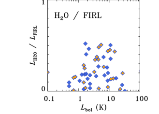
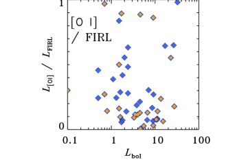
The fractions of cooling contributed by various species do not depend on the source parameters, i.e. its bolometric temperature and luminosity (see Figures B.9 and B.10 in the Appendix). The spread in the line luminosities divided by the total far-infrared line luminosities (FIRL) is substantial for all species, but clearly the largest for [O I]. We find, however, that the highest ratios of / FIRL are found for Class 0 sources, whereas the highest ratios of / FIRL are seen in Class I sources (see also Section 6.3).
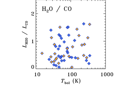
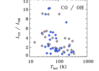
A better quantity to describe the far-infrared budget is the ratio of line luminosities of various species. As illustrated by Figure 2, the correlations between molecular species are very strong (), and only somewhat weaker between the molecules and [O I] (). As expected, the line ratios of those species cover a narrow range of values for the majority of the protostars (see Figure B.11 in the Appendix). Similar characteristics have been seen in the sample of protostars in Perseus. This uniformity implies that the entire sample can be treated as one, a consequence which will be utilized below.
5 Comparisons to models of shocks and photodissociation regions

Far-infrared line emission can be compared to shock models in order to derive the physical conditions of the medium and the properties of shock waves. A critical part of such comparisons is ensuring that the relevant species are emitted from the same location(s) in young stellar objects.
Karska et al. (2013) analyzed the patterns of spatially-resolved far-IR line emission toward 18 protostars from the WISH survey and concluded that (i) the emission follows the outflow directions as defined from CO 6-5 (Yıldız et al., 2012, 2015); (ii) high CO emission () seen in PACS is well-aligned with the emission in H2O, but differs with respect to [O I]. For the same protostars, Santangelo et al. (2012) and Kristensen et al. (2017b) show that the velocity-resolved profiles of CO 16-15 and H2O are almost identical, which strengthens the conclusion that the two species are connected.
Assuming the same origin of high- CO and H2O, Karska et al. (2014b) compared the observed line ratios of molecular species obtained for 22 protostars in Perseus (WILL survey) to the available stationary C- and J-type shock models in dark clouds fully-shielded from UV. In this way, the uncertainty in the distance and any large-scale environmental effects were minimised. The observed line ratios of various same-molecule pairs of H2O, CO, and OH lines cover a narrow range and agree with the models of -type stationary shocks propagating at (pre-shock) densities of 104-105 cm-3 (but not with the -type models, see top panel of Figure 8 in Karska et al. 2014b). However, the line ratios of H2O / CO, H2O / OH, and CO / OH lines are overestimated by stationary C- and J-shock models by 1-2 orders of magnitude with respect to observations. In order to reconcile these models and observations, Karska et al. (2014b) proposed that some H2O is photodissociated by FUV photons and thus its abundance is lowered with respect to OH and CO.
A number of low-mass sources show velocity-resolved emission from light (ionized) hydrides, e.g., CH, CH+, OH+ (Kristensen et al., 2013; Benz et al., 2016). The velocity structure is such that this emission originates in shocks. The observations were compared to models of fully dissociative shocks (Neufeld & Dalgarno, 1989): the molecular emission is consistent with the molecules reforming in the post-shock zone. The velocities required to dissociate the gas ( 50 km s-1) are inconsistent with the observed velocities ( 10 km s-1); instead, dissociation must come from elsewhere. Kristensen et al. (2013) proposed that the gas is dissociated by UV photons from the nearby accreting protostar, and that the observed signatures present direct evidence of UV irradiated shocks.
Further evidence comes from observations of H2O and high- CO. When the H2O abundance is inferred from comparison to high- CO 16–15 emission (Kristensen et al., 2017b), a total abundance of 10-6 is inferred. In warm shocked gas where K, all oxygen is expected to be driven into H2O (e.g. Bergin et al., 1998), and the total H2O abundance reaches 10-4. The observed decrease of two orders of magnitude implies that not all oxygen is driven into H2O. From a simple chemistry calculation, Kristensen et al. (2017b) showed that the abundance is consistent with a moderate UV field dissociating the H2O (), thus again demonstrating that UV irradiation likely dominates the chemistry whereas the shocks dominate the excitation.
While other solutions cannot be excluded, these would have to explain the multi-species line ratios, light (ionized) hydrides, and low absolute water abundance. One specific example of such a potential solution is non-stationary C-type shocks (Flower & Pineau des Forêts, 1999; Lesaffre et al., 2004b, a). Flower & Pineau des Forêts (2013) found satisfying non-stationary fits to PACS observations of CO, H2O, and OH in one protostar, NGC1333 IRAS 4B. However, the predictions of these models for the emission from ionised hydrides have not been investigated yet.
In the following sections, we measure the line ratios of H2O / CO, H2O / OH, and CO / OH lines for the entire sample presented here, and compare them with state-of-the-art models of stationary -type shocks illuminated by UV irradiation (Sect. 5.1). These models predict that a significant fraction of molecules are photodissociated, which increases the abundances of atomic and ionic species, particularly O and C+ and light ionized hydrides observed with HIFI (Kristensen et al., 2013). This in turn changes the emission spectrum of these atomic species. To test this hypothesis, we first update the observed molecular line ratios for the full sample, introducing the UV-irradiated shocks (§5.1), and comparing the atomic/ionic emission to stationary shock models (§5.2), then PDR models (§5.3) and finally irradiated shock models (§5.4). The reason for this approach is to isolate the effects of shocks and UV irradiation (PDR) separately, before combining them.
5.1 Molecular line ratios vs. models of UV-irradiated shocks
UV photons have an important impact on the chemical and thermal structure of a shock (Lesaffre et al., 2013; Melnick & Kaufman, 2015). The increase in the ionization fraction results in a tighter coupling between the ionized and neutral fluids and thus decreased coupling length. The decreased coupling length effectively means that the mechanical energy is deposited more rapidly into the gas, leading to higher peak temperatures for a given shock velocity than in fully-shielded shocks. In addition, the molecular and atomic abundances depend strongly on the strength of the radiation field and the gas density. As illustrated in Figure 1 of Melnick & Kaufman 2015, the pre-shock abundance of gas-phase atomic oxygen decreases as the density increases, because more oxygen is frozen out onto the dust grains when shielded from UV photons. At the same time, the oxygen abundance scales directly with the strength of the UV field, which photodissociates H2O. At pre-shock densities of 105 cm-3, the atomic oxygen abundance is to for UV fields of 0.1 to 10. H2O photodissociation also takes place in the post-shock gas, thus efficiently lowering its column-averaged abundance.
The physical conditions in these irradiated shocks depend very strongly on the charge balance, and as such it is crucial to keep accurate track of it through the shock. This is done in the shock models of Melnick & Kaufman (2015), where both the gas and grain charge balances are calculated at each step of the models, and the model results show that the shocks are stable.
Figure 10 show the observed line ratios of selected CO, H2O, and OH lines for the full sample of protostars and the results from stationary C-type shock models (Kaufman & Neufeld, 1996). There is a general trend for these shock models to overestimate the observed emission ratios, most clearly seen for the H2O / OH 84 m line ratio. The results obtained for the extended sample of sources presented here are consistent with the narrow ranges obtained for the sample of 22 protostars from Perseus (Karska et al., 2014b). Fully-shielded type shock models from Kaufman & Neufeld (1996) still overestimate the ratios when compared to the new observations. The same ratios calculated using shock models illuminated by UV radiation show a better agreement with the observations, for a range of shock parameters (Melnick & Kaufman, 2015, Kaufman in prep.).
The largest difference between the UV and non-UV shocks is seen in the ratio of the H2O - and OH 84.6 m lines, which is reduced in the new models by two orders of magnitude at pre-shock densities of 104 and 105 cm-3. The ratio of the H2O - and CO 16-15 lines is best reproduced by UV-irradiated -shocks at pre-shock densities of 104-105 cm-3, but the differences with respect to the models without UV are small. Similar conclusions hold also for other pairs of H2O/CO, H2O/OH, and CO/OH transitions (see Figure B.12), as well as for the ratios of total line luminosities in H2O / OH etc. (see Sec. 6.1.). Based on these line ratios and the observed chemical signatures (Kristensen et al., 2013), a scenario where emission arises in UV-irradiated stationary shocks seems very likely.
5.2 Atomic line fluxes vs. stationary shock models


Before comparing the observed atomic/ionic emission from O and C+ to irradiated shock models, it is instructive to first compare to stationary shock models without external UV radiation. To do so, we use the line fluxes from and -type shock models as presented in Flower & Pineau des Forêts (2015).
The model intensities in units of erg cm-2 s-1 sr-1 are translated to W cm-2 assuming that the emission entirely fills one spaxel in the PACS maps (1 sr ). A size of one spaxel is chosen despite the fact that PACS maps in the [O I] and [C II] lines often show emission extending to more than one spaxel (this work and Karska et al., 2013), because the actual emitting region observed by each spaxel is likely only a fraction of the spaxel size (i.e. the ‘filling factor’ is below unity). A possible underestimate of a factor of a few of the emitting region size does not affect the conclusions below given the orders of magnitude variations probed by the models and observations.
Comparison of absolute observed and model line fluxes of the [O I] 63 m and [C II] 158 m lines are shown in Figure 11 (top panel). The median observed [O I] flux, calculated for sources with emission spatially associated with YSOs, equals W cm-2 and falls between the predictions for the and type shock models for a wide range of shock velocities. The type shock model fluxes are insensitive to the shock velocities and equal 10-21 W cm-2 for a pre-shock density of cm-3 and 10-22 W cm-2 for a pre-shock density of cm-3, and are clearly inconsistent with the data.
The type shock model fluxes, on the other hand, fit even the brightest observed [O I] lines. A sharp increase from about 10-22 W cm-2 to 10-18 W cm-2 occurs when the shock becomes dissociative, at velocities of about 20 km s-1. Depending on the size of the emitting region, likely lower than the full spaxel area, the observations of all absolute line fluxes of [O I] can be reproduced with type shocks.
The observed fluxes and limits of the [C II] line at 158 m greatly exceed the model predictions for both and type shock models (Figure 11, bottom panel). Whenever the line is detected and associated with a YSO, the fluxes exceed 10-21 W cm-2, 4 orders of magnitude above the model shock fluxes and a factor of a few above the peak [C II] flux from the shocks, at velocities of about 30 km s-1. In the majority of the sources, however, the [C II] line is not detected and only an upper limit can be used for comparisons with the models. For those sources, the observed limit is consistent with both and type shocks.
5.3 Atomic line fluxes vs. models of photodissociation regions
As shown in the previous section, stationary C-type shock models do not reproduce [O I] and [C II] emission (when detected) by several orders of magnitude. Because [C II] is a well-known PDR tracer, it is instructive to check whether PDR models could explain the observed fluxes.
Producing [C II] emission in sufficient quantities requires hard UV photons with Å, likely originating in the vicinity of the protostar, in accretion flows at the accretion shock boundary layer and / or fast bow-shock (e.g. Spaans et al., 1995; van Kempen et al., 2009b). Models of photodissociation regions (PDRs, Tielens & Hollenbach, 1985) can be used to constrain the UV field and densities using the absolute intensities of atomic and ionic lines as well as molecules.
In our case, where most of the molecular emission and a part of the [O I] emission likely originates in shocks, comparisons to the absolute line intensities of [C II] are the most reliable measure of FUV alone. To better constrain the range of possible parameters, the ratio of [C II] and [O I] can be used, taking into account that a fraction of the [O I] emission may arise in from dissociative shocks associated with the jets. This ratio rapidly decreases with density, controlled mainly by [O I] with its high critical density of about cm-3, two orders of magnitude higher than for [C II] (Kaufman et al., 1999).
Figure 12 compares the observed [C II] / [O I] versus [C II] intensities for the subset of sources detected in [CII] with the PDR model predictions from Kaufman et al. (1999). The [C II] intensities are calculated assuming a size of one spaxel and shown only for sources where the [C II] emission is spatially associated with YSOs. The range of observed [C II] intensities is - erg cm-2 s-1 sr-1, whereas [C II] / [O I] ranges from -. The corresponding model densities range from to cm-3. The majority of the sources show a very similar incident UV field, about 102 G0 on scales of 1000 AU, with the exception of a more massive source, Serpens SMM1 (#66), which is in the 103 G0 regime. Independent high-angular resolution observations of free-free emission on scales of 1000 AU illustrate the presence of a strong UV field toward this source (Hull et al., 2016).
Possible contributions from shocks to the [O I] intensity would decrease both the densities and the UV field matching the observations (see Figure 12). For example, if 90% of [O I] flux comes from the shock, corresponding to an increase in the observed [C II] / [O I] by a factor of 10, the best fit densities are in the range - cm-3 and UV field of -102 G0. In fact, the spectrally resolved line profile of [O I] in a single outflow position in NGC1333 I4A, observed with SOFIA-GREAT by Kristensen et al. (2017a), resembles the high-velocity H2O and CO 16-15 profiles associated with the shocks observed with Herschel by Santangelo et al. (2014a). Similarly, [C II] profiles from HIFI obtained for a subsample of WISH sources reveal that the origin of emission may be shocks rather than a PDR (Kristensen et al., 2013; Benz et al., 2016). These factors suggest that the actual position of the PDR-only emission in these sources lies above and to the left of the observed fluxes, and so the densities and G0 values should be considered as upper limits.
Finally, we note that the diagnostic diagram from Figure 12 can be used to distinguish between PDRs associated with YSOs and clouds. For comparison with the local PDRs, two sources observed within a strong PDR in the W40 cloud (W40-MM26 and W40-MM27) are shown. Both of them are located in the low-density and high-UV regime that is very distinct from the other observed YSOs.

5.4 Atomic line fluxes vs. models of UV-irradiated shocks
Velocity-resolved spectra clearly suggests that [O I] and [C II] emission is associated with shocks (e.g. Benz et al., 2016; Kristensen et al., 2017a). The two previous sections (5.2 and 5.3) suggest that where stationary shocks fail is where PDR models succeed, i.e. in reproducing the atomic/ionic emission. This, in turn, suggests that for these species, shocks set the dynamics and PDRs set the chemistry and excitation.
The presence of UV photons increases the ionization fraction in the pre-shock gas, leading to gas that is hotter and more compressed for a given shock velocity than without FUV photons (Melnick & Kaufman, 2015). In addition, the pre-shock gas-phase abundances are altered and depend strongly on the strength of the radiation field and the gas density. For low values of the field, more O-bearing species are locked in ices, while for high fields they are desorbed into the gas phase. FUV radiation can also photodissociate H2O in the post-shock gas, and thus lower the column-averaged abundance of H2O and increase the O abundance (see Kristensen et al., 2017b, for an example calculation).
The abundances of atomic species are therefore expected to be significantly higher in UV illuminated shocks with respect to models of shielded shocks. Figure 13 shows that the fluxes of the [O I] and [C II] scale directly with the assumed UV fields and indeed are a few orders of magnitude above fully-shielded shock models (Flower & Pineau des Forêts, 2015). The critical density of [O I] at 63 m is cm-3, and so, in the models assuming pre-shock densities of cm-3, the absolute line flux quickly increases even at low pre-shock velocities ( km s-1). At higher shock velocities, the line flux changes are small, up to a factor of 2 between 10 and 20 km s-1. The maximum shock velocities, above which the shock becomes dissociative, are lower than in the fully-shielded shocks and equal about 30 km s-1 for and 20 km s-1 for (all values for pre-shock densities of cm-3). Similar trends are seen for the [C II] line, except that the initial rise is shallower due to the lower critical density of the line ( cm-3).
The model line fluxes predicted by UV illuminated shocks agree well with the detected [O I] line luminosities and non-detections of [C II] emission for the majority of the sources (Figure 11). The maximum value of the [O I] 63 m flux observed with PACS is W cm-2, setting the upper limit on UV fields of . The median [O I] flux is about two orders of magnitude lower, suggesting that the ‘filling factor’ of the UV illuminated shocks is below unity, similar to the conclusions drawn from the HIFI H2O line energetics (Mottram et al., 2014).
6 Discussion
6.1 Origin of far-IR emission in FUV-irradiated -shocks
Far-IR line emission observed with Herschel toward low-mass protostars is characterized by: (i) a spatially extended pattern along the outflow direction, in cases where emission is resolved, but not spatially coincident with the low- CO entrained gas (see Sec. 3.2, Karska et al. 2013, Nisini et al. 2015); (ii) broad molecular line profiles with velocities up to 50 km s-1 (Kristensen et al. 2012, 2017b, San José-García et al. 2013, Mottram et al. 2014, 2017); (iii) a universal CO rotational temperature of 300 K, independent of protostellar luminosity (see Sec. 4.1, Manoj et al. 2013, Karska et al. 2013, Green et al. 2013, Matuszak et al. 2015, Jiménez-Donaire et al. 2017); (iv) an overall cooling budget in far-IR lines similar to predictions of stationary C type shocks (see Sect. 4.2, Karska et al. 2013, Lee et al. 2014a). Altogether, these characteristics suggest that the bulk of emission arises either in outflow cavity shocks (e.g. Mottram et al., 2014) or in the molecular disk wind (Panoglou et al., 2012; Yvart et al., 2016).
Comparisons of specific line fluxes with shock models offer an opportunity to further determine the pre- and post-shock density of the gas, as well as the shock parameters themselves (its velocity and type, dependent on the ionization fraction and the presence of a magnetic field). However, many different shock models reproduce the observed line fluxes of certain far-IR species for individual targets, resulting in a broad range of the derived shock parameters (e.g. Santangelo et al. 2013, Dionatos et al. 2013, Benedettini et al. 2012; Busquet et al. 2014; Lee et al. 2014a). A more homogeneous comparison of 20 protostars in Perseus with stationary - and - type shock models from Kaufman & Neufeld (1996) and Flower & Pineau des Forêts (2010) illustrated that in fact none of those models can reproduce line ratios of different species (e.g. H2O / CO, H2O / OH, and CO / OH, Karska et al. 2014b). Additionally, stationary shock models alone cannot reproduce the observed CO ladders of Class 0 / I protostars (van Kempen et al., 2010b; Visser et al., 2012).
In Sec. 5, we showed the model predictions of far-IR spectra for shocks propagating at pre-shock densities of 103-105 cm-3 and irradiated by UV fields of G0 equal 0.1, 1 and 10 (Melnick & Kaufman, 2015, Kaufman in prep.). Line ratios such as H2O / OH 84 m generally decrease in the presence of UV photons that photodissociate H2O into OH and O. Stationary -type shocks also clearly cannot account for the emission in O and C+ (Fig. 11), but separating the emission from the shock and from the possible PDR is non-trivial with unresolved line profiles. The order of magnitude estimates of UV fields with PDR models require assumptions about the contribution of the jet in the [O I] emission (Fig. 12).

The shock models illuminated by FUV are in agreement with selected line ratios presented in Karska et al. (2014b). A comparison involving all observed transitions is shown in Figure 14. The total far-infrared line luminosities in H2O, CO, and OH were calculated in Sec. 4.2, and their sum is indicated as . The total line luminosities from the models are calculated using the transitions accessible with PACS: the H2O lines located in the 56 - 94.7 m and 108.0 - 180.5 m ranges, the CO lines with and , and 8 OH doublets (at 65, 71, 79, 84, 119, and 163 m). The observed ratios of H2O / CO, H2O / OH, CO / OH, and H2O / [O I] show a Gaussian distribution and therefore are representative for the entire sample (Figure B.8).
The trends in the model line ratios result from the amount of oxygen available in the gas phase and the length scale over which the temperature and abundances are elevated behind the shock. The abundance of oxygen scales almost linearly with the logarithm of / (Melnick & Kaufman, 2015, Kaufman in prep.), and thus, for stronger UV fields and for a given pre-shock density, the abundance of H2O is larger (see the trends in the H2O / CO ratio). Additionally, the length scale is inversely proportional to the square root of pre-shock density () at the assumed , so for larger pre-shock densities, the shock-averaged column of H2O decreases (see Fig. 2 in Melnick & Kaufman, 2015).
Since H2O is efficiently formed at K by hydrogenation of OH (Bergin et al., 1998), the peak abundance of H2O behind the shock corresponds to the drop in the OH abundance. Further out from the shock, H2O is photodissociated by the UV photons, and the higher , the lower H2O / OH ratio (see Fig. 14). The increase in OH abundances with increasing UV field also explains the decrease of the CO / OH ratio for . The trends in H2O / [O I] resembles that of H2O / OH, except that at densities as low as 103 cm-3 both H2O and OH are efficiently photodissociated, and the ratio of the H2O / [O I] for high drops to . The balance between O, OH, and H2O depends also on the H/H2 ratio and temperature, which has to be considered.
The ratios of total line luminosities calculated from the models and from the observations show a good agreement with the observed range of pre-shock densities, 104-105 cm-3. The H2O / OH and H2O / [O I] ratios are also explained by the pre-shock densities of 103 cm-3, but CO is not well-reproduced at these lower densities. The UV fields considered here ( of 0.1 and 10) and illuminating shocks produce model line ratios in the same range as the observed ratios.
6.2 Impact of UV irradiation on the CO ladder
The shape of the CO ladder in the far-IR is universal across Class 0 and I protostars (Sec. 4.1, e.g. Manoj et al. 2013; Karska et al. 2013; Green et al. 2013; Lindberg et al. 2014) as well as across several orders of magnitudes in luminosity (Karska et al., 2014a; Matuszak et al., 2015; Mashian et al., 2015). In the energy range covered by =14-24, the CO rotational diagram typically consists of a single linear component, corresponding to the temperature of K with a standard deviation % (the so-called ‘warm’ component). Out of 90 sources from our sample, 59 protostars show the ‘warm’ component. Out of those protostars, 21 sources (more than 1/3) show an additional linear component corresponding to the temperature of K with a standard deviation % (the so-called ‘hot’ component).
Several interpretations have been proposed to explain the shape of the CO ladder in low-mass protostars. Visser et al. (2012) modeled the shape of the PACS CO ladder in three objects with a combination of passively heated envelope, UV-heated cavity walls and small-scale -type shocks. The bulk of emission was attributed to a PDR and shocks, with a tentative trend of increasing role of UV photons for more evolved sources. Indeed, more recent models confirm that the 300 K component in CO ladders can be well-reproduced even by pure UV heating of the outflow cavities (Lee et al., 2014b, 2015). Observationally, the presence of UV photons is supported by extended emission in 13CO =6-5, which delineates the outflow cavity walls in nearby protostars (Yıldız et al., 2012, 2015). Yet, the CO transitions in a broad range of levels cannot be explained by UV heating alone.
Neufeld (2012) reproduced the curved shape of the rotational diagram using a single component fit, assuming a subthermal excitation of CO (densities of 103 cm-3 and temperatures above 1000 K). Apart from the the sources with the highest- CO transitions, successful fits of this kind were obtained for most of the protostars observed in the HOPS and DIGIT key programs (Manoj et al., 2013; Green et al., 2013). An alternative approach considers the ladder as the combination of two distinct physical components, with densities above 104-105 cm-3 (e.g. Karska et al., 2013). Flower & Pineau des Forêts (2013) are associating those two components with (‘warm’ component) and (‘hot’ component) shocks, while Neufeld et al. (2014) explain them as a combination of shocks with different velocities. A comprehensive analysis of the high- CO line profiles from HIFI associates two distinct velocity components with two excitation components, corresponding to the warm and hot PACS components (Kristensen et al., 2017b).

As shown in previous section, the observed far-IR line fluxes are mostly produced in type shocks, likely ubiquitous in the regions of outflow-envelope interactions. At the same time, there is a strong spatial and kinematic association of high CO emission with H2O (Kristensen et al., 2012, 2017b; Yıldız et al., 2013; Mottram et al., 2014, 2017). The required pre-shock densities are of order cm-3, translating to densities cm-3 adopting a compression factor of in these shocks (see Sec. 5.3 in Karska et al., 2013).
The only feasible alternative to -type shocks are molecular disk winds, where excitation of H2O and high- CO is caused by similar processes as in molecular shocks (Panoglou et al., 2012; Yvart et al., 2016). The wind models match the velocity-resolved H2O 557 GHz and higher-excited line profiles very well, but predictions for high- CO lines such as presented here are not yet available.
Fully-shielded, stationary shock models cannot reproduce at once the entire CO ladder (van Kempen et al., 2010b; Visser et al., 2012). It is therefore interesting to explore the effect of UV irradiation of shocks on the shape of those CO ladders. Figure 15 compares two C shock models calculated for UV fields equal of 0.1 and 10 (Melnick & Kaufman, 2015, Kaufman in prep.), for a single pre-shock density of 105 cm-3 and a shock velocity of km s-1. The datapoints correspond to the transitions located in the PACS range up to (at 72.8 m).
Two linear fits to the diagrams give rotational temperatures of 340 K and K for the of 0.1 and temperatures of K and K for the of 10. Clearly, in the presence of very low UV fields (=0.1), the CO rotational temperature of the ‘warm’ component is in good agreement with observations (see Fig. 6). The temperature of the ‘hot’ component is within the observed ranges as well. Similarly, the model with of 10 shows the ‘hot’ component characterized by a higher, but still consistent with observations, temperature of about K. The ‘warm’ component temperature here is at the higher end of the observations (Fig. 6). A full grid of models is required to assess whether a single model can account for the entire CO ladder.
| Class 0 | Class I | |||
|---|---|---|---|---|
| mean | median | mean | median | |
| /) | -3.37 | -3.21 | -3.66 | -3.56 |
| /) | -0.47 | -0.35 | -0.66 | -0.53 |
| /) | -3.60 | -3.50 | -3.73 | -3.57 |
| /) | -0.83 | -0.71 | -0.85 | -0.75 |
| /) | -3.97 | -3.86 | -3.85 | -3.82 |
| /) | -1.18 | -0.98 | -0.90 | -0.81 |
| /) | -3.53 | -3.55 | -3.52 | -3.65 |
| /) | -0.81 | -0.75 | -0.60 | -0.55 |
| /) | -0.30 | -0.33 | -0.19 | -0.13 |
| /) | 0.42 | 0.32 | 0.07 | 0.07 |
| /) | 0.68 | 0.68 | 0.26 | 0.23 |
| /) | -0.003 | 0.04 | -0.23 | -0.24 |
Observationally, the high-temperature component at CO ladders is detected in 21 sources (Sec. 4.1.) and can be associated with a specific Gaussian component in the velocity-resolved line profiles from HIFI (Kristensen et al., 2017b). The fraction of emission in this particular profile component compared to the rest of the emission, associated with the bulk outflow, is 20% (hot component) and 80% (warm component) of the total line emission. Thus, in agreement with the fractions contributed by the ‘warm’ and ‘hot’ components seen on CO rotational diagrams. The absence of the hot component in the majority of the sources is due to low S/N rather than the presence or lack of the UV radiation.
In summary, preliminary models of -shocks irradiated by FUV qualitatively explain the decrease in the amount of H2O relative to e.g. CO and OH, and perhaps the excitation of the highest- CO lines. The average values of UV fields that match our observations are of the order of 0.1-10 times the interstellar radiation field. The order-of-magnitude estimates of UV fields presented here are in agreement with a recent survey of ionized hydrides, where UV fields determined in low-mass protostars are 2-400 times the interstellar value (Benz et al., 2016).
The next step is to calculate a full grid of shock models to verify that the conclusions reached here, based on just a few model calculations, are robust. This will further assist in demonstrating that the ‘warm’ component is reproduced by a large range of shock conditions.
6.3 Evolution of the far-infrared line emission
The changes in physical processes and conditions as the protostar evolves from Class 0 to Class I should be reflected in the cooling by various atomic and molecular species and the total far-IR gas cooling budget.
As demonstrated in Figure 8 (§4.2.2), the distributions of line luminosities over for each far-IR species are similar between Class 0 and Class I protostars except for CO. The overall line cooling is dominated by CO and H2O, followed by [O I] and OH, consistent with previous surveys (Karska et al., 2013). The spread in line luminosities – both absolute and divided by – is significant for both Class 0 and I protostars (see Table 5). In order to track the evolutionary changes, we therefore normalize the line cooling in each species with the total line luminosity in the far-IR, defined by Nisini et al. 2002 as . As a result, the spread of values within each class of objects decreases (see Table 5).

Figure 16 illustrates how line luminosities of CO, H2O, [OI], and OH change between the Class 0 and I stages. The dominant cooling in the CO lines in Class 0 protostars decreases by a factor of 2.3. On the other hand, the line cooling in H2O, [O I], and OH do not change significantly. This is confirmed by two-sample Kolmogorov-Smirnov (K-S) tests comparing the ratios of line luminosities over for Class 0 and I sources. Only the ratio shows a statistically significant difference between these evolutionary stages (6% chance of being drawn from the same distribution). Thus, the less evolved sources emit more copiously in CO, which - unlike H2O - is not easily destroyed by photodissociation (Kristensen et al., 2017b).
The redistribution of cooling in molecular and atomic channels does not strongly affect the total far-IR line cooling (), which decreases only by a factor of 1.2, from L⊙ in Class 0 to L⊙ in Class I. shows no significant correlation with , but clearly correlates with (Figure 17), consistent with previous studies (Nisini et al., 2002; Karska et al., 2013). The difference between Class 0 and I objects is confirmed by K-S tests with probability of less than 1% that the are drawn from the same distribution. Removal of the - dependence, i.e. the quantity /, would allow us to isolate a very weak relation with the bolometric temperature, but the K-S test fails due to the large spread of values. This large spread of / values on top of the decrease in total far-IR cooling with time shows that the processes responsible for the line cooling likely depend on object-to-object characteristics e.g. local environment and the amount of UV radiation illuminating the shocked gas.


An almost linear relation between the total far-IR cooling and bolometric luminosity ( ) was first reported based on ISO data and interpreted as a consequence of a wind/jet interactions with the surroundings, driven by protostellar accretion and subsequent ejection (Giannini et al., 2001; Nisini et al., 2002). In fact, can be used as a direct measure of mechanical luminosity deposited by the jet/outflow (Maret et al., 2009). For km s-1 shocks propagating into the ambient density of cm-3 and illuminated by UV fields (§5), the mass loss rates corresponding to the observed line cooling can be calculated following Equation 2 from Maret et al. 2009:
| (1) |
Adopting and , where is the fraction of shock mechanical energy translated into excitation, and is the fraction of cooling due to far-IR transitions of CO, H2O, [O I], and OH for the best-fitting shock model (the remaining cooling contributed by H2), we find mass-loss rates of, M⊙ yr-1 for Class 0 protostars and M⊙ yr-1 for Class I protostars.
Mass loss rates of the order of M⊙ yr-1 are consistent with the rates calculated using the fully-sampled maps of outflows from Class 0 protostars obtained in the [O I] line at 63 m (Nisini et al., 2015; Mottram et al., 2017). Using such maps, the [O I] jet tangential velocity and its length projected onto the plane of the sky can be determined, but similar observations are not available for a statistical sample of protostars. In fact, the sources mapped as part of this project are well-known for their bright outflows and the derived mass loss rates from the [O I] line are likely at the higher end of the expected values. Thus, the total far-IR line cooling coupled with shock models seems to be a valid method of determining the mass loss rates for protostars and more reliable than the [O I] alone.
Mottram et al. (2017) found that the ratio of mass in the entrained outflow to envelope mass vary between 0.1 and 10%, peaking at about 1% for both Class 0 and I protostars in the WILL sample. In this context, similar values of the mass loss rates found here are generally in agreement with their argument in favor of an approximately constant entrainment efficiency per unit length during Class 0/I. The relatively low values of mass loss rate of M⊙ yr-1 suggest that the the core-to-star formation efficiency is likely higher than 50%.
7 Summary and conclusions
Herschel / PACS observations in the surroundings of low-mass protostars characterize the cooling of the gas at the earliest stages of star formation. A combination of atomic and molecular tracers provides hints about the underlying heating processes that produce the hot gas observed here. The bulk of molecular emission traces non-dissociative shocks occurring in the outflows. UV photons influence the chemistry in those shocks, altering the abundances of key cooling species. The main conclusions, addressing each of the questions raised in the introduction, are the following:
-
1.
Rich far-IR line emission of H2O, CO, OH and [O I] is detected in % of the targeted sources, allowing the statistical and unbiased analysis of such emission in the largest sample of protostars so far.
-
2.
Lines of H2O and CO are strongly correlated and a weaker relation is found between the molecular species and [O I].
-
3.
56% of sources show compact atomic and molecular emission on AU scales. The remaining sources show extended emission on at least AU scales covered within our survey, mostly in [O I]. 25 sources (28%) show clear extended emission in molecular tracers. Among 17 sources which show extended emission in both CO and H2O lines, 11 are Class 0 objects. At the same time, only 5 out of 13 sources with extended emission in [O I] are Class 0 objects. The emission is extended along the direction of the outflow seen in the CO 3-2 maps of the regions, but not emitting from the same gas (Mottram et al., 2017).
-
4.
In 10 sources for which the [O I] shows extended emission on AU scales, a high-velocity ( km s-1) component emerges in the line profiles. Thus, [O I] is closely related to the atomic jet, as suggested by previous studies (e.g. Nisini et al., 2015). However, the bulk of the [OI] emission is spectrally unresolved.
-
5.
Analysis of the molecular excitation using rotational diagrams gives a median 320 K for CO (1800 K), 130 K for H2O (700 K), and 85 K for OH. Additionally, emission from hot CO and H2O is detected for 24% and 10% of sources, respectively, covering a broad range of rotational temperatures with a median at K for CO and at K for H2O. Densities cm-3 and kinetic temperatures K are required to explain the excitation.
-
6.
The far-IR line cooling budget in Class 0 sources is dominated by CO (40%), followed by H2O and [O I] (%). In Class I sources, the cooling is dominated by [O I] (%), and CO and H2O (%). The fractions of cooling contributed by various species do not depend strongly on bolometric luminosity.
-
7.
Line flux ratios of different molecules (e.g., H2O/OH, H2O/CO) suggest that the bulk of emission does not arise in standard -type shocks. These ratios, along with observations of light hydrides (Kristensen et al., 2013; Benz et al., 2016) and low H2O absolute abundances (Kristensen et al., 2017b) instead point to emission originating in UV-irradiated shocks.
-
8.
Models of UV-irradiated shocks successfully reproduce molecular line ratios for pre-shock densities of cm-3 and of . More detailed modeling is required to match emission from individual sources to specific shock models.
-
9.
Comparisons of the atomic line fluxes with stationary shock models show that the observations cannot be reproduced with non-dissociative -shocks. While the [O I] fluxes could be mitigated with an additional -shock component, the [CII] line detected in 10 sources requires UV irradiation. Comparisons to models of photodissociation regions allow us to estimate the strength of the UV fields , assuming that 90% of the [O I] emission arises in the dissociative jet shocks.
-
10.
New models of -shocks illuminated by UV can reproduce the absolute line fluxes of [O I] and non-detections of [C II].
-
11.
Far-IR line cooling does not change significantly from the Class 0 to Class I stage. As a proxy of the mechanical energy deposited by the jet/outflow, it allows the calculation of mass loss rates of M⊙ yr-1. These relatively low values suggest that the core-to-star formation efficiency is likely higher than 50%. The nearly constant value obtained for Class 0 and I sources implies that the accretion/ejection and associated feedback mechanisms are comparable across the protostellar evolution.
We wish to thank the entire WISH, DIGIT, and WILL teams for stimulating discussions and the common effort in analysing and interpreting the Herschel observations. AK acknowledges support from the Foundation for Polish Science (FNP) and the Polish National Science Center grants 2013/11/N/ST9/00400 and 2016/21/D/ST9/01098. Sub-millimeter astronomy in Copenhagen is supported by the European Research Council (ERC) under the European Union’s Horizon 2020 research and innovation programme (grant agreement No 646908) through ERC Consolidator Grant “S4F”. Herschel was an ESA space observatory with science instruments provided by the European-led Principal Investigator consortia and with important participation from NASA. Astrochemistry in Leiden is supported by the Netherlands Research School for Astronomy (NOVA), by a Royal Netherlands Academy of Arts and Sciences (KNAW) professor prize, by a Spinoza grant and grant 614.001.008 from the Netherlands Organisation for Scientific Research (NWO). JCM acknowledges support from the European Research Council under the European Community’s Horizon 2020 framework program (2014-2020) via the ERC Consolidator grant ‘From Cloud to Star Formation (CSF)’ (project number 648505). Support for this work, part of the Herschel Open Time Key Project Program, was provided by NASA through an award issued by the Jet Propulsion Laboratory, California Institute of Technology. NS acknowledges the support from the Polish National Science Center grant 2014/15/B/ST9/02111. Research conducted within the scope of the HECOLS International Associated Laboratory, supported in part by the Polish NCN grant DEC-2013/08/M/ST9/00664.
References
- André et al. (2010) André, P., Men’shchikov, A., Bontemps, S., et al. 2010, A&A, 518, L102
- Arce et al. (2007) Arce, H. G., Shepherd, D., Gueth, F., et al. 2007, Protostars and Planets V, University of Arizona Press (2006), eds. B. Reipurth, D. Jewitt, and K. Keil, 245
- Bachiller et al. (2001) Bachiller, R., Pérez Gutiérrez, M., Kumar, M. S. N., & Tafalla, M. 2001, A&A, 372, 899
- Bachiller & Tafalla (1999) Bachiller, R., & Tafalla, M. 1999, in NATO ASIC Proc. 540: The Origin of Stars and Planetary Systems, Dordrecht; Boston: Kluwer Academic Publishers, eds. C.J. Lada, N. Kylafis, 227
- Benedettini et al. (2012) Benedettini, M., Busquet, G., Lefloch, B., et al. 2012, A&A, 539, L3
- Benz et al. (2016) Benz, A. O., Bruderer, S., van Dishoeck, E. F., et al. 2016, A&A, 590, A105
- Bergin et al. (1998) Bergin, E. A., Neufeld, D. A., & Melnick, G. J. 1998, ApJ, 499, 777
- Busquet et al. (2014) Busquet, G., Lefloch, B., Benedettini, M., et al. 2014, A&A, 561, A120
- Carney et al. (2016) Carney, M. T., Yıldız, U. A., Mottram, J. C., et al. 2016, A&A, 586, A44
- Clegg et al. (1996) Clegg, P. E., Ade, P. A. R., Armand, C., et al. 1996, A&A, 315, L38
- de Graauw et al. (2010) de Graauw, T., Helmich, F. P., Phillips, T. G., et al. 2010, A&A, 518, L6
- Dionatos & Güdel (2017) Dionatos, O., & Güdel, M. 2017, A&A, 597, A64
- Dionatos et al. (2013) Dionatos, O., Jørgensen, J. K., Green, J. D., et al. 2013, A&A, 558, A88
- Dionatos et al. (2014) Dionatos, O., Jørgensen, J. K., Teixeira, P. S., Güdel, M., & Bergin, E. 2014, A&A, 563, A28
- Drozdovskaya et al. (2015) Drozdovskaya, M. N., Walsh, C., Visser, R., Harsono, D., & van Dishoeck, E. F. 2015, MNRAS, 451, 3836
- Dunham et al. (2014) Dunham, M. M., Stutz, A. M., Allen, L. E., et al. 2014, Protostars and Planets VI, University of Arizona Press (2014), eds. H. Beuther, R. Klessen, C. Dullemond, Th. Henning, arXiv:1401.1809
- Dunham et al. (2015) Dunham, M. M., Allen, L. E., Evans, II, N. J., et al. 2015, ApJS, 220, 11
- Enoch et al. (2009) Enoch, M. L., Evans, II, N. J., Sargent, A. I., & Glenn, J. 2009, ApJ, 692, 973
- Evans et al. (2009) Evans, II, N. J., Dunham, M. M., Jørgensen, J. K., et al. 2009, ApJS, 181, 321
- Flower & Pineau des Forêts (1999) Flower, D. R., & Pineau des Forêts, G. 1999, MNRAS, 308, 271
- Flower & Pineau des Forêts (2010) —. 2010, MNRAS, 406, 1745
- Flower & Pineau des Forêts (2013) —. 2013, MNRAS, 436, 2143
- Flower & Pineau des Forêts (2015) —. 2015, A&A, 578, A63
- Frank et al. (2014) Frank, A., Ray, T. P., Cabrit, S., et al. 2014, Protostars and Planets VI, University of Arizona Press (2014), eds. H. Beuther, R. Klessen, C. Dullemond, Th. Henning, arXiv:1402.3553
- Giannini et al. (2001) Giannini, T., Nisini, B., & Lorenzetti, D. 2001, ApJ, 555, 40
- Goicoechea et al. (2012) Goicoechea, J. R., Cernicharo, J., Karska, A., et al. 2012, A&A, 548, A77
- Goldsmith & Langer (1978) Goldsmith, P. F., & Langer, W. D. 1978, ApJ, 222, 881
- Green et al. (2013) Green, J. D., Evans, II, N. J., Jørgensen, J. K., et al. 2013, ApJ, 770, 123
- Green et al. (2016) Green, J. D., Yang, Y.-L., Evans, II, N. J., et al. 2016, AJ, 151, 75
- Herczeg et al. (2012) Herczeg, G. J., Karska, A., Bruderer, S., et al. 2012, A&A, 540, A84
- Heyminck et al. (2012) Heyminck, S., Graf, U. U., Güsten, R., et al. 2012, A&A, 542, L1
- Hollenbach et al. (1989) Hollenbach, D. J., Chernoff, D. F., & McKee, C. F. 1989, in ESA Special Publication, Vol. 290, Infrared Spectroscopy in Astronomy, ed. E. Böhm-Vitense, 245–258
- Hull et al. (2016) Hull, C. L. H., Girart, J. M., Kristensen, L. E., et al. 2016, ApJ, 823, L27
- Je et al. (2015) Je, H., Lee, J.-E., Lee, S., Green, J. D., & Evans, II, N. J. 2015, ApJS, 217, 6
- Jiménez-Donaire et al. (2017) Jiménez-Donaire, M. J., Meeus, G., Karska, A., et al. 2017, A&A, 605, A62
- Karska et al. (2013) Karska, A., Herczeg, G. J., van Dishoeck, E. F., et al. 2013, A&A, 552, A141
- Karska et al. (2014a) Karska, A., Herpin, F., Bruderer, S., et al. 2014a, A&A, 562, A45
- Karska et al. (2014b) Karska, A., Kristensen, L. E., van Dishoeck, E. F., et al. 2014b, A&A, 572, A9
- Kaufman & Neufeld (1996) Kaufman, M. J., & Neufeld, D. A. 1996, ApJ, 456, 611
- Kaufman et al. (1999) Kaufman, M. J., Wolfire, M. G., Hollenbach, D. J., & Luhman, M. L. 1999, ApJ, 527, 795
- Kessler et al. (1996) Kessler, M. F., Steinz, J. A., Anderegg, M. E., et al. 1996, A&A, 315, L27
- Kristensen et al. (2017a) Kristensen, L. E., Gusdorf, A., Mottram, J. C., et al. 2017a, A&A, 601, L4
- Kristensen et al. (2013) Kristensen, L. E., van Dishoeck, E. F., Benz, A. O., et al. 2013, A&A, 557, A23
- Kristensen et al. (2012) Kristensen, L. E., van Dishoeck, E. F., Bergin, E. A., et al. 2012, A&A, 542, A8
- Kristensen et al. (2017b) Kristensen, L. E., van Dishoeck, E. F., Mottram, J. C., et al. 2017b, A&A, 605, A93
- Lee et al. (2013) Lee, J., Lee, J.-E., Lee, S., et al. 2013, ApJS, 209, 4
- Lee et al. (2014a) Lee, J.-E., Lee, J., Lee, S., Evans, II, N. J., & Green, J. D. 2014a, ApJS, 214, 21
- Lee et al. (2015) Lee, S., Lee, J.-E., & Bergin, E. A. 2015, ApJS, 217, 30
- Lee et al. (2014b) Lee, S., Lee, J.-E., Bergin, E. A., & Park, Y.-S. 2014b, ApJS, 213, 33
- Lefloch et al. (2012) Lefloch, B., Cabrit, S., Busquet, G., et al. 2012, ApJ, 757, L25
- Lesaffre et al. (2004a) Lesaffre, P., Chièze, J.-P., Cabrit, S., & Pineau des Forêts, G. 2004a, A&A, 427, 147
- Lesaffre et al. (2004b) —. 2004b, A&A, 427, 157
- Lesaffre et al. (2013) Lesaffre, P., Pineau des Forêts, G., Godard, B., et al. 2013, A&A, 550, A106
- Leurini et al. (2015) Leurini, S., Wyrowski, F., Wiesemeyer, H., et al. 2015, A&A, 584, A70
- Lindberg et al. (2014) Lindberg, J. E., Jørgensen, J. K., Green, J. D., et al. 2014, A&A, 565, A29
- Manoj et al. (2013) Manoj, P., Watson, D. M., Neufeld, D. A., et al. 2013, ApJ, 763, 83
- Manoj et al. (2016) Manoj, P., Green, J. D., Megeath, S. T., et al. 2016, ApJ, 831, 69
- Maret et al. (2009) Maret, S., Bergin, E. A., Neufeld, D. A., et al. 2009, ApJ, 698, 1244
- Mashian et al. (2015) Mashian, N., Sturm, E., Sternberg, A., et al. 2015, ApJ, 802, 81
- Matuszak et al. (2015) Matuszak, M., Karska, A., Kristensen, L. E., et al. 2015, A&A, 578, A20
- Maury et al. (2011) Maury, A. J., André, P., Men’shchikov, A., Könyves, V., & Bontemps, S. 2011, A&A, 535, A77
- Melnick & Kaufman (2015) Melnick, G. J., & Kaufman, M. J. 2015, ApJ, 806, 227
- Mottram et al. (2014) Mottram, J. C., Kristensen, L. E., van Dishoeck, E. F., et al. 2014, A&A, 572, A21
- Mottram et al. (2017) Mottram, J. C., van Dishoeck, E. F., Kristensen, L. E., et al. 2017, A&A, 600, A99
- Murillo et al. (2016) Murillo, N. M., van Dishoeck, E. F., Tobin, J. J., & Fedele, D. 2016, A&A, 592, A56
- Neufeld (2012) Neufeld, D. A. 2012, ApJ, 749, 125
- Neufeld & Dalgarno (1989) Neufeld, D. A., & Dalgarno, A. 1989, ApJ, 344, 251
- Neufeld et al. (2014) Neufeld, D. A., Gusdorf, A., Güsten, R., et al. 2014, ApJ, 781, 102
- Nisini et al. (2002) Nisini, B., Giannini, T., & Lorenzetti, D. 2002, ApJ, 574, 246
- Nisini et al. (2010) Nisini, B., Benedettini, M., Codella, C., et al. 2010, A&A, 518, L120
- Nisini et al. (2015) Nisini, B., Santangelo, G., Giannini, T., et al. 2015, ApJ, 801, 121
- Offner et al. (2009) Offner, S. S. R., Klein, R. I., McKee, C. F., & Krumholz, M. R. 2009, ApJ, 703, 131
- Ortiz-León et al. (2017) Ortiz-León, G. N., Dzib, S. A., Kounkel, M. A., et al. 2017, ApJ, 834, 143
- Ott (2010) Ott, S. 2010, in Astronomical Society of the Pacific Conference Series, Vol. 434, Astronomical Data Analysis Software and Systems XIX, ed. Y. Mizumoto, K.-I. Morita, & M. Ohishi, 139
- Panoglou et al. (2012) Panoglou, D., Cabrit, S., Pineau Des Forêts, G., et al. 2012, A&A, 538, A2
- Pilbratt et al. (2010) Pilbratt, G. L., Riedinger, J. R., Passvogel, T., et al. 2010, A&A, 518, L1
- Podio et al. (2012) Podio, L., Kamp, I., Flower, D., et al. 2012, A&A, 545, A44
- Poglitsch et al. (2010) Poglitsch, A., Waelkens, C., Geis, N., et al. 2010, A&A, 518, L2
- Riviere-Marichalar et al. (2016) Riviere-Marichalar, P., Merín, B., Kamp, I., Eiroa, C., & Montesinos, B. 2016, A&A, 594, A59
- San José-García et al. (2013) San José-García, I., Mottram, J. C., Kristensen, L. E., et al. 2013, A&A, 553, A125
- Santangelo et al. (2012) Santangelo, G., Nisini, B., Giannini, T., et al. 2012, A&A, 538, A45
- Santangelo et al. (2013) Santangelo, G., Nisini, B., Antoniucci, S., et al. 2013, A&A, 557, A22
- Santangelo et al. (2014a) Santangelo, G., Antoniucci, S., Nisini, B., et al. 2014a, A&A, 569, L8
- Santangelo et al. (2014b) Santangelo, G., Nisini, B., Codella, C., et al. 2014b, A&A, 568, A125
- Spaans et al. (1995) Spaans, M., Hogerheijde, M. R., Mundy, L. G., & van Dishoeck, E. F. 1995, ApJ, 455, L167
- Spezzi et al. (2013) Spezzi, L., Cox, N. L. J., Prusti, T., et al. 2013, A&A, 555, A71
- Sturm et al. (2013) Sturm, B., Bouwman, J., Henning, T., et al. 2013, A&A, 553, A5
- Stutz et al. (2013) Stutz, A. M., Tobin, J. J., Stanke, T., et al. 2013, ApJ, 767, 36
- Tielens & Hollenbach (1985) Tielens, A. G. G. M., & Hollenbach, D. 1985, ApJ, 291, 722
- Tobin et al. (2016a) Tobin, J. J., Stutz, A. M., Manoj, P., et al. 2016a, ApJ, 831, 36
- Tobin et al. (2016b) Tobin, J. J., Looney, L. W., Li, Z.-Y., et al. 2016b, ApJ, 818, 73
- van der Marel et al. (2013) van der Marel, N., Kristensen, L. E., Visser, R., et al. 2013, A&A, 556, A76
- van Dishoeck et al. (2011) van Dishoeck, E. F., Kristensen, L. E., Benz, A. O., et al. 2011, PASP, 123, 138
- van Kempen et al. (2009a) van Kempen, T. A., van Dishoeck, E. F., Salter, D. M., et al. 2009a, A&A, 498, 167
- van Kempen et al. (2009b) van Kempen, T. A., van Dishoeck, E. F., Güsten, R., et al. 2009b, A&A, 501, 633
- van Kempen et al. (2010a) van Kempen, T. A., Green, J. D., Evans, N. J., et al. 2010a, A&A, 518, L128
- van Kempen et al. (2010b) van Kempen, T. A., Kristensen, L. E., Herczeg, G. J., et al. 2010b, A&A, 518, L121
- Visser et al. (2012) Visser, R., Kristensen, L. E., Bruderer, S., et al. 2012, A&A, 537, A55
- Wampfler et al. (2011) Wampfler, S. F., Bruderer, S., Kristensen, L. E., et al. 2011, A&A, 531, L16
- Wampfler et al. (2013) Wampfler, S. F., Bruderer, S., Karska, A., et al. 2013, A&A, 552, A56
- Winston et al. (2012) Winston, E., Cox, N. L. J., Prusti, T., et al. 2012, A&A, 545, A145
- Yang et al. (2017) Yang, Y.-L., Evans, II, N. J., Green, J. D., Dunham, M. M., & Jørgensen, J. K. 2017, ApJ, 835, 259
- Yıldız et al. (2012) Yıldız, U. A., Kristensen, L. E., van Dishoeck, E. F., et al. 2012, A&A, 542, A86
- Yıldız et al. (2013) —. 2013, A&A, 556, A89
- Yıldız et al. (2015) —. 2015, A&A, 576, A109
- Yvart et al. (2016) Yvart, W., Cabrit, S., Pineau des Forêts, G., & Ferreira, J. 2016, A&A, 585, A74
Appendix A Rotational diagrams
Figures A.1 and A.2 show CO rotational diagrams for the WILL sources. Separate linear fits are done to the transitions located in the ‘warm’ and ‘hot’ components, the same as used in Karska et al. (2013) and Green et al. (2013). Figures A.3 and A.4 show H2O rotational diagrams with only one linear fit to all observed lines. Table 3 summarizes the results for all sources.
Figures A.7 (Cont.) - A.7 (Cont.) show CO, H2O, and OH rotational diagrams for the DIGIT sources. Separate linear fits are done at CO diagrams to the transitions located in the ‘warm’ and ‘hot’ components and single component fits to the H2O and OH diagrams.


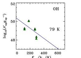
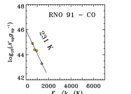
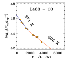
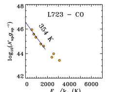

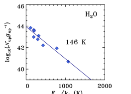
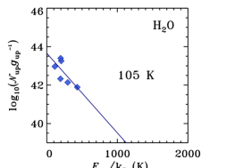
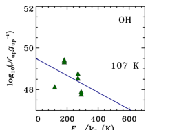
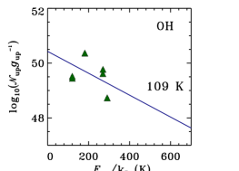
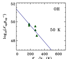
| ID | Source | Full spectra | WISH line scan | WILL line scan | |||
|---|---|---|---|---|---|---|---|
| (K) | (K) | (K) | |||||
| 3 | L1448 C(N) | 152(18) | 46.3(0.2) | 151(19) | 46.4(0.2) | 176(24) | 46.2(0.2) |
| 4 | L1448 C(S) | 84(11) | 46.3(0.3) | 89(14) | 46.3(0.3) | 83(16) | 46.1(0.4) |
| 6 | L1455 IRS1 | 124(30) | 45.6(0.3) | 97(24) | 45.6(0.3) | 132(18) | 45.4(0.2) |
| 14 | NGC1333 I4A | 105(18) | 46.4(0.3) | 97(14) | 46.0(0.2) | 97(21) | 45.7(0.4) |
| 16 | NGC1333 I4B | 183(15) | 46.5(0.1) | 145(16) | 46.7(0.2) | 153(13) | 46.5(0.2) |
| 22 | IRAS03301 | 176(22) | 45.4(0.2) | 162(18) | 45.4(0.2) | 179(25) | 45.4(0.2) |
| 25 | B1 a | 211(54) | 45.3(0.3) | 169(47) | 45.6(0.4) | 186(49) | 45.3(0.3) |
| 31 | L1489 | 191(22) | 45.1(0.2) | 172(22) | 45.2(0.2) | 193(29) | 45.1(0.2) |
| 42 | TMR1 | 193(31) | 45.4(0.2) | 211(41) | 45.4(0.2) | 239(66) | 45.4(0.3) |
| 44 | TMC1 | 148(24) | 44.9(0.2) | 143(28) | 44.9(0.3) | 174(46) | 44.8(0.3) |
| 48 | BHR71 | 125(23) | 45.8(0.3) | 138(33) | 45.9(0.4) | 146(38) | 45.6(0.4) |
| 52 | GSS30 IRS1 | 245(22) | 46.0(0.1) | 217(32) | 46.1(0.2) | 201(23) | 46.0(0.2) |
| 53 | VLA 1623 | 165(40) | 45.3(0.3) | 96(15) | 45.5(0.3) | 106(28) | 45.4(0.4) |
| 54 | WL12 | 202(25) | 45.0(0.2) | 149(20) | 45.2(0.2) | 187(22) | 45.0(0.2) |
| 56 | Elias29 | 288(33) | 46.0(0.1) | 236(35) | 46.0(0.2) | 231(33) | 45.9(0.2) |
| 66 | Ser SMM1 | 103(12) | 47.3(0.2) | 107(9) | 47.4(0.2) | 116(12) | 47.2(0.2) |
| 82 | RCrA IRS5A | 219(30) | 45.1(0.2) | 202(33) | 45.2(0.2) | 222(48) | 45.1(0.3) |
| 84 | RCrA IRS7A | 218(24) | 46.0(0.2) | 183(18) | 46.1(0.2) | 209(27) | 45.9(0.2) |
| 85 | RCrA IRS7B | 208(28) | 45.3(0.2) | 177(23) | 45.5(0.2) | 198(36) | 45.3(0.3) |
| 88 | B335 | 140(40) | 44.7(0.4) | 159(51) | 44.8(0.3) | 111(36) | 44.7(0.5) |
| 89 | L1157 | 114(20) | 46.3(0.3) | 101(15) | 46.2(0.2) | 99(23) | 46.1(0.4) |
| ID | Source | Full spectra | WISH line scan | WILL line scan | |||
|---|---|---|---|---|---|---|---|
| (K) | (K) | (K) | |||||
| 3 | L1448 C(N) | 123(17) | 52.2(0.2) | 113(91) | 52.3(0.7) | 33(6) | 54.4(0.6) |
| 4 | L1448 C(S) | 94(18) | 51.7(0.3) | 54(16) | 52.3(0.6) | 29(4) | 54.1(0.6) |
| 6 | L1455 IRS1 | 37(15) | 53.2(1.2) | 37(15) | 53.4(1.2) | 37(15) | 53.4(1.2) |
| 14 | NGC1333 I4A | 150(214) | 51.6(0.9) | 150(214) | 51.6(0.9) | 35(17) | 53.8(1.5) |
| 16 | NGC1333 I4B | 84(14) | 52.8(0.3) | 109(84) | 52.5(0.7) | 35(9) | 54.5(0.8) |
| 22 | IRAS03301 | 109(20) | 52.1(0.3) | 181(208) | 51.9(0.6) | 43(13) | 53.5(0.8) |
| 25 | B1 a | 103(20) | 51.8(0.3) | 163(196) | 51.7(0.7) | 44(21) | 53.3(1.2) |
| 31 | L1489 | 102(18) | 51.5(0.3) | 102(70) | 51.5(0.7) | 37(12) | 53.3(0.9) |
| 42 | TMR1 | 108(24) | 51.8(0.3) | 132(141) | 51.7(0.8) | 32(8) | 54.1(0.9) |
| 44 | TMC1 | 103(19) | 51.5(0.3) | 103(73) | 51.5(0.7) | 35(10) | 53.4(0.9) |
| 48 | BHR71 | 87(17) | 52.1(0.4) | 72(41) | 52.2(0.8) | 29(9) | 54.5(1.1) |
| 52 | GSS30 IRS1 | 99(18) | 52.2(0.3) | 110(84) | 52.2(0.7) | 34(8) | 54.2(0.7) |
| 53 | VLA 1623 | 71(16) | 51.9(0.4) | 126(117) | 51.6(0.7) | 48(30) | 52.8(1.4) |
| 54 | WL12 | 94(17) | 51.5(0.3) | 112(94) | 51.4(0.7) | 34(9) | 53.5(0.9) |
| 56 | Elias29 | 112(27) | 52.1(0.3) | 149(167) | 52.1(0.7) | 36(10) | 54.2(0.8) |
| 66 | Ser SMM1 | 83(13) | 53.6(0.3) | 109(79) | 53.4(0.7) | 42(17) | 54.9(1.1) |
| 82 | RCrA IRS5A | 113(17) | 51.9(0.3) | 86(70) | 52.0(1.0) | 30(5) | 54.4(0.6) |
| 84 | RCrA IRS7A | 114(17) | 52.9(0.3) | 90(80) | 52.9(1.0) | 31(11) | 55.1(1.2) |
| 85 | RCrA IRS7B | 119(17) | 52.0(0.3) | 104(100) | 52.0(0.9) | 33(8) | 54.1(0.8) |
| 88 | B335 | 101(63) | 51.1(0.6) | 101(63) | 51.1(0.6) | 60(42) | 51.7(1.3) |
| 89 | L1157 | 77(40) | 52.5(0.7) | 77(40) | 52.5(0.7) | 32(9) | 54.4(0.9) |
Appendix B Line cooling
The distribution of line luminosities for various species across the entire sample is illustrated in Figure B.8 (see also Table 5).
Luminosity ratios of selected species as a function of bolometric temperature are shown in Figure B.11.
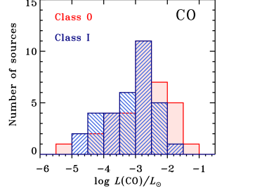
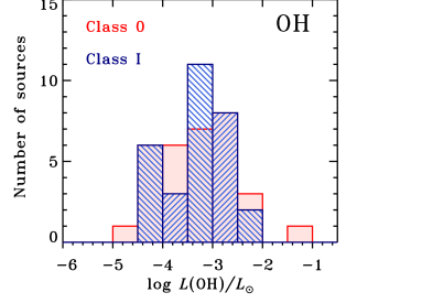
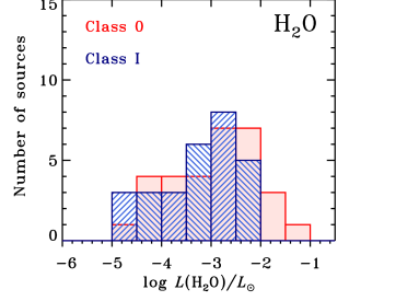
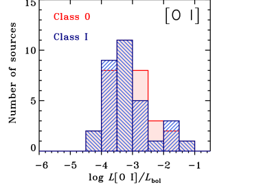
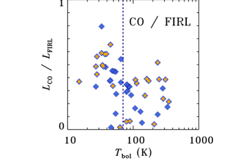
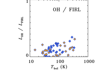
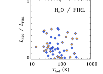
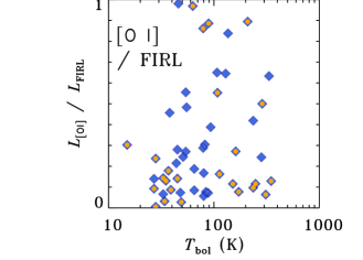
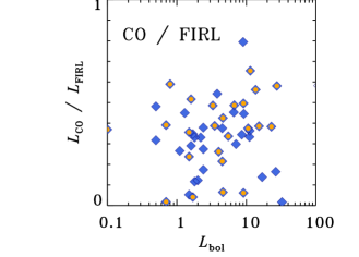
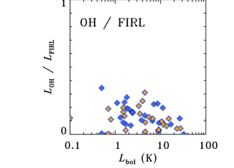
s
