Stabilisation of the Arrival Time of a Relativistic Electron Beam to the 50 fs Level
Abstract
We report the results of a low-latency beam phase feed-forward system built to stabilise the arrival time of a relativistic electron beam. The system was operated at the Compact Linear Collider (CLIC) Test Facility (CTF3) at CERN where the beam arrival time was stabilised to approximately 50 fs. The system latency was ns and the correction bandwidth MHz. The system meets the requirements for CLIC.
High-energy linear electron-positron colliders have been proposed as next-generation particle accelerators for exploring the subatomic world with increased precision. They provide sensitivity to new physics processes, beyond those described by the Standard Model (SM) of elementary particle interactions, at mass scales that can exceed the reach of the CERN Large Hadron Collider (LHC) CLIC and CLICdp collaborations (2016).
The Compact Linear Collider (CLIC) Aicheler et al. (2012) is the most technologically mature concept of a high-energy lepton collider for enabling direct searches for new physics in the multi-TeV energy regime. It uses a novel two beam acceleration concept to achieve a high accelerating gradient of 100 MV/m and centre-of-mass collision energies of up to 3 TeV. This energy reach, combined with high-luminosity of the electron-positron collisions, will also enable precise measurements of properties of the Higgs boson Abramowicz et al. (2016) and the top quark, and provide sensitivity to beyond-SM phenomena CLIC and CLICdp collaborations (2016).
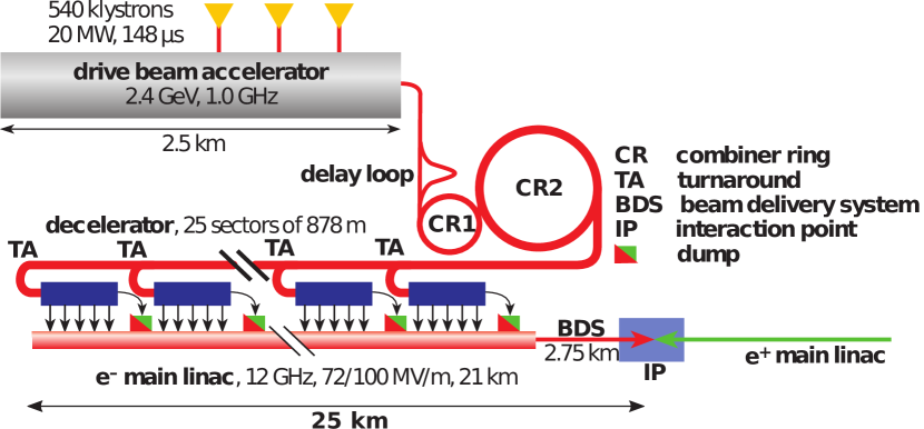
The CLIC two-beam acceleration concept is shown schematically in Fig. 1. The 12 GHz RF power used to accelerate the colliding electron and positron beams is extracted from high intensity ‘drive beams’. The drive beams are 2.4 GeV electron beams, with an initial bunch frequency of 0.5 GHz, a pulse length of , and a pulse repetition rate of 50 Hz. The intensity of the drive beams is increased by a factor 24 using a bunch recombination process Aicheler et al. (2012), thereby creating a series of 240 ns pulses bunched at 12 GHz. Each 240 ns sub-pulse is directed into a ‘decelerator sector’, in which the drive beam pulse is decelerated, producing 12 GHz RF power which is transferred to the accelerating structures of the main beams. Two drive beams with 25 decelerator sectors each are required for a 3 TeV collider.
One of the major challenges is the synchronisation of the arrival of the drive and main beams at the power-extraction and transfer structures to better than 50 fs rms. This requirement limits the luminosity loss, resulting from subsequent energy errors of the main beams, to less than 1% of the design value Schulte and Tomas (2009). Free-electron lasers (FELs) also demand a high degree of beam arrival-time stability w.r.t. an externally-applied laser beam for the purpose of seeding of lasing by the electron beam Savelyev et al. (2017).
We express the temporal stability of the drive beam in terms of phase stability at the 12 GHz acceleration frequency. An arrival time jitter of 50 fs rms is equivalent to a phase jitter of at 12 GHz. In the CLIC design the incoming drive-beam phase jitter cannot be guaranteed to be better than Aicheler et al. (2012). A mechanism to improve the phase stability by an order of magnitude is therefore required. The correction must be applied to the full drive beam pulse length and have a bandwidth exceeding 17.5 MHz. This bandwidth is derived from simulations of the system performance whilst assuming a pessimistic frequency spectrum of the incoming phase errors Gerbershagen et al. (2015).
This is implemented via a ‘phase feed-forward’ (PFF) system which measures the incoming beam phase and provides a correction to the same beam pulse after it has traversed the turnaround loop (TA in Fig. 1). One PFF system will be installed in each deceleration sector. The correction is provided by electromagnetic kickers in a 4-bend chicane: bunches arriving early (late) in time have their path through the chicane lengthened (shortened) respectively. A particular challenge is that the PFF latency must be shorter than the beam flight time of approximately. 250 ns around the turnaround loop.
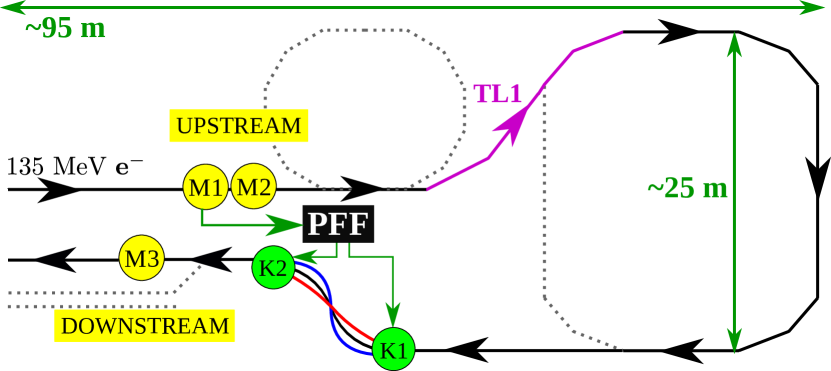
We describe a prototype PFF system (Fig. 2) that implements this novel concept at the CLIC Test Facility (CTF3) at CERN. CTF3 provides a 135 MeV electron beam bunched at 3 GHz frequency with a beam-pulse length of 1.2 and a pulse repetition rate of 0.8 Hz Aicheler et al. (2012).
The incoming beam phase is measured in two upstream phase monitors (). While the beam transits the ‘turnaround loop’ a phase-correction signal is evaluated and used to drive fast, high power amplifiers; these drive two electromagnetic kickers () which are used to alter the beam transit time in a four-bend chicane. A downstream phase monitor () is used to measure the effect of the correction.
The beam time of flight between and is around 380 ns. The total cable delay for the PFF correction signals is shorter, around 250 ns. The correction in the chicane can therefore be applied to the entirety of the beam pulse measured at the PFF input (, the measured phase at ), provided that the hardware latency is less than 130 ns. Significant hardware challenges include the resolution and bandwidth of the phase monitors, and the power, latency and bandwidth of the kicker amplifiers. A low latency digitiser/feedforward controller is also required.
The requirements of the CLIC system and their corresponding CTF3 values are listed in Table 1. The main differences result from the different drive-beam energies. Higher power amplifiers (500 kW rather than 20 kW) are required for CLIC, which may be achieved by combining the output of multiple modules similar to those built for CTF3. CLIC also requires a distributed timing system to synchronise the phase of the drive and main beams along the 50 km facility, which is not addressed here.
| CLIC | CTF3 | ||
|---|---|---|---|
| Drive beam energy | 2400 | 135 | MeV |
| No. PFF systems | 50 | 1 | |
| Kickers per PFF chicane | 16 | 2 | |
| Power of kicker amplifiers | 500 | kW | |
| Angular deflection per kicker | |||
| Correction range | ∘ | ||
| Correction bandwidth | MHz | ||
| Phase monitor resolution | ∘ | ||
| Initial phase jitter | ∘ | ||
| Corrected phase jitter | ∘ |
The phase monitors Marcellini et al. (2014) are cylindrical cavities with an aperture of 23 mm and a length of 19 cm. Small ridges (’notch filters’) in the cavity create an effective volume with a resonant frequency of 12 GHz. The field induced by the beam traversing the cavity contains a beam-position-independent monopole mode and an unwanted position-dependent dipole mode. The effect of the latter is removed by summing the outputs from an opposing pair of feedthroughs, on the top and bottom of the cavity, via a RF ‘hybrid’. To extract the beam phase the output from each hybrid is mixed with a 12 GHz reference signal derived from a 3 GHz source which is phase-locked to the CTF3 RF system and serves all three phase monitors. By comparing the signals from and we have measured a phase resolution of , i.e. about 30 fs Roberts (2016).
The phase signals are digitised in the feedforward controller board Roberts (2016), which is used to calculate and output the amplifier drive signals, and to control the correction timing. It consists of nine 14-bit analogue to digital converters clocked at 357 MHz, a field programmable gate array, and four digital to analogue converters.
The kicker amplifiers Roberts (2016) consist of one central control module and two drive and terminator modules (one per kicker). The control module distributes power and input signals to the drive modules. The 20 kW drive modules consist of low-voltage Si FETs driving high-voltage SiC FETs; an input voltage range of V corresponds to an output range of V. The response is linear to within 3% for input voltages between V, and the output bandwidth is 47 MHz for small signal variations of up to 20% of the maximum. For larger signal variations the bandwidth is slew-rate limited.
The two electromagnetic stripline kickers Ghigo et al. (2011) are 1 m in length and have an internal aperture of 40 mm between two strips placed along their horizontal walls. They are designed to give a response within a few ns of the input signal. Opposite polarity voltages of up to 700 V applied to the strips at the downstream end horizontally deflect the 135 MeV beam by up to 560 rad.
The measured total latency of the phase monitor signal processing, the feedforward calculation, and amplifier response was approximately 100 ns. Therefore the output from the controller was delayed by an additional 30 ns to synchronise the correction at the kicker with the beam arrival Roberts (2016).
The PFF operation placed severe constraints on the setting of the magnetic lattice in both the beamline between the upstream phase monitors and the correction chicane, and in the chicane itself. The beam transfer matrix coefficient between the two kickers characterises the change in path length through the chicane relative to the deflection applied at the first kicker. With an value of m/rad Roberts (2016) the expected maximum path length change for operation of the PFF system, corresponding to the maximum deflection of rad from each kicker, is about , equivalent to in phase. The chicane magnets were also set so that PFF operation does not change the beam trajectory at the exit of the chicane Roberts (2016).
A further challenge to PFF operation was obtaining a high correlation between the upstream and uncorrected downstream phases measured at and respectively. The maximum measurable correlation depends on both the phase monitor resolution and any additional phase jitter introduced in the beamlines between and . The monitor resolution of limits the maximum upstream-downstream phase correlation to in typical conditions, and places a theoretical limit of on the measurable corrected downstream phase jitter. The dominant beam source of uncorrelated downstream phase jitter arises from energy jitter that is transformed into phase jitter in the beamlines between and .
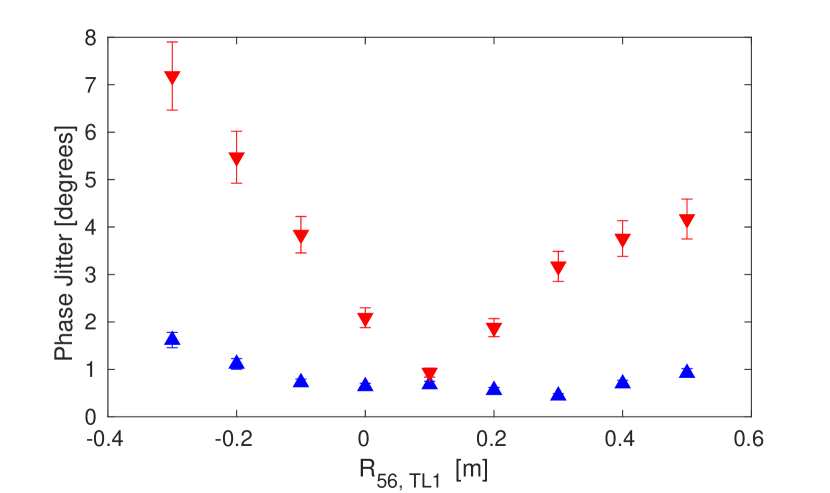
To first order the phase dependence on energy can be described via the beam transfer matrix coefficient : , where is the particle’s relative energy error, and are the phases measured at and respectively, and the constant m converts the units of from metres to degrees at 12 GHz ( per 0.025 m).
The optimal condition is = 0. This was achieved by tuning the value in the ‘TL1’ transfer line (Fig. 2) so as to compensate for non-zero in the other beamline sections. With cm the downstream phase jitter is reduced to the same level as the upstream jitter (Fig. 3). However, a large coefficient (second-order phase dependence on energy) remained uncorrected. As a result, drifts in beam energy lead to a degradation in upstream-downstream phase correlation even after optimising the term. Drifts in the CTF3 RF system, and the resulting changes in beam energy, therefore made it difficult to maintain maximal upstream-downstream phase correlation for timescales longer than 10 minutes. Optics for a future CLIC PFF system must zero both and the higher order energy dependences.
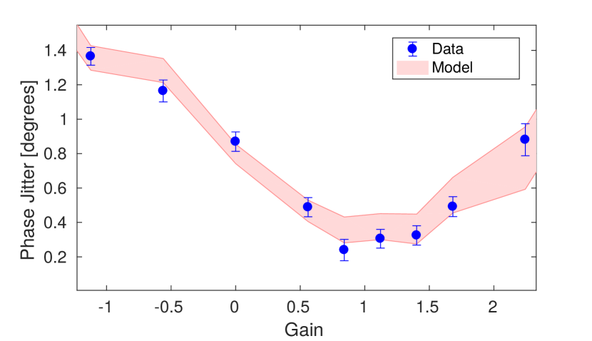
The PFF system acts to remove the phase, multiplied by a ‘gain’ factor, from the phase at . If the phases at and are fully correlated, and the jitters are identical, the optimal system gain is unity. In practice the gain is chosen to achieve optimal performance for real beam conditions. A representative gain scan is shown in Fig. 4. The optimal gain is typically in the range 0.9–1.3. Also shown in Fig. 4 is a prediction of the corrected phase jitter at , using a simple model including the initial beam phase jitters at and , the upstream-downstream phase correlation, and the gain Roberts (2016). The model reproduces the data.
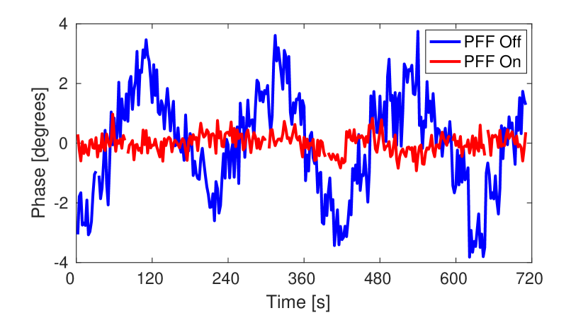
The PFF system simultaneously corrects pulse-to-pulse phase jitter and phase variations within the 1.2 beam pulse at CTF3. Fig. 5 shows the effect of the PFF system on the intra-pulse phase variations. The PFF system was operated in interleaved mode, with the correction applied to alternating pulses only. This allows the initial (‘PFF Off’) and corrected (‘PFF On’) downstream phase at to be measured at the same time. The (PFF input) phase is also shown for comparison.
It is an operational feature at CTF3 that there is a roughly parabolic phase sag of along the pulse, resulting from the upstream RF pulse compression scheme Aicheler et al. (2012). Hence approximately a 440 ns portion of the pulse is within the dynamic range of the PFF system, and can be corrected to zero nominal phase. This time duration for the full correction exceeds the CLIC drive-beam pulse length of 240ns and in any case the CLIC design avoids such a large phase sag Aicheler et al. (2012). Vertical dashed lines in Fig. 5 mark the 440 ns portion of the pulse where full correction is possible.
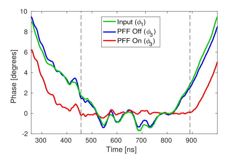
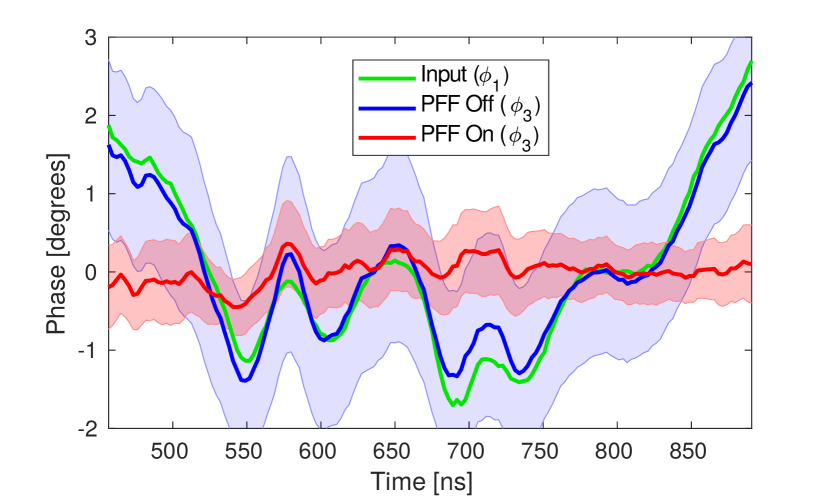
Within the range the PFF system flattens the phase, and almost all variations are removed. The average intra-pulse phase variation (rms) over the dataset is reduced from (PFF off), to (PFF on).
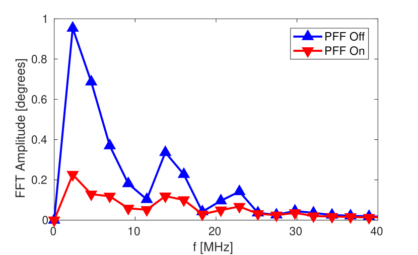
In order to meet CLIC requirements (Table 1) the PFF correction bandwidth should be at least 17.5 MHz. A Fourier-Transform (FFT) method was used to characterise the PFF on/off datasets. The FFT amplitude is shown vs. frequency in Fig. 6. It can be seen that phase errors are corrected by up to a factor of 5 for frequencies up to 23 MHz, above which they are smaller than the monitor resolution and not measurable. This is consistent with an expected system bandwidth of around 30 MHz, and exceeds the CLIC requirement.
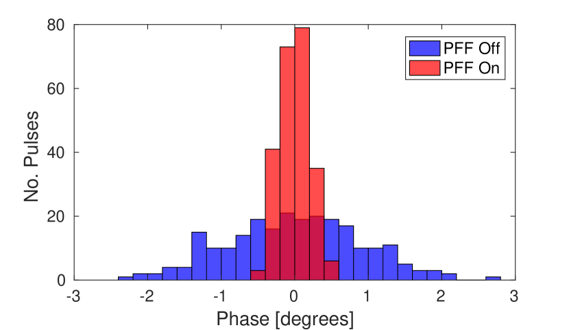
The effect of the PFF system on the pulse-to-pulse jitter, i.e. the jitter on the mean phase of each beam pulse, is shown in Fig 7 for a dataset of around ten minutes duration. The pulse-to-pulse phase jitter is reduced from to , meeting CLIC-level phase stability. The system acts to remove all correlations between the upstream and downstream phase, reducing an initial correlation of to for this dataset. Given the incoming upstream phase jitter and measured upstream-downstream correlation, the performance is consistent with the theoretically predicted correction of .
The system was further tested by varying the incoming mean beam phase systematically by around (Fig. 8). Variations of this magnitude are comparable to the expected conditions in the CLIC design (Table 1). This is illustrated in Fig. 8. The system removed the induced phase variations and achieved more than a factor-5 reduction in the downstream phase jitter, correcting from to .
In summary, we have built, deployed and tested a prototype drive-beam phase feedforward system for CLIC. The system incorporates purpose-built high-resolution phase monitors, an advanced signal-processor and feedforward controller, low-latency, high-power, high-bandwidth amplifiers, and electromagnetic stripline kickers. The phase-monitor resolution was measured to be 30 fs. The overall system latency, including the hardware and signal transit times, was measured to be approximately 350 ns, which is less than the beam time of flight between the input phase monitor and the correction chicane. The system was used to stabilise the pulse-to-pulse phase jitter to 50 fs, and to simultaneously correct intra-pulse phase variations at frequencies up to 23 MHz.
Our demonstration of a beam-based arrival-time stabilisation system with a performance at the 50 fs level has potential application at other beamlines where a high degree of beam arrival stability is required. For example, ‘pump-probe’ experiments at FELs require laser/electron synchronisation ideally to the few femtosecond level, see e.g. Savelyev et al. (2017). The current state-of-the-art in synchronisation at FELs is approximately 30 fs, using all-optical techniques Schulz et al. (2015). Our results are limited by the beam arrival-time monitor resolution of approximately 30 fs. With higher precision monitors (e.g. Löhl et al. (2010)) 10 fs stabilisation could be achieved with our technique. A key feature of our system is that it incorporates a beam turnaround, which provides sufficient beam delay to allow a feed-forward correction to be derived and applied with zero effective latency. FEL designs based on energy-recovery linacs (see e.g. Sekutowicz et al. (2005); Kim et al. (2008); Jackson et al. (2016)) intrinsically incorporate a beam turnaround section that would enable the deployment of a high-performance system based on our technique.
Acknowledgements.
We acknowledge Alessandro Zolla and Giancarlo Sensolini (INFN Frascati) for the mechanical design of the phase monitors and kickers, and Alexandra Andersson, Luca Timeo and Stephane Rey (CERN) for their support on the phase monitor electronics. We thank the operations team of CTF3 for their outstanding support. This work was supported by the the UK Science and Technology Facilities Council, and by the European Commission under the FP7 Research Infrastructures project Eu-CARD, grant agreement no. 227579.References
- CLIC and CLICdp collaborations (2016) CLIC and CLICdp collaborations, “Updated baseline for a staged compact linear collider,” CERN-2016-004 (2016).
- Aicheler et al. (2012) M. Aicheler et al., “CLIC conceptual design report,” CERN-2012-007 (2012).
- Abramowicz et al. (2016) H. Abramowicz et al., Eur. Phys. J. C (Submitted), CLICdp-Pub-2016-001 (2016).
- Schulte and Tomas (2009) D. Schulte and R. Tomas, in Proceedings of PAC09 (Vancouver, Canada, 2009) pp. 3811–3813.
- Savelyev et al. (2017) E. Savelyev et al., New. J. Phys 19, 043009 (2017).
- Gerbershagen et al. (2015) A. Gerbershagen et al., Phys. Rev. STAB 18, 041003 (2015).
- Marcellini et al. (2014) F. Marcellini et al., EuCARD-REP-2013-023 (2014).
- Roberts (2016) J. Roberts, DPhil thesis, University of Oxford (2016).
- Ghigo et al. (2011) A. Ghigo et al., in Proceedings of IPAC2011 (San Sebastian, Spain, 2011) pp. 1000–1002.
- Schulz et al. (2015) S. Schulz et al., Nat. Commun. 6, 5938 (2015).
- Löhl et al. (2010) F. Löhl et al., Phys. Rev. Let. 104, 144801 (2010).
- Sekutowicz et al. (2005) J. Sekutowicz et al., Phys. Rev. STAB 8, 010701 (2005).
- Kim et al. (2008) K. Kim et al., Phys. Rev. Let. 100, 244802 (2008).
- Jackson et al. (2016) F. Jackson et al., Phys. Rev. STAB 19, 120701 (2016).