Wrinkles, folds and plasticity in granular rafts
Abstract
We investigate the mechanical response of a compressed monolayer of large and dense particles at a liquid-fluid interface: a granular raft. Upon compression, rafts first wrinkle; then, as the confinement increases, the deformation localizes in a unique fold. This characteristic buckling pattern is usually associated to floating elastic sheets and as a result, particle laden interfaces are often modeled as such. Here, we push this analogy to its limits by comparing the first quantitative measurements of the raft morphology to a theoretical continuous elastic model of the interface. We show that although powerful to describe the wrinkle wavelength, the wrinkle-to-fold transition and the fold shape, this elastic description does not capture the finer details of the experiment. We describe an unpredicted secondary wavelength, a compression discrepancy with the model and a hysteretic behavior during compression cycles, all of which are a signature of the intrinsic discrete and frictional nature of granular rafts. It suggests also that these composite materials exhibit both plastic transition and jamming dynamics.
Simple compression tests are commonly conducted on a material to probe its mechanical properties. When performed on an elastic film resting on a foundation, wrinkling patterns and then a localization into a single fold is observed Pocivavsek et al. (2008); Leahy et al. (2010); Brau et al. (2011); Kim et al. (2011); Piñeirua et al. (2013); Paulsen et al. (2017). This wrinkle-to-fold transition has explained in recent years the formation of patterns in various systems, such as the wrinkling of the skin, the multilayer folds observed in geological layers or the cortical folding in the fetal brain Cerda and Mahadevan (2003); Pollard and Fletcher (2005); Tallinen et al. (2016).
However, many practical situations in biology and industry involve complex membranes formed of discrete objects. Such composite interfaces can be as diverse as pulmonary surfactant monolayers, which are compressed and expanded upon exhalation thus preventing lung collapse Boatwright et al. (2010), biofilms on water, that form wrinkles when confined Trejo et al. (2013), or ultra-thin layers of nanoparticles placed at an air-water interface Schultz et al. (2006); Mueggenburg et al. (2007). In addition, many fundamental studies have focused on interfaces coated with proteins, soaps or particles since they stabilize or rigidify emulsion Binks (2002). In this context, densely packed monolayers present some characteristics of elastic sheets: they can sustain shear and buckle out of plane to form wrinkles Vella et al. (2004); Protière et al. (2017). Different elastic moduli can also be measured by using a Langmuir-Blodgett trough, by manipulating particle-coated droplets or by creating surface waves Cicuta et al. (2003); Vella et al. (2004); Monteux et al. (2007); Planchette et al. (2012); Varshney et al. (2012); Lagubeau et al. (2014). The possibility of particle rearrangement and jamming Liu and Nagel (1998); O’Hern et al. (2005); Liu and Nagel (2010); Bi et al. (2011) together with the presence of chain forces between grains Radjai et al. (1996); Cates et al. (1998), coupled with a liquid interface suggest also that these discrete frictional sheets represent an original material more complicated than a pure elastic membrane Cicuta et al. (2003); Subramaniam et al. (2005); Cicuta and Vella (2009); Varshney et al. (2012); Lagubeau et al. (2014). For instance, elastic instabilities coupled with the discrete character of the interface are responsible for the dramatic sinking of granular rafts Abkarian et al. (2013); Vella (2015); Protière et al. (2017), implying that large deformations of such rafts lead to new behaviors. Thus, the intrinsic discrete nature of such objects is a key parameter and it is crucial to question the validity and test the limitations of the analogy of such composite materials with elastic sheets.
In this Letter, we first present an experiment where a wrinkle-to-fold transition is observed in particle monolayers at a liquid-fluid interface suggesting that such systems behave like an elastic sheet. However, by investigating further the limits of a continuum elastic model, we reveal that these composite materials also have very specific mechanical properties: for large deformations, what seems to be at first a pure elastic response is in fact an irreversible plastic transition that can only be rejuvenated through an annealing stirring process.
Rafts are made by sprinkling carefully dense particles above a planar liquid/fluid interface. The particles straddle either an oil-water or air-water interface where they are trapped and aggregate, forming a monolayer of particles, the granular raft. Most of the experiments were conducted with polydisperse beads in zirconium oxide “ZrO” () from Glen Mills Inc. or coated glass “SiO” () from Sigmund Lindner. The water is deionized, the oil is light mineral oil (Sigma Aldricht) of density and the interfacial tension is . Particle diameter and oil-water contact angle vary in the range: and (see Supplemental Material Note (1)). A typical freely floating granular raft consists of a flat central region below the water surface and curved menisci at its edges. Its stability and shape have been studied in detail Protière et al. (2017) and are determined by a balance between gravity, buoyancy effects and surface tension. In particular, the depth of the flat region is determined by buoyancy and weight of the particles at equilibrium.
To compress the raft, a glass plate is mounted to a step motor of micrometer precision (Thorlabs) that moves uniaxially enabling its incremental compression along the -axis (fig. 1(a)). Compression is controlled in steps of every to let the raft relax to its equilibrium shape at each step.
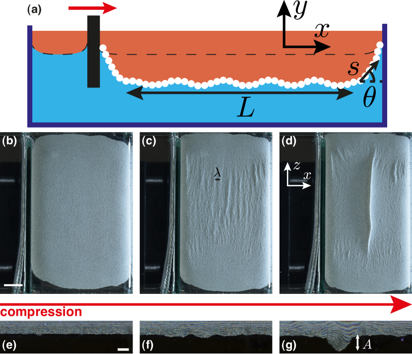
The raft is imaged from the side and the bottom with two cameras (Nikon D800E), and fringes are projected on its surface to reconstruct it using Fourier transform profilometry Takeda and Mutoh (1983); Cobelli et al. (2009); Note (1). At first, when the raft is compressed, the particles have enough space to rearrange and the raft elongates along the axis in order to accommodate the compression. Then, when the particles are confined along the interface, grain-to-grain interactions make rearrangements difficult and the raft starts to buckle out of plane: we observe pseudo-sinusoidal deformations of wavelength along the raft which are perpendicular to the direction of compression (fig. 1 (c), (f)) until finally at a critical compression these small deformations localize into one large fold (fig. 1 (d), (g)) (see full movie Note (1)).
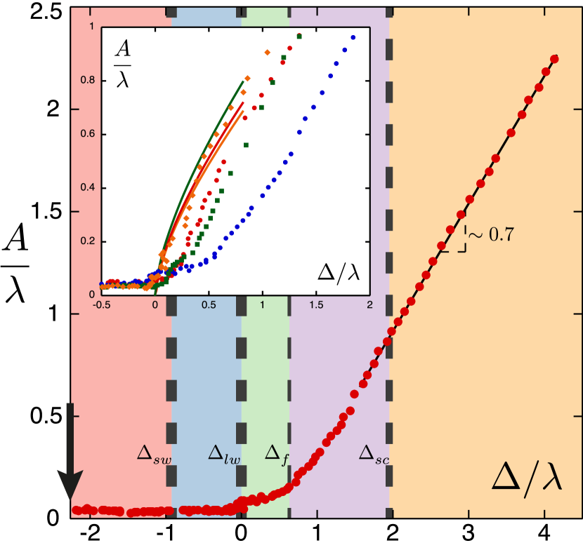
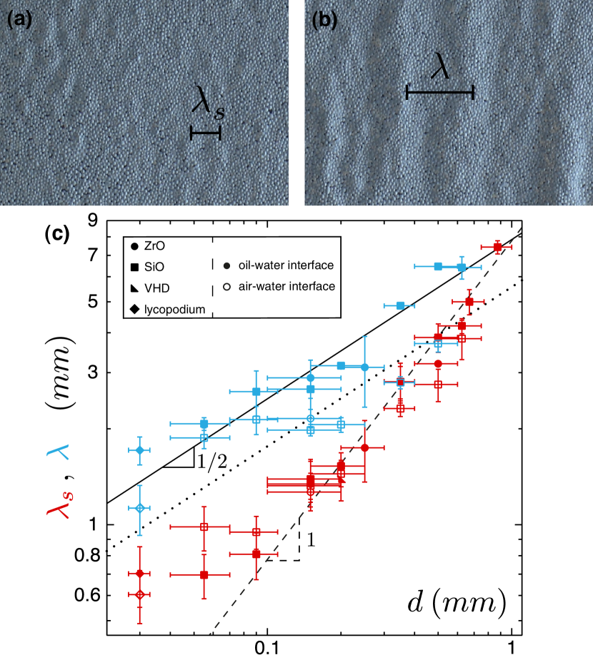
To quantify this fold formation we measure the compression imposed to the raft. When the raft reaches the solid boundaries, particles climb up the menisci whose shape is defined by the wall’s wetting properties. It thus forms a complex structure depending on both the wall and raft characteristics which can rotate and bend during the compression, absorbing and releasing large stresses and strains (fig. 2 and details in Note (1)). To simplify the problem, we only consider the large flat region (of initial aspect ratio ) that is always present in the center (fig. 1 (a)). By analogy with the compression of an elastic sheet, we define the confinement as , corresponding to the length of that flat region and its length when the wrinkles in Fig 3 (c) are first observed. We further measure the amplitude of the wrinkles as we increase the confinement incrementally (fig. 3 for a typical experiment with ”ZrO” particles at an oil-water interface, ). Five different regions are identified: in region I (the raft edges touch both plates, black arrow fig. 3) the particles rearrange as explained above. At a critical starts region II where a careful examination reveals small undulations in some regions of the raft surface (of wavelength , fig. 4 (a)). These small wrinkles, have a small lateral extension (along ) and their amplitude is smaller than the resolution of our measurment (roughly ). They gradually appear on the whole raft as we increase compression until . Above this threshold (region III), the wrinkles, of wavelength , grow in length and amplitude (fig. 1 (c),(f)). Then an abrupt transition occurs around : one of the wrinkles starts to grow much faster than the others thus creating a large fold at the center of the raft (fig. 1 (d),(g)), region IV. This fold grows in amplitude and along the -direction upon further compression while the other wrinkles disappear progressively (see Note (1)). Its amplitude grows then linearly with compression indicating that all the deformation is now localized in the fold (fig. 3). At both sides of the fold come into contact , encapsulating a small oil volume, region V. Finally the last point of the curve corresponds to the critical compression at which most of the raft’s weight is pulled into the fold leading to the raft destabilization.
By varying liquids and particle properties, we observe that only varies linearly with the particle diameter (fig. 4 (c)). This is similar to what is observed for a particle monolayer stuck to an elastic solid Tordesillas et al. (2014), revealing the discrete nature of the granular raft Taccoen et al. (2016). By contrast, when measuring the large wrinkles wavelength, varies with and depends on the liquids used, but neither on the particle density nor on the contact angle. These types of wrinkles have elastic origin and have already been observed on compressed particle rafts Kassuga and Rothstein (2015); Vella et al. (2004). The elastic description of the interface Vella et al. (2004) predicts indeed (with the capillary length) while our data are well fitted by: (fig. 4 (c)), confirming the dependence on and also showing the variation with .
Keeping the elastic analogy for the particle raft, we describe it as a continuous heavy elastic sheet of length , width , thickness , density and bending rigidity (per unit width) floating between two liquids (of density and ) Jambon-Puillet et al. (2016). This approach generalizes the simple first model that was derived for axisymmetric membranes where only isotropic tension was considered, that could not capture the formation of wrinkles and thus the elastic nature of the rafts Protière et al. (2017). More precisely, it consists of adding the grains’ weight to the model developed for a 2D Euler-Bernoulli beam floating between two liquids Pocivavsek et al. (2008); Rivetti and Neukirch (2014) and assume thus the invariance of the raft in the width direction. The elastic feature of the granular raft has different origins that act as additional contributions: the first one comes from the interface menisci between the grains whose deformation generates elasticity (with an associated Young modulus ) Vella et al. (2004); in addition, the chain forces that are present in granular systems are also known to lead to an elastoplastic behavior of the raft Cates et al. (1998); Bouchaud et al. (2001). The balance of dimensionless internal forces (, ) and bending moment along with the kinematic and bending constitutive relation yield:
| (1) |
Here, the intrinsic coordinates (, ) are the arc-length and the local angle between the raft and the horizontal axis respectively (see fig. 1 (a)). The sheet centerline is parametrised by . Here the surface tension is embedded in the internal forces acting in the raft, that account also for the contact force between the grains. The system has been made dimensionless by dividing all lengths by , forces by and moments by . Since we neglect the deformation of the raft menisci in the experiments we also remove them from the model in order to solve the equation only for the flat portion of the sheet located below the water surface. The dimensionless boundary conditions read:
| (2) |
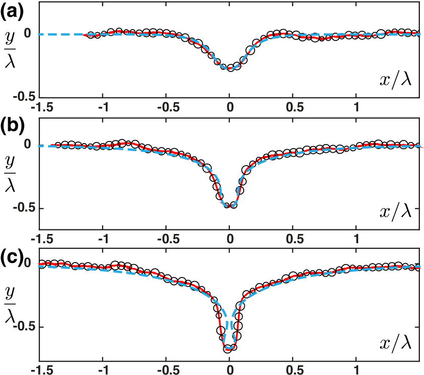
where is the dimensionless parameter introduced in Jambon-Puillet et al. (2016) that compares the weight of the sheet to the restoring force provided by the fluids displaced over the length . The boundary condition at the edges of the sheet simply means that the sheet is clamped at its freely floating location, i.e. where its weight is balanced by the displaced fluid. We solve numerically the system of equations (1) with the boundary conditions (2) using the MATLAB routine bvp5c with a continuation algorithm. The raft bending rigidity is determined using the experimental through . The effective density takes into account the voids in the sheet and the fact that the particles are immersed. For a monolayer of spherical monodisperse particles half immersed in oil and water where is the 2d packing fraction ( for jammed polydisperse systems, the factor accounts for the 3d volume corresponding to this 2d packing fraction). To compare the data with the theoretical model, we plot the dimensionless amplitude as a function of compression at the wrinkle-to-fold transition for different types of particles (inset fig. 3). At first glance, the variation of the fold amplitude during compression is well captured by the continuous description, with no adjustable parameter. However, while this elastic continuous sheet model predicts that the wrinkle-to-fold transition always occurs around Note (1), we find experimentally higher values. In addition, two identical rafts may buckle at a different . Such behavior is the signature of the granular nature of this composite material, where individual particles rearrange during the compression process, leading to inhomogeneous stress and strain repartition, inducing jamming, frustration and residual chain forces in the system Liu and Nagel (1998); Cates et al. (1998); Bouchaud et al. (2001). This can be clearly seen on fig. 1(d) where the fold already is formed while some wrinkles are still present. Interestingly, when we compare the experimental and theoretical (using the continuous elastic model) fold profiles at the same amplitude (and thus not formally obtained for the same global compression ), we observe a good quantitative agreement, as shown on fig. 5 (a)-(c).
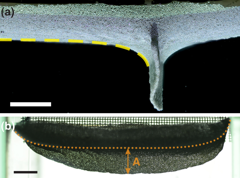
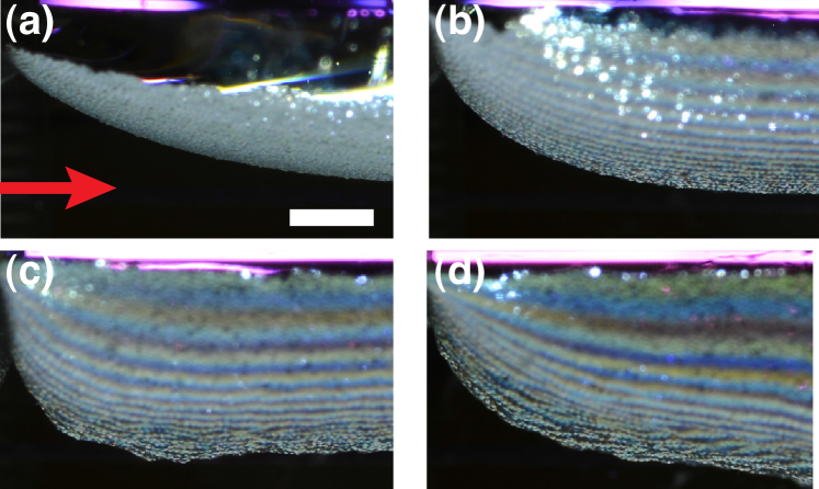
In particular, the agreement between the two profiles are good in region IV (fig. 5 (a) and (b)), validating that the compression difference is due to rearrangements that do not affect the fold formation. As we reach self-contact (region V), the fold in the model forms a loop not observed experimentally (see fig. 5(c)). Because the model represents the sheet centerline and does not account its thickness , self-contact occurs when the neck width is equal to and stops the loop formation. Since is roughly the size of the final loop and the polydispersity of our particles is important, we observe a vertical fold of width after self-contact. The model cannot describe the full raft profile beyond the critical compression (end of black curves in inset fig. 3 (a)) since the numerical fold then starts to interpenetrate. However, in region V, the fold profiles can still be described outside of the self-contact zone using the elastic sheet model only by changing the boundary conditions appropriately, exhibiting a self-similar evolution with (dashed line of fig. 6(a) Note (1)). Fig. 6(b) presents the lateral structure of the fold, showing that the fold is also localized in this direction as it could be observed on fig. 1 (d). This shape is due to stress inhomogeneities, the edge of the fold being here less confined. At the center of the fold, where we extract the profiles and measure , the raft’s depth only varies slowly.
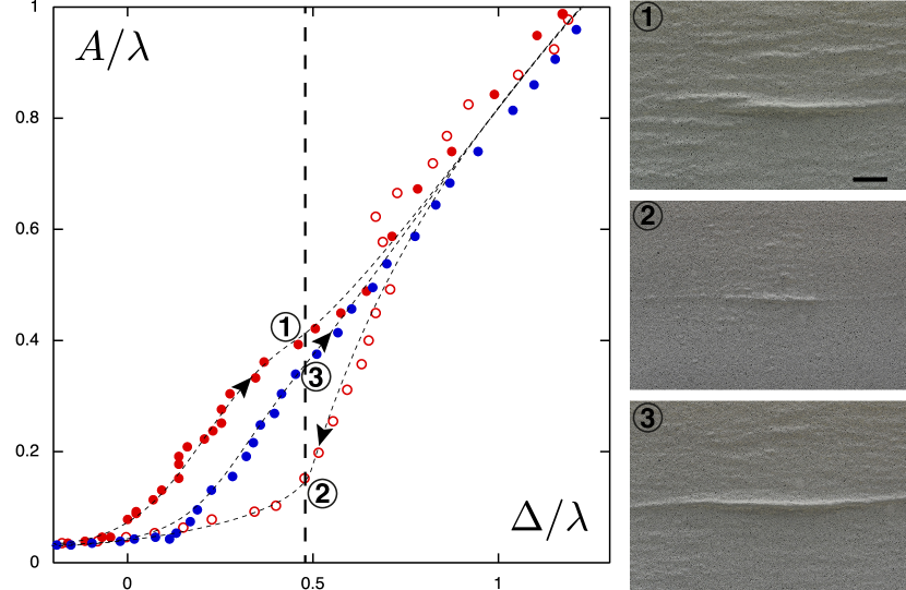
To investigate the influence of particle rearrangements, we study the reversibility of the folding process by performing cycles of compression and unloading of the raft, being careful not to reach the critical compression at which the raft destabilizes. When we plot the evolution of the amplitude during each cycle we observe a hysteresis behavior (fig. 7). The first compression is similar to the one described earlier (fig. 7 (1)). Then, as the confinement is decreased progressively the raft unfolds and recovers a flat surface without going through the wrinkled state. In addition, a small ”scar” remains present at the initial fold position even when the compression is completely released, as it can be seen on fig. 7 (2): there the particles seem to be aligned along the scar. During the second compression cycle the raft localizes directly into a single fold exactly at the scar location (fig. 7 (3)), without going through a wrinkle-to-fold transition. Furthermore, if compression/relaxation cycles are repeated further on, they always form the same fold and follow after few cycles the same curves (close to the curves 2 and 3 in the diagram of fig. 7). This behavior suggests that the granular raft exhibits a plastic irreversible transition when the fold reaches the self-contact that acts as the plastic threshold. The fold can be considered here as an analogue to a ridge in crumpled papers Deboeuf et al. (2013). It is tempting therefore to associate this plastic transition to the elastoplastic behavior of grains under compaction that exhibit a network of intense force chains Cates et al. (1998); Bouchaud et al. (2001). However, if we stir thoroughly the raft to force a new random particle arrangement, we recover the behavior observed when the raft is first compressed: the raft elastic property is recovered through this annealing process similarly to what is observed in amorphous materials Raty et al. (2015), spin glasses Alberici-Kious et al. (1998), vibrated grains Josserand et al. (2000) or shape memory polymers Pilate et al. (2016). In our system, the annealing process is probably related to the breakdown of the chain forces that are related to the jamming of the granular raft O’Hern et al. (2005); Liu and Nagel (2010); Bi et al. (2011).
In conclusion, we show in this Letter that under large compression a granular raft deviates from the elastic sheet model since it undergoes an irreversible plastic transition. This new transition is different from the reversible wrinkle-to-fold one observed also for elastic sheets. Moreover, the particle rearrangements act as an effective temperature in the system that can anneal the plastic transition. This composite material made of interacting grains at interface share properties both of elastoplastic sheets, as well as amorphous and discrete materials.
Acknowledgements.
The authors thank Manouk Abkarian for many valuable discussions at the early stages of this work and Sébastien Neukirch for fruitful conversations concerning the model.References
- Pocivavsek et al. (2008) L. Pocivavsek, R. Dellsy, A. Kern, S. Johnson, B. Lin, K. Y. C. Lee, and E. Cerda, Science 320, 912 (2008).
- Leahy et al. (2010) B. D. Leahy, L. Pocivavsek, M. Meron, K. L. Lam, D. Salas, P. J. Viccaro, K. Y. C. Lee, and B. Lin, Phys. Rev. Lett. 105, 058301 (2010).
- Brau et al. (2011) F. Brau, H. Vandeparre, A. Sabbah, C. Poulard, A. Bouadoud, and P. Damman, Nat. Phys. 7, 56 (2011).
- Kim et al. (2011) P. Kim, M. Abkarian, and H. A. Stone, Nat. Mater. , 952 (2011).
- Piñeirua et al. (2013) M. Piñeirua, N. Tanaka, B. Roman, and J. Bico, Soft Matter 9, 10985 (2013).
- Paulsen et al. (2017) J. D. Paulsen, V. Démery, K. B. b. u. Toga, Z. Qiu, T. P. Russell, B. Davidovitch, and N. Menon, Phys. Rev. Lett. 118, 048004 (2017).
- Cerda and Mahadevan (2003) E. Cerda and L. Mahadevan, Phys. Rev. Lett. 90, 074302 (2003).
- Pollard and Fletcher (2005) D. D. Pollard and R. C. Fletcher, Fundamentals of Structural Geology (Cambridge University Press, 2005).
- Tallinen et al. (2016) T. Tallinen, J. Y. Chung, F. Rousseau, N. Girard, J. Lefevre, and L. Mahadevan, Nat Phys 12, 588 (2016).
- Boatwright et al. (2010) T. Boatwright, A. J. Levine, and M. Dennin, Langmuir 26, 12755 (2010).
- Trejo et al. (2013) M. Trejo, C. Douarche, V. Bailleux, C. Poulard, S. Mariot, C. Regeard, and E. Raspaud, Proc. Natl. Acad. Sci. U.S.A 110, 2011 (2013).
- Schultz et al. (2006) D. G. Schultz, X.-M. Lin, D. Li, J. Gebhardt, M. Meron, J. Viccaro, and B. Lin, J. Phys. Chem. B 110, 24522 (2006).
- Mueggenburg et al. (2007) K. E. Mueggenburg, X.-M. Lin, R. H. Goldsmith, and H. M. Jaeger, Nat. Mater. 6, 656 (2007).
- Binks (2002) B. P. Binks, Curr. Opin. Colloid Interface Sci. 7, 21 (2002).
- Vella et al. (2004) D. Vella, P. Aussillous, and L. Mahadevan, Europhys. Lett. 68, 212 (2004).
- Protière et al. (2017) S. Protière, C. Josserand, J. M. Aristoff, H. A. Stone, and M. Abkarian, Phys. Rev. Lett. 118, 108001 (2017).
- Cicuta et al. (2003) P. Cicuta, E. J. Stancik, and G. G. Fuller, Phys. Rev. Lett. 90, 236101 (2003).
- Monteux et al. (2007) C. Monteux, J. Kirkwood, H. Xu, E. Jung, and G. G. Fuller, Phys. Chem. Chem. Phys. 9, 6344 (2007).
- Planchette et al. (2012) C. Planchette, E. Lorenceau, and A.-L. Biance, Soft Matter 8, 2444 (2012).
- Varshney et al. (2012) A. Varshney, A. Sane, S. Ghosh, and S. Bhattacharya, Phys. Rev. E 86, 031402 (2012).
- Lagubeau et al. (2014) G. Lagubeau, A. Rescaglio, and F. Melo, Phys. Rev. E 90, 030201 (2014).
- Liu and Nagel (1998) A. J. Liu and S. R. Nagel, Nature 396, 21 (1998).
- O’Hern et al. (2005) C. O’Hern, L. Silbert, A. Liu, and S. Nagel, Phys. Rev. E 68, 011306 (2005).
- Liu and Nagel (2010) A. Liu and S. Nagel, Annu. Rev. Condens. Matter Phys. 1, 347 (2010).
- Bi et al. (2011) D. Bi, J. Zhang, B. Chakraborty, and R. Behringer, Nature 480, 355 (2011).
- Radjai et al. (1996) F. Radjai, M. Jean, J.-J. Moreau, and S. Roux, Phys. Rev. Lett. 77, 274 (1996).
- Cates et al. (1998) M. Cates, J. Wittmer, J.-P. Bouchaud, and P. Claudin, Phys. Rev. Lett. 81, 1841 (1998).
- Subramaniam et al. (2005) A. B. Subramaniam, M. Abkarian, and H. A. Stone, Nat. Mater. 4, 553 (2005).
- Cicuta and Vella (2009) P. Cicuta and D. Vella, Phys. Rev. Lett. , 138302 (2009).
- Abkarian et al. (2013) M. Abkarian, S. Protière, J. M. Aristoff, and H. A. Stone, Nat. Commun. 4, 1895 (2013).
- Vella (2015) D. Vella, Annu. Rev. Fluid Mech. 47, 115 (2015).
- Note (1) See Material at [URL will be inserted by publisher] for materials and methods, more details on the wrinkle to fold transition and the self similar profile post self-contact as well as a movie of the experiment.
- Takeda and Mutoh (1983) M. Takeda and K. Mutoh, Appl. Opt. 22, 3977 (1983).
- Cobelli et al. (2009) P. J. Cobelli, A. Maurel, V. Pagneux, and P. Petitjeans, Exp. Fluids 46, 1037 (2009).
- Tordesillas et al. (2014) A. Tordesillas, D. Carey, A. B. Croll, J. Shi, and B. Gurmessa, Granular Matter 16, 249 (2014).
- Taccoen et al. (2016) N. Taccoen, F. m. c. Lequeux, D. Z. Gunes, and C. N. Baroud, Phys. Rev. X 6, 011010 (2016).
- Kassuga and Rothstein (2015) T. D. Kassuga and J. P. Rothstein, J. Colloid and Interface Sci. 448, 287 (2015).
- Jambon-Puillet et al. (2016) E. Jambon-Puillet, D. Vella, and S. Protiere, Soft Matter 12, 9289 (2016).
- Rivetti and Neukirch (2014) M. Rivetti and S. Neukirch, J. Mech. Phys. Solids 69, 143 (2014).
- Bouchaud et al. (2001) J.-P. Bouchaud, P. Claudin, D. Levine, and M. Otto, Eur. Phys. J. E. 4, 451 (2001).
- Deboeuf et al. (2013) S. Deboeuf, E. Katzav, A. Boudaoud, D. Bonn, and M. Adda-Bedia, Phys. Rev. Lett. 110, 104301 (2013).
- Raty et al. (2015) J.-Y. Raty, W. Zhang, J. Luckas, C. Chen, R. Mazzarello, C. Bichara, and M. Wuttig, Nature Comm. 6, 7467 (2015).
- Alberici-Kious et al. (1998) F. Alberici-Kious, J.-P. Bouchaud, L. Cugliandolo, P. Doussineau, and A. Levelut, Phys. Rev. Lett. , 4987 (1998).
- Josserand et al. (2000) C. Josserand, A. Tkachenko, D. Mueth, and H. Jaeger, Phys. Rev. Lett. 85, 3632 (2000).
- Pilate et al. (2016) F. Pilate, A. Toncheva, P. Dubois, and J.-M. Raquez, Euro. Polymer J. 80, 268 (2016).