Domain walls and Dzyaloshinskii-Moriya interaction in epitaxial Co/Ir(111) and Pt/Co/Ir(111)
Abstract
We use spin-polarized scanning tunneling microscopy and density functional theory (DFT) to study domain walls (DWs) and the Dzyaloshinskii-Moriya interaction (DMI) in epitaxial films of Co/Ir(111) and Pt/Co/Ir(111). Our measurements reveal DWs with fixed rotational sense on one monolayer of Co on Ir, with a wall width around 2.7 nm. With Pt islands on top, we observe that the DWs occur mostly in the uncovered Co/Ir areas, suggesting that the wall energy density is higher in the Pt/Co/Ir(111). From DFT we find an interfacial DMI that stabilizes Néel-type DWs with clockwise rotational sense. The calculated DW widths are in good agreement with the experimental observations. The total DMI nearly doubles from Co/Ir(111) to Pt/Co/Ir(111), however, in the latter case the DMI is almost entirely due to the Pt with only a minor Ir contribution. Therefore a simple additive effect, where both interfaces contribute significantly to the total DMI, is not observed for one atomic Co layer.
In the field of spintronics, localized non-collinear magnetic structures such as domain walls (DWs) and skyrmions are promising candidates for innovative technological applications Parkin et al. (2008); Fert et al. (2013). A key aspect in this field of research is the right choice of materials which can form such magnetic structures. Recently, cobalt-based multilayer systems have gained significant attention due to the observation of magnetic skyrmions at room temperature Moreau-Luchaire et al. (2016); Boulle et al. (2016); Pulecio et al. (2016); Soumyanarayanan et al. (2017). The stabilization of these non-collinear magnetic states requires the competition of different interactions Moreau-Luchaire et al. (2016); Boulle et al. (2016); Pulecio et al. (2016); Soumyanarayanan et al. (2017); Heinze et al. (2011); Bogdanov and Yablonskii (1989); Bogdanov and Rößler (2001). In particular, the interfacial Dzyaloshinskii-Moriya interaction (DMI) Dzyaloshinskii (1957); Moriya (1960); Crépieux and Lacroix (1998); Bode et al. (2007) favors magnetic structures with fixed rotational sense, such as Néel-type DWs Heide et al. (2008); Thiaville et al. (2012) and skyrmions Bogdanov and Yablonskii (1989); Bogdanov and Rößler (2001); Heinze et al. (2011); Romming et al. (2013). It occurs in systems with large spin-orbit coupling (SOC) and broken inversion symmetry, e.g. at the interfaces of cobalt with heavy materials possessing large SOC, such as iridium or platinum Fert (1990). The DMI is extremely sensitive to the interface quality Wells et al. (2017). Sputtered films on amorphous or polycrystalline substrates, as those studied in Refs. Moreau-Luchaire et al., 2016; Boulle et al., 2016; Pulecio et al., 2016, are not well suited for a microscopic understanding of the details of the DMI since the interface roughness of such films is difficult to characterize experimentally and hard to include in first-principles calculations. Ab-initio methods are also crucial to investigate the behavior of the DMI in a multilayered system Dupé et al. (2016), where multiple interfaces contribute to the total DMI and the effects of each of them are hard to disentangle experimentally.
Epitaxially grown ultrathin films on single crystal substrates are best suited for a detailed study of interface DMI. These model-type systems can also be compared to first-principles calculations, enabling a disentanglement of the relevant interactions involved in the formation of magnetic states. Previous works have reported opposite signs of DMI at the Co/Ir and Co/Pt interfaces Dupé et al. (2014); Yang et al. (2015); Vida et al. (2016), and predicted an enhancement of the total DMI when the Co is sandwiched between the two heavy metals in a multilayer configuration, an effect often referred to as additive DMI Moreau-Luchaire et al. (2016); Yang et al. (2016). This effect is not always observed in experiments with epitaxial films, as shown in Ref. Chen et al., 2015 for Co/Ir/Ni multilayers. This suggests that the mechanism of additive DMI still requires a deeper understanding. Magnetic DWs have been used in different materials to determine the sign of the interfacial DMI Chen et al. (2015); Corredor et al. (2017); Meckler et al. (2009); Hrabec et al. (2014). For DWs with a width in the single digit nanometer range, spin-polarized scanning tunneling microscopy (SP-STM) has the necessary spatial resolution to image them. A previous SP-STM study on Co/Ir(111) showed that isolated Co monolayer (ML) islands on Ir are ferromagnetic in the out-of-plane direction, with large coercive fields Bickel et al. (2011). Such islands grow pseudomorphically on the Ir substrate, making Co/Ir(111) an optimal model system to study the properties of the interfacial DMI both experimentally and theoretically.
Here, we study pseudomorphic films of a Co ML and an atomic bilayer of Pt/Co on an Ir(111) surface. Using SP-STM we observe that the films exhibit out-of-plane magnetic domains, separated by nanometer-wide DWs. The DW widths are in very good agreement with those calculated from DFT parameters. We demonstrate experimentally that the DWs have a unique rotational sense. DFT calculations reveal that the DMI is almost twice as large in Pt/Co/Ir(111) as in Co/Ir(111). Surprisingly, the DMI in Pt/Co/Ir(111) is dominated by Pt, while the Ir contribution is nearly quenched compared to the bare Co/Ir(111) system. For a sandwich structure with a Co double layer, on the other hand, the DMI further increases and both Pt and Ir contribute significantly, leading to an additive DMI effect as suggested in Ref. Moreau-Luchaire et al., 2016.
A typical sample of Co grown on the Ir(111) substrate is shown in Fig. 1(a) (see Supplemental Material for experimental details Sup ), in which the topography is colorized with the measured spin-polarized differential tunneling conductance (), obtained using a magnetic tip sensitive to the out-of-plane component of the sample magnetization. Despite the 8% lattice mismatch, the Co ML mainly grows pseudomorphically with occasional dislocation lines to reduce the strain. Due to the smooth step flow growth we assume that the Co is fcc-stacked. The two levels of contrast on the Co indicate areas with a magnetization pointing in opposite out-of-plane directions Bickel et al. (2011), see sketched arrows in Fig. 1(a).
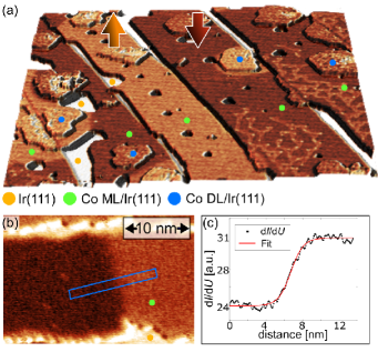
Fig. 1(b) shows a d/d map of a DW on a ML Co stripe, which separates oppositely magnetized out-of-plane domains, and the signal is plotted in Fig. 1(c) as a function of the position across the wall. The DW profile is fitted according to
| (1) |
where and are the spin averaged and spin-polarized contributions to the signals, respectively, is the center of the DW, and is the wall width. We fitted 8 walls from different samples, obtaining an average of , where the uncertainty represents the standard deviation of the values.
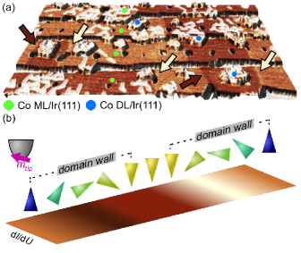
While Fig. 1(b) shows a DW imaged using a fully out-of-plane magnetic tip, Fig. 2(a) shows several DWs observed with a canted magnetic tip, which also has a significant in-plane component of the magnetization. With such a tip the DWs appear as bright or dark stripes depending on the magnetization direction within the walls. We find a correlation of the magnetization within a wall with the order of the out-of-plane orientation of the domains they separate, as indicated by the differently colorized arrows in Fig. 2(a)). This strict sequence of spin-resolved d/d contrasts demonstrates that the DWs in the Co ML on Ir(111) have a unique rotational sense, as sketched in Fig. 2(b). This is confirmed by investigating 13 independent DWs with the same magnetic tip (not shown). We conclude that the interfacial DMI is large enough to select a unique rotational sense and propose that it also induces Néel-type DWs according to the symmetry selection rules Heide et al. (2008); Thiaville et al. (2012); von Bergmann et al. (2014). An attempt to measure the absolute rotational sense of the DWs is presented in the Supplemental Material Sup .
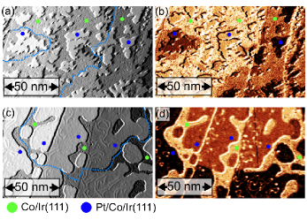
To investigate the effect on the DWs when the Co is sandwiched between Pt and Ir, we performed additional measurements on ML Pt islands on top of an almost complete ML of Co on Ir(111). Fig. 3(a) shows pseudomorphic Pt islands with irregular shapes grown with the Co/Ir(111) held at room temperature. The spin-resolved d/d contrast of the Pt islands in Fig. 3(b) is strongly correlated with that of the surrounding Co ML, and we conclude that the Co induces a magnetic polarization in the Pt and that the Pt/Co atomic bilayer is also out-of-plane ferromagnetic. A closer look to the data in Fig. 3(b) reveals two slightly different d/d contrast levels for each magnetization direction, originating from islands grown in the two different stackings. In order to obtain more extended films of Pt, we post-annealed the samples at moderate temperature ( C) after the Pt deposition. This results in a mostly fcc-stacked Pt layer attached to step edges as shown in Fig. 3(c). The magnetic domain structure of this sample is evident from the simultaneously aquired d/d map in Fig. 3(d). The Pt layer still presents out-of-plane magnetization, induced by the Co ML (see Fig. 3(d)). A close analysis of the position of the DWs for these two differently prepared samples, see blue lines in Figs. 3(b) and 3(d), demonstrates that the DWs tend to avoid the Pt/Co layer if possible, increasing their length in order to remain on the bare Co. This suggests a higher domain wall energy in the Pt/Co bilayer than in the Co ML on Ir(111). We were able to extract the width of only 2 DWs in the Pt/Co layer, due to their tendency to sit in very small constrictions, obtaining the values of 2.7 and 3.6 nm, similar to the ones in Co/Ir(111). To minimize the effect of the constriction size on the DW width Bruno (1999), we have selected walls occurring in areas at least twice as large as .
| System | ||||||
|---|---|---|---|---|---|---|
| Co/Ir(111) | ||||||
| Pt/Co/Ir(111) | ||||||
| Pt/Co/Co/Ir(111) |
To investigate the effects of the Pt/Co and Co/Ir interfaces on the total DMI, we have performed density functional theory (DFT) calculations. We apply the full-potential linearized augmented plane wave method (FLAPW) Wimmer et al. (1981); Jansen and Freeman (1984) as implemented in the FLEUR code FLE . We have performed structural relaxations for films of Co/Ir(111) and Pt/Co/Ir(111), where both Co and Pt are single atomic layers, and have considered fcc stackings of Co and Pt based on the experimental observations. For both systems we calculated the energy dispersion of homogeneous, flat spin spirals Kurz et al. (2004); Zimmermann et al. (2014) along the high symmetry directions – and – of the two dimensional Brillouin zone. To obtain the DMI, we calculated the energy contribution due to DMI in first order perturbation for every value of of the energy dispersion Zimmermann et al. (2014); Heide et al. (2009); Meyer et al. (2017) (see Supplemental Material for computational details Sup ).
We restrict ourselves to the region around the -point and use the nearest-neighbor approximation for exchange and DMI, which are expressed by the parameters and , respectively. The magnetocrystalline anisotropy energy (MAE) is obtained by constraining the spin quantization axis in out-of-plane () and in-plane () directions with respect to the film, determining the uniaxial anisotropy via .
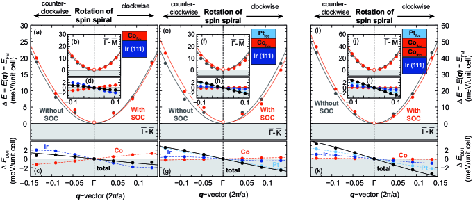
Figs. 4(a) and 4(b) show the calculated energy dispersion for Co/Ir(111) in - and - directions, respectively. The ferromagnetic (FM) state is the lowest in energy and the nearest-neighbor exchange interaction (Tab. 1) describes very well the energy dispersion. is small compared to the variation of the exchange (cf. in Tab. 1). The interfacial DMI results as the sum of the individual contributions from the different layers (see Fig. 4(c) and 4(d)), and it prefers clockwise rotating spin spirals (). The Ir surface dominates the total DMI, however Co has a significant contribution of opposite sign, which we attribute to its small coordination number Meyer et al. (2017). The MAE prefers an out-of-plane magnetization ( = , cf. Tab. 1), that favors collinear states over spin spirals.
An atomic Pt overlayer does not modify the exchange interaction significantly with respect to Co/Ir(111) (see Figs. 4(e), 4(f) and Tab. 1). In contrast, the MAE increases by about 50% and the total DMI is more than twice larger, as expected from an additive DMI effect due to the two interfaces with Pt and Ir Moreau-Luchaire et al. (2016). However, Figs. 4(g) and 4(h) show that the DMI is dominated by the contribution from the Pt overlayer. The Ir substrate has a minor contribution which is nearly quenched compared to its value in Co/Ir(111) (cf. Fig. 4(c)).
Adding another Pt adlayer does not change significantly the total DMI nor the contributions from the two interfaces (see Supplemental Material Sup ). We conclude that the hybridization of the Co layer with both the Ir and the Pt has a decisive impact on the resulting DMI. A simple additive effect as suggested in Ref. Moreau-Luchaire et al., 2016, where the Pt/Co and Co/Ir interfaces contribute with a similar DMI strength in a Pt/Co/Ir multilayer, does not apply for one atomic Co layer.
In order to test our interpretation, we have performed calculations with an additional Co layer, i.e. Pt/Co/Co/Ir(111) (cf. Figs. 4(i - l)). While the exchange rises by about 10%, the MAE is reduced by a factor of 10 compared to Pt/Co/Ir(111) (see Tab. 1). The total DMI increases compared to the Co ML system, because of an enhanced Ir contribution, whereas the Pt contribution is similar to the one in Pt/Co/Ir(111). Thus for a Co double layer both the Pt/Co and Co/Ir interfaces, which are farther apart from each other, contribute significanlty to the total DMI, supporting the interpretation of an additive DMI effect of Ref. Moreau-Luchaire et al., 2016. Note that the value of given in Tab. 1 for Pt/Co/Co/Ir(111) is still smaller than for Pt/Co/Ir(111) since it is given per Co atom.
The DW width and energy obtained with the DFT values of exchange, DMI, and MAE are given in Tab. 1. The DW widths obtained for Co/Ir(111) and Pt/Co/Ir(111) are in good agreement with the experimental values. Consistent with the spin spiral energy dispersions and the experimental observations, DWs are energetically unfavorable () for Co/Ir(111) and Pt/Co/Ir(111). The smaller DW energy in Pt/Co/Ir(111) seems to disagree with the experimental observation of DWs being more likely to occur on the Co ML. However, the difference between the two DW energies is small with respect to the accuracy of the parameters (see Supplemental Material for details Sup ).
In conclusion, we have combined SP-STM measurements and DFT calculations to investigate DWs and interfacial DMI on pseudomorphic Co/Ir(111) and Pt/Co/Ir(111) ultrathin films. We observe DMI-stabilized Néel walls with a fixed rotational sense, separating out-of-plane magnetic domains. Our calculations show a clockwise sense of magnetization rotation across the walls. The DMI increases by more than a factor of two in the sandwich structure. However, this increase is dominated by Pt with a negligible Ir contribution. For a Co double layer between Pt and Ir both interfaces contribute significantly to the total DMI. This highlights the importance of interlayer hybridization and Co film thickness in determining the total value of the DMI in magnetic multilayers.
Acknowledgements.
We gratefully acknowledge computing time at the supercomputer of the North-German Supercomputing Alliance (HLRN). This project has received funding from the European Unions Horizon 2020 research and innovation programme under grant agreement No 665095 (FET-Open project MAGicSky), and from the DFG via SFB668-A8.References
- Parkin et al. (2008) S. S. P. Parkin, M. Hayashi, and L. Thomas, Science 320, 190 (2008).
- Fert et al. (2013) A. Fert, V. Cros, and J. Sampaio, Nat. Nano. 8, 152 (2013).
- Moreau-Luchaire et al. (2016) C. Moreau-Luchaire, C. Moutafis, N. Reyren, J. Sampaio, C. A. F. Vaz, N. Van Horne, K. Bouzehouane, K. Garcia, C. Deranlot, P. Warnicke, P. Wohlhüter, J.-M. George, M. Weigand, J. Raabe, V. Cros, and A. Fert, Nat. Nano. 11, 444 (2016).
- Boulle et al. (2016) O. Boulle, J. Vogel, H. Yang, S. Pizzini, D. de Souza Chaves, A. Locatelli, T. O. Menteş, A. Sala, L. D. Buda-Prejbeanu, O. Klein, M. Belmeguenai, Y. Roussigné, A. Stashkevich, S. M. Chérif, L. Aballe, M. Foerster, M. Chshiev, S. Auffret, I. M. Miron, and G. Gaudin, Nat. Nano. 11, 449 (2016).
- Pulecio et al. (2016) J. F. Pulecio, A. Hrabec, K. Zeissler, R. M. White, Y. Zhu, and C. H. Marrows, (2016), arXiv:1611.06869 .
- Soumyanarayanan et al. (2017) A. Soumyanarayanan, M. Raju, A. L. Gonzalez Oyarce, A. K. C. Tan, M.-Y. Im, A. P. Petrović, P. Ho, K. H. Khoo, M. Tran, C. K. Gan, F. Ernult, and C. Panagopoulos, Nat. Mat. 16, 898 (2017).
- Heinze et al. (2011) S. Heinze, K. von Bergmann, M. Menzel, J. Brede, A. Kubetzka, R. Wiesendanger, G. Bihlmayer, and S. Blügel, Nat. Phys. 7, 713 (2011).
- Bogdanov and Yablonskii (1989) A. Bogdanov and D. A. Yablonskii, Sov. Phys. JETP 68, 101 (1989).
- Bogdanov and Rößler (2001) A. N. Bogdanov and U. K. Rößler, Phys. Rev. Lett. 87, 037203 (2001).
- Dzyaloshinskii (1957) I. E. Dzyaloshinskii, Sov. Phys. JETP 5, 1259 (1957).
- Moriya (1960) T. Moriya, Phys. Rev. Lett. 4, 228 (1960).
- Crépieux and Lacroix (1998) A. Crépieux and C. Lacroix, J. Mag. Mag. Mat. 182, 341 (1998).
- Bode et al. (2007) M. Bode, M. Heide, K. von Bergmann, P. Ferriani, S. Heinze, G. Bihlmayer, A. Kubetzka, O. Pietzsch, S. Blügel, and R. Wiesendanger, Nature 447, 190 (2007).
- Heide et al. (2008) M. Heide, G. Bihlmayer, and S. Blügel, Phys. Rev. B 78, 140403 (2008).
- Thiaville et al. (2012) A. Thiaville, S. Rohart, É. Jué, V. Cros, and A. Fert, EPL (Europhys. Lett.) 100, 57002 (2012).
- Romming et al. (2013) N. Romming, C. Hanneken, M. Menzel, J. E. Bickel, B. Wolter, K. von Bergmann, A. Kubetzka, and R. Wiesendanger, Science 341, 636 (2013).
- Fert (1990) A. Fert, Materials Science Forum 59-60, 439 (1990).
- Wells et al. (2017) A. W. J. Wells, P. M. Shepley, C. H. Marrows, and T. A. Moore, Phys. Rev. B 95, 054428 (2017).
- Dupé et al. (2016) B. Dupé, G. Bihlmayer, M. Böttcher, S. Blügel, and S. Heinze, Nat. Comm. 7, 11779 (2016).
- Dupé et al. (2014) B. Dupé, M. Hoffmann, C. Paillard, and S. Heinze, Nat. Comm. 5, 4030 (2014).
- Yang et al. (2015) H. Yang, A. Thiaville, S. Rohart, A. Fert, and M. Chshiev, Phys. Rev. Lett. 115, 267210 (2015).
- Vida et al. (2016) G. J. Vida, E. Simon, L. Rózsa, K. Palotás, and L. Szunyogh, Phys. Rev. B 94, 214422 (2016).
- Yang et al. (2016) H. Yang, O. Boulle, V. Cros, A. Fert, and M. Chshiev, (2016), arXiv:1603.01847 .
- Chen et al. (2015) G. Chen, A. T. N’Diaye, Y. Wu, and A. K. Schmid, App. Phys. Lett. 106, 062402 (2015).
- Corredor et al. (2017) E. C. Corredor, S. Kuhrau, F. Kloodt-Twesten, R. Frömter, and H. P. Oepen, Phys. Rev. B 96, 060410 (2017).
- Meckler et al. (2009) S. Meckler, N. Mikuszeit, A. Preßler, E. Y. Vedmedenko, O. Pietzsch, and R. Wiesendanger, Phys. Rev. Lett. 103, 157201 (2009).
- Hrabec et al. (2014) A. Hrabec, N. A. Porter, A. Wells, M. J. Benitez, G. Burnell, S. McVitie, D. McGrouther, T. A. Moore, and C. H. Marrows, Phys. Rev. B 90, 020402 (2014).
- Bickel et al. (2011) J. E. Bickel, F. Meier, J. Brede, A. Kubetzka, K. von Bergmann, and R. Wiesendanger, Phys. Rev. B 84, 054454 (2011).
- (29) See Supplemental Material.
- von Bergmann et al. (2014) K. von Bergmann, A. Kubetzka, O. Pietzsch, and R. Wiesendanger, J. Phys.: Condensed Matter 26, 394002 (2014).
- Bruno (1999) P. Bruno, Phys. Rev. Lett. 83, 2425 (1999).
- Wimmer et al. (1981) E. Wimmer, H. Krakauer, M. Weinert, and A. J. Freeman, Phys. Rev. B 24, 864 (1981).
- Jansen and Freeman (1984) H. J. F. Jansen and A. J. Freeman, Phys. Rev. B 30, 561 (1984).
- (34) www.flapw.de.
- Kurz et al. (2004) P. Kurz, F. Förster, L. Nordström, G. Bihlmayer, and S. Blügel, Phys. Rev. B 69, 024415 (2004).
- Zimmermann et al. (2014) B. Zimmermann, M. Heide, G. Bihlmayer, and S. Blügel, Phys. Rev. B 90, 115427 (2014).
- Heide et al. (2009) M. Heide, G. Bihlmayer, and S. Blügel, Phys. B 404, 2678 (2009).
- Meyer et al. (2017) S. Meyer, B. Dupé, P. Ferriani, and S. Heinze, Phys. Rev. B 96, 094408 (2017).