Simulation of deflecting structures for dielectric laser driven accelerators
Abstract
In laser illuminated dielectric accelerators (DLA) high acceleration gradients can be achieved, due to high damage thresholds of the materials at optical frequencies. This is a necessity in developing more compact particle accelerator technologies. The Accelerator on a CHip International Program funded by the Gordon and Betty Moore Foundation is researching such devices. Means to manipulate the beam, i.e. focusing and deflection, are needed for the proper operation of such devices. These means should rely on the same technologies for manufacturing and powering like the accelerating structures. In this study different concepts for dielectric laser driven deflecting structures are investigated via particle-in-cell (PIC) simulations and compared afterwards. The comparison is conducted with respect to the suitability for beam manipulation. Another interesting application will be investigated as a diagnostic device for ultra short electron bunches from conventional accelerators functioning like a radio frequency transverse deflecting cavity (TDS).
keywords:
dielectric laser accelerator , PIC , transverse deflecting structures , ACHIP1 Introduction
The Accelerator on a CHip International Program (ACHIP) is a research project funded by the Gordon and Betty Moore Foundation. It aims at the construction of a compact fully laser driven electron accelerator for radiation generation and atto-second science. Several universities in Europe and the USA and the national laboratories PSI, DESY and SLAC are involved. [1]
This research field gains more attention in recent years as the search for compact particle acceleration technologies continues. Fully dielectric laser driven acceleration structures are foreseen to sustain high acceleration gradients in the regime. This is mainly due to the high laser damage thresholds of dielectrics at optical frequencies. The advancement in micro- and nano-fabrication from the semi conductor industry can be leveraged in the manufacturing of these structures limiting production costs. Also the ongoing development in laser technologies is promising.[2]
Structures for focusing and deflection of the beam are necessary for the eventual implementation of such an accelerator. Deflecting structures also can be useful diagnostics for short electron bunches. In this paper three candidates for the deflection of particles are investigated via PIC simulation.
2 Grating based dielectric laser acceleration
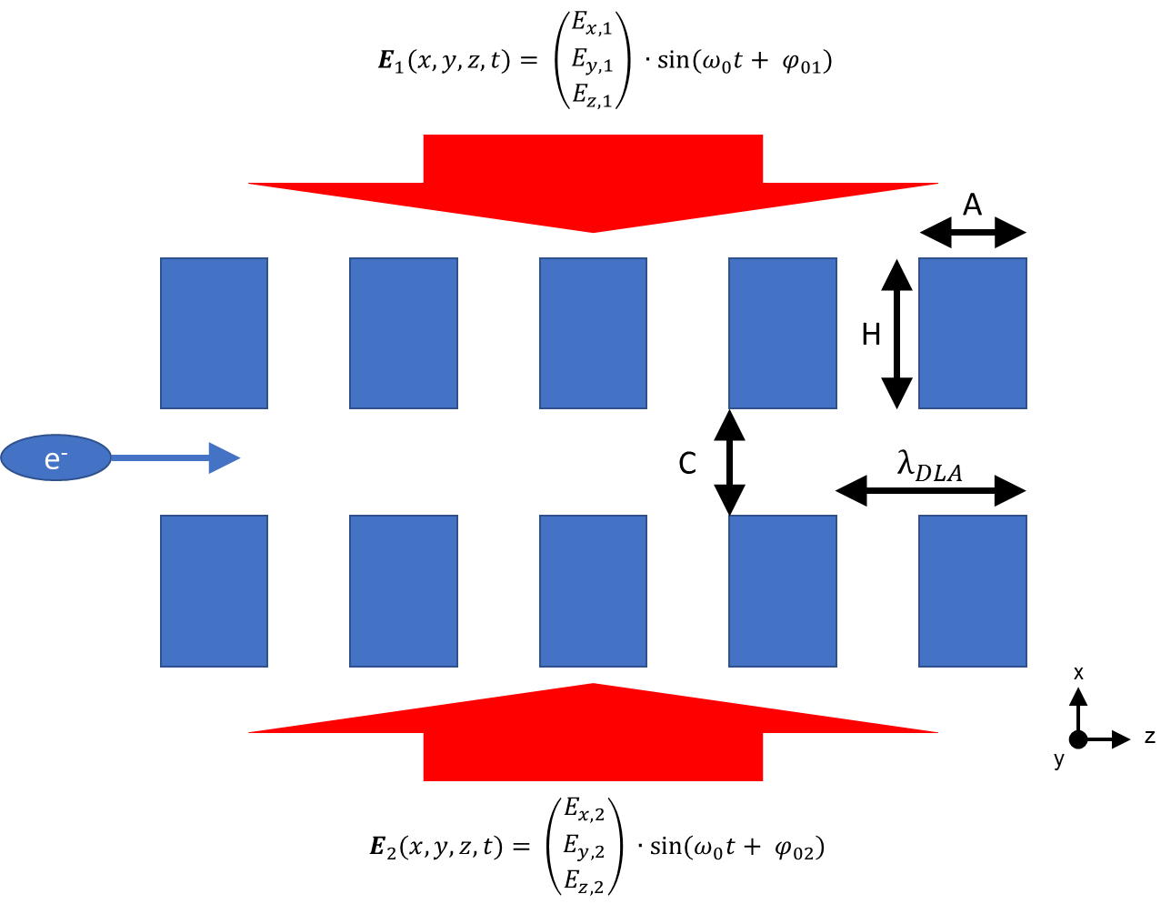
The investigated structure consists of two gratings with a gap. They are illuminated form both sides with laser beams. The laser beams are in phase and have the same amplitude. Electric fields of both beams are polarized in the direction the electron beam travels along the gap. Figure 1 is illustrating the structure.
The periodic diffraction fields in the gap along the z-axis can be described via spatial harmonics. If the grating period matches the incoming laser wavelength, the first spatial harmonic has a speed of light phase velocity. The acceleration in this harmonic is transversely uniform depending on the gap size. The phase velocity of this first spatial harmonic can be reduced by shortening the grating period with respect to the laser wavelength making it possible to also accelerate non-relativistic particles. Alternatively higher order modes can be chosen to be synchronous with the particle according to this synchronicity condition:
| (1) |
Where n is the order of the spatial harmonic, is the fraction of the vacuum speed of light of the particle, is the central wavelength of the incoming laser field and gives the period of the grating structure.
3 Grating based deflecting structures
The presented structures are grating based due to the necessary compatibility with the grating type accelerator design. For acceleration the electric field of the incoming laser is linearly polarized in longitudinal direction of the electron beam.
In the first investigated scheme (A) the polarization is rotated into the y-direction transverse to the e-beam. The deflection now should occur in the “free” direction not limited by the grating aperture .
For the second scheme (B) the phase of the two incoming beams is set off by canceling out the accelerating fields and amplifying the transverse components. Here the deflection appears in the direction limited by the grating (See figure 1 and table 1).
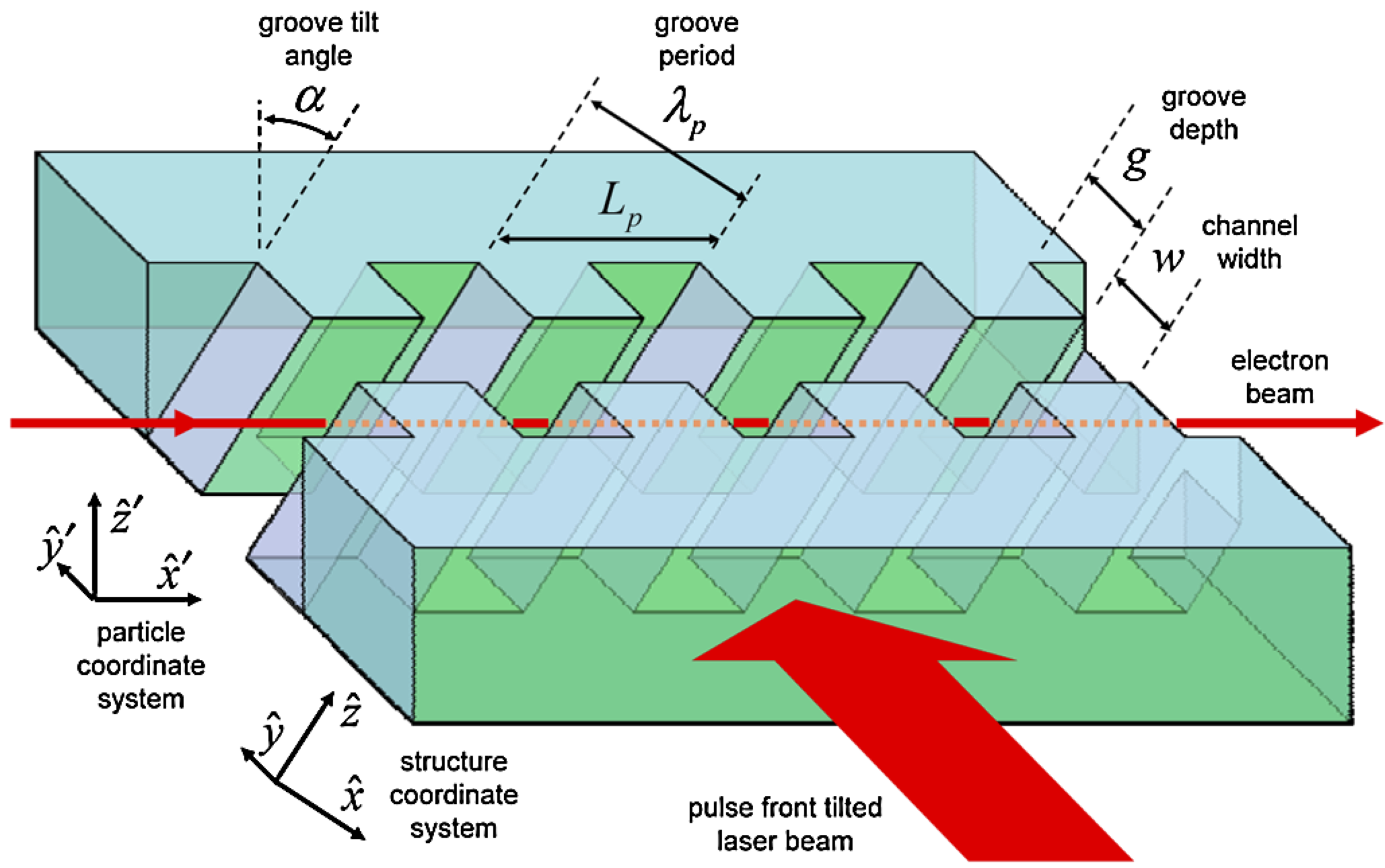
The third scheme (C) is from [3] and a rotation of the whole acceleration structure so that the force has an additional strong transverse component as shown in figure 2. The polarization of the electric field of the laser is still perpendicular to the direction of the grating groves. The other component is still in the longitudinal direction and will induce additional energy spread if used as streaking device.
| E-Field | Accelerator | Scheme A | Scheme B |
|---|---|---|---|
| 0 | 0 | 0 | |
| 0 | 0 | ||
| 0 | |||
| 0 | 0 | 0 | |
| 0 | 0 | ||
| 0 | |||
| 0 | 0 |
4 PIC simulation
The CST PIC [4] simulations were set up with the parameters from table 2 for one grating period with a point source test beam and excited by plane wave. The deflection is laser-to-electron phase dependent and the maximum is shown in table 3. The dimensions of the grating used in the simulation are shown in figure 1.
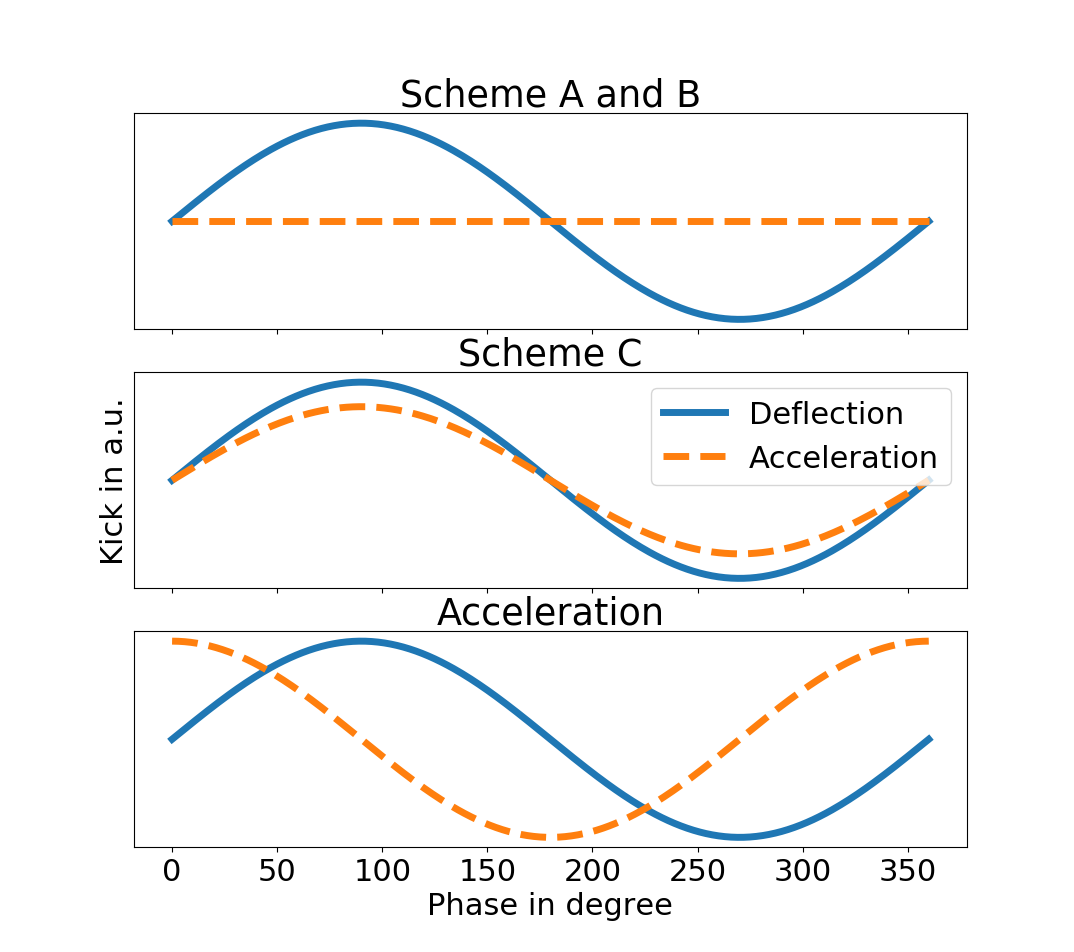
Additionally the transverse kick from the acceleration structure is investigated as comparison. It is important to note that this kick is position dependent and particles at the center of the gap are not kicked. This is comparable to a focusing or defocusing of an electron beam. Here the offset for the test beam is from the gap center.
| Parameter | Value |
|---|---|
| Wavelength | |
| Laser Amplitude | |
| Particle Energy |
| Scheme | A | B | C | Accel. |
|---|---|---|---|---|
| Max. defl. | ||||
| Defl. plane | unlimited | limited | unlimited | focusing |
5 Results
The results show that the schemes B and C may be feasible candidates for deflection or streaking devices. In scheme B the beam size is limited by the aperture of the structure which limits the resolution in a streaking application. For beam manipulation the scheme may still be feasible. Scheme C has the strongest deflection forces but inherently has longitudinal forces in the sam order of magnitude, too, which would add to the energy spread of the streaked particles. Both schemes have transverse forces an order of magnitude stronger than the focusing/defocusing forces of the acceleration structure. Scheme A has only limited deflection forces. The electric field and the effect of the magnetic field are canceling each other out. In figure 3 the relations for the different schemes are shown.
6 Outlook and Conclusion
Due to the dependence of the deflecting force on the laser-to-electron phase and the short laser wavelength in use further investigation is necessary to study the beam dynamics in such a system. Results on that topic can be found in [5]. For use as a streaking device the maximum bunch length is limited to one quarter of the driving wavelength. With the equation from [6] for the longitudinal TDS resolution for electrons at optimal phase advance to the detector screen
| (2) |
one can see that a large beta function at the TDS () is beneficial for the longitudinal resolution. The limited beta function due to the smaller apertures of DLA can be compensated by the high frequency () of the incoming fields. The high intensities achievable lead to a high streaking voltage . The remaining quantities are the transverse emittance , the elementary charge and the particle momentum . Schemes A and C streak in the direction of the DLA which is not limited by the gap size. Here a bigger beta function might be achievable. Within this limitations a longitudinal resolution in the attosecond regime would be theoretically possible with these grating type structures.
7 Acknowledgments
This research was conducted under the Accelerator on a CHip International Program (ACHIP) funded by the Gordon and Betty Moore Foundation via grant GBMF4744.
References
References
- et. al. [2017a] Rasmus Ischebeck et. al. The accelerator-on-a-chip international program. NIMA Proceedings, 2017a.
- England et al. [2014] R Joel England, Robert J Noble, Karl Bane, David H Dowell, Cho-Kuen Ng, James E Spencer, Sami Tantawi, Ziran Wu, Robert L Byer, Edgar Peralta, et al. Dielectric laser accelerators. Reviews of Modern Physics, 86(4):1337, 2014.
- et. al. [2009] T. Plettner et. al. Photonic-based laser driven electron beam deflection and focusing structures. Phys. Rev. ST Accel. Beams, 2009.
- [4] Cst. URL https://www.cst.com/.
- et. al. [2017b] Frank Mayet et. al. Using short drive laser pulses to achieve net focusing forces in tailored dual grating dielectric structures. NIMA Proceedings, 2017b.
- Röhrs et al. [2009] Michael Röhrs, Christopher Gerth, Holger Schlarb, Bernhard Schmidt, and Peter Schmüser. Time-resolved electron beam phase space tomography at a soft x-ray free-electron laser. Phys. Rev. ST Accel. Beams, 12:050704, May 2009. doi: 10.1103/PhysRevSTAB.12.050704. URL https://link.aps.org/doi/10.1103/PhysRevSTAB.12.050704.