Flux Rope Breaking and Formation of a Rotating Blowout Jet
Abstract
We analyzed a small flux rope eruption converted into a helical blowout jet in a fan-spine configuration using multi–wavelength observations taken by SDO, which occurred near the limb on 2016 January 9. In our study, first, we estimated the fan–spine magnetic configuration with the potential field calculation and found a sinistral small filament inside it. The filament along with the flux rope erupted upward and interacted with the surrounding fan-spine magnetic configuration, where the flux rope breaks in the middle section. We observed compact brightening, flare ribbons and post-flare loops underneath the erupting filament. The northern section of the flux rope reconnected with the surrounding positive polarity, while the southern section straightened. Next, we observed the untwisting motion of the southern leg, which was transformed into a rotating helical blowout jet. The sign of the helicity of the mini–filament matches the one of the rotating jet. This is consistent with the jet models presented by Adams et al. (2014) and Sterling et al. (2015). We focused on the fine thread structure of the rotating jet and traced three blobs with the speed of 60–120 , while the radial speed of the jet is 400 . The untwisting motion of the jet accelerated plasma upward along the collimated outer spine field lines, and it finally evolved into a narrow coronal mass ejection at the height of . On the basis of detailed analysis, we discussed clear evidence of the scenario of the breaking of the flux rope and the formation of the helical blowout jet in the fan-spine magnetic configuration.
keywords:
Sun:activity – Sun:magnetic fields – Sun:filament, Prominences – Sun:coronal mass ejections (CMEs)1 Introduction
Solar jets are transient plasma ejections from the lower solar atmosphere to the upper corona. They are observed in various spatial, temporal scales and wavelengths, e.g., spicules (Sterling, 2000; Sterling et al., 2010; Adams et al., 2014), chromospheric jets (Shibata et al., 2007; Katsukawa et al., 2007; Nishizuka et al., 2008, 2011; Singh et al., 2011), H surges (Schmieder et al., 1995; Uddin et al., 2012), ultraviolet/extreme ultraviolet (UV/EUV) jets (Alexander & Fletcher, 1999; Joshi et al., 2017), X-ray jets (Shibata et al., 1992; Cirtain et al., 2007) and white light jets (Wang & Sheeley, 2002). Jets are observed both in active regions (Shimojo et al., 1998; Schmieder et al., 2013; Filippov et al., 2013; Joshi et al., 2015), and in coronal holes (Savcheva et al., 2007; Young & Muglach, 2014; Sterling et al., 2015). At present, two different models are proposed to explain the jet formation: the standard jet model (Shibata et al., 1992) and the blowout jet model Moore et al. (2010). The second one is extended from the first one.
In the standard jet model, an emerging flux triggers a jet by magnetic reconnection with the ambient open magnetic field both in an active region and in a coronal hole, and compact bright flare loops are formed at the edge of the jet base This scenario is supported by several observations and numerical simulations (e.g., Shibata et al., 1992; Yokoyama & Shibata, 1995, 1996; Shimojo et al., 2001; Moreno-Insertis et al., 2008; Nishizuka et al., 2008; Archontis et al., 2010). Flux cancellation is sometimes discussed as an origin of magnetic reconnection between anti-parallel magnetic fields, instead of the emerging flux (Chifor et al., 2008a; Chifor et al., 2008b). In the blowout jet model proposed by Moore et al. (2010), an emerging flux triggers a jet in a magnetic configuration with a sheared core flux, leading to the core flux or filament eruption (see also Liu et al., 2011; Young & Muglach, 2014). Furthermore, Adams et al. (2014) first deduced that the eruption of a mini-filament or a twisted flux rope, which is triggered by flux convergence or cancellation without a bipole emergence, is responsible for a blowout macrospicule jet in the coronal hole, and Sterling et al. (2015) first deduced the same model for all or nearly all blowout jets in coronal holes. Panesar et al. (2016) found that the same model fits blowout jets in non-coronal-hole regions such as quiet regions.
The blowout jets sometimes grow into small and narrow coronal mass ejections (CMEs) (Hong et al., 2011; Shen et al., 2012; Li et al., 2015). It is also found that a helical blowout jet is originated from a twisted filament (Hong et al., 2013; Moore et al., 2015; Filippov et al., 2015a). Various numerical simulations have been performed to understand the nature of helical blowout jets (Archontis et al., 2010; Moreno-Insertis & Galsgaard, 2013; Archontis & Hood, 2013; Pariat et al., 2015; Lee et al., 2015). A twisted flux rope is produced by the internal magnetic reconnection between sheared field lines in an emerging flux region (Archontis & Hood, 2013). The flux rope is stimulated to erupt by the kink or torus instability, leading the external reconnection (Moreno-Insertis & Galsgaard, 2013). This process produces a jet and the untwisting motion of the twisted flux tubes (Li et al., 2015). Pariat et al. (2015) considered another configuration of a fan-spine structure, which stored the energy of the shared field at a separatrix, and reproduced a helical jet via magnetic reconnection at the separatrix surface. The data-driven Magnetohydrodynamic (MHD) simulation also shows that the emerging flux near the fan-spine configuration can produce a helical jet (Cheung et al., 2015).
Historically, a helical motion was first found in macrospicules. They were observed with an EUV spectrometer. Their properties are high temperature height, fast flows at the speed of 80 , high density , brighter edges than the central region, and the broad emission line which narrows in the later phase (Pike & Harrison, 1997; Parenti et al., 2002). There are statistical studies of their properties (Yamauchi et al., 2005; Bennett & Erdélyi, 2015; Kiss et al., 2017). The horizontal unfolding motion of a twisted flux rope shows Doppler shifts on the limb, at the speed of 50-120 , in association with an independent radial flow of the jet (Pike & Mason, 1998; Scullion et al., 2009; Kamio et al., 2010). The helical motion is also discussed on the base of imaging observations (Canfield et al., 1996; Jiang et al., 2007; Patsourakos et al., 2008; Shen et al., 2011; Lee et al., 2013), as well as the coexistence of a macrospicule and a blowout jet (Kayshap et al., 2013; Adams et al., 2014).
In this paper, we present a clear event of a helical blowout jet with the detailed analysis of its formation and initiation. We discuss the following questions in details: what is the origin of the rotation in blowout jets and how is the helicity transferred? In Section 2, we describe the observational dataset. In Section 3, we explain topologies of the filament and the surrounding magnetic field configuration. In Section 4, we present our observational analysis of the helical blowout jet and the associated CME. In Section 5, we summarize our results and discuss the origin of an untwisting motion of helical blowout jets.
2 Observational Data Set
We used observational data taken by the Atmospheric Imaging Assembly (AIA; Lemen et al., 2012) on board the Solar Dynamics Observatory (SDO; Pesnell et al., 2012). AIA takes full–disk images of the Sun with seven extreme ultraviolet (EUV), two ultraviolet (UV) and one continuum wavelength channels with the common spatial resolution of per pixel. The temporal resolutions of UV and EUV observations are 24 and 12 s, respectively. The time-series of EUV data taken with 304 Å and 171 Å filters of AIA/SDO are used to study a mini–filament eruption and an associated jet, in addition to H data taken by the National Solar Observatory-Global Oscillation Network Group (NSO-GONG). We used the line–of–sight (LOS) magnetograms taken by the Helioseismic and Magnetic Imager (HMI; Schou et al., 2012) on board SDO. It provides the photospheric magnetic field data with the resolution of per pixel with a minimum cadence of 45 s.
White light data is taken by the Large Angle and Spectrometric Coronagraph (LASCO; Brueckner et al., 1995), which consists of three coronagraphs C1, C2, and C3, on board the Solar and Heliospheric Observatory (SOHO). We used the white light coronagraph data of C2 and C3.
3 Magnetic Topology of the Filament and the Surrounding Field
3.1 Initial Magnetic Configuration of the H mini-filament and the Ambient Coronal Field
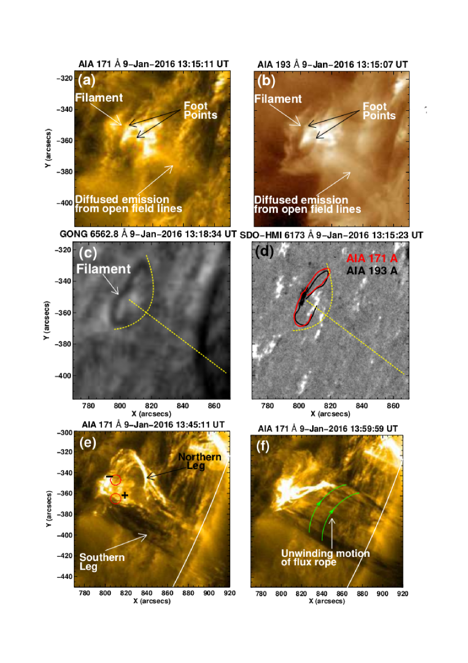
Figure 1 shows snapshot images of a mini-filament near the west limb on 2016 January 9, the magnetic field at the footpoint of the filament, and its time evolution. Figures 1(a)–(b) represent a dark mini-filament taken with the AIA 171 Å and 193 Å filters at 13:15 UT, while Figure 1(c) shows a corresponding H filament taken by GONG/NSO. The mini–filament is elongated from the northwest to the southeast. The magnetic field in the same area taken by HMI/SDO is shown in Figure 1(d).
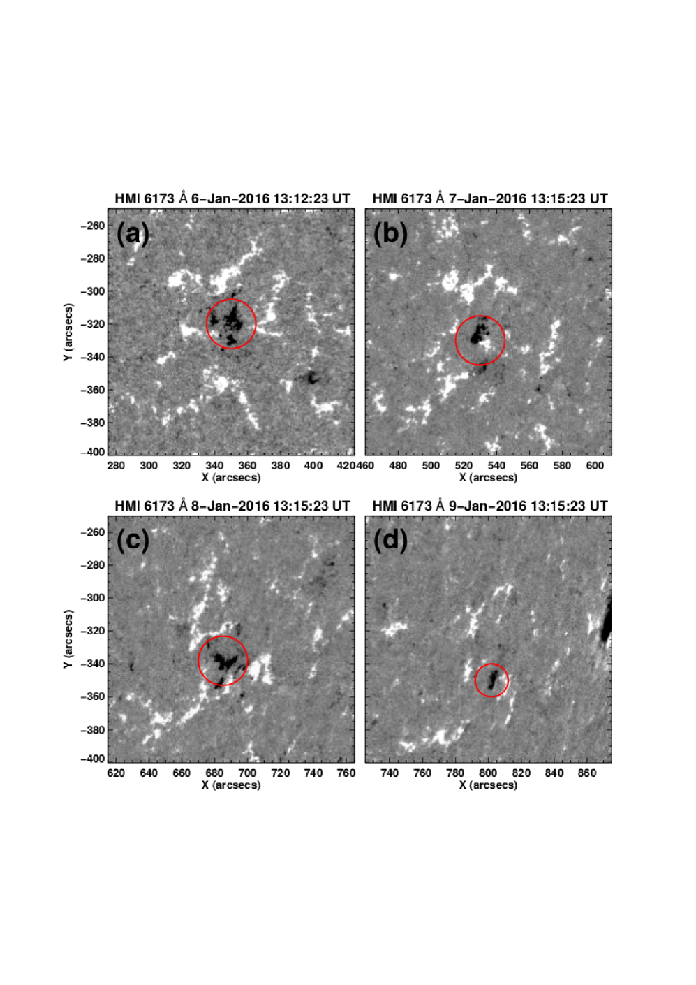
The filament was close to the limb on January 9, where the photospheric magnetic field measurement is obscure due to the projection effect. Figure 2 represents snapshots of the line-of-sight magnetograms taken by HMI/SDO during 2016 January 6–9. During the period, we found a patch of the negative polarity surrounded by the positive polarity, and the overall photospheric magnetic field structure is kept almost the same.
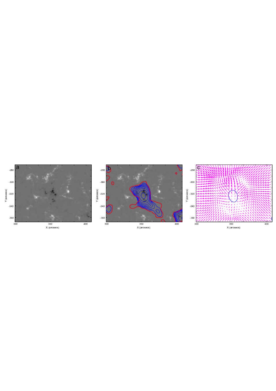
To calculate the potential magnetic field above the region, we used the magnetogram at 13:12 UT on 2016 January 6 (Figure 3(a)). For potential-field calculations, we used the Green function method to solve numerically the Neuman external boundary value problem (see Filippov & Den, 2001; Filippov et al., 2013). This method is most preferable for the extrapolation of the photospheric magnetic field within a restricted region into the corona. Figure 3(b) shows polarity inversion lines (PILs) at different heights. The red contours present the PIL at the height of 1.5 Mm, while the blue contours present the PIL at heights from 3 Mm to 15 Mm, with the step of 1.5 Mm. Above the height of 15 Mm, the field is upwardly directed everywhere, and a null point is located just below this height. Figure 3(c) shows the map of the horizontal magnetic field at the height of 13.5 Mm with the contour of the PIL. The 3D null point is located on the PIL and at the point where the horizontal magnetic field diverges and vanishes.
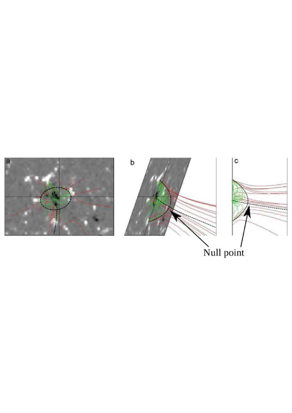
The potential field structure is shown in Figure 4 with different views. All the field lines emanating from the central negative polarity are connected to the surrounding positive polarity region with closed structure. Outside of this central area, all field lines are open. In a side view, it is found that the structure is a fan-spine configuration. The top of the dome which covers closed lines is at the height of about 13-15 Mm, which is higher than the estimated height of the mini filament.
3.2 Anchoring and Chirality of the Filament
We derived the filament shape from the AIA/SDO 171 Å and 193 Å images (Figures 1(a) and 1(b)) and over–plotted them on the magnetogram colored in red for 171 Å and in black for 193 Å(see Figure 1(d)). The northern footpoint of the filament is anchored in the negative polarity, while the southern footpoint is connected with the positive polarity. This anchoring is confirmed by AIA images of the mini-filament eruption at 13:45:11 UT, when the mini-filament is transformed into a jet (Figure 1(e)). Since only the leg anchored in the positive polarity can merge into the ambient positive flux and produce a jet into the corona, the southern leg connected to the jet should be anchored in the positive polarity. Accordingly, the northern leg is anchored in the negative polarity.
According to this anchoring, the axial magnetic field of the mini–filament is directed from the south to the north, i.e., leftward when it is viewed from the positive polarity (from the east). On the basis of the direction of the filament axial magnetic field, we identified the filament chirality to be sinistral. In flux rope models, sinistral filaments lie inside right–handed helical fields (Martin, 1998, 2003). During the rotating phase of the jet at 14:00 UT, we actually observed the unwinding of a right–handed helix of the flux rope (shown by green curved lines in Figure 1(f)) (see the section 4 for more details). The observed right–handed twist of the flux rope helix is consistent with its sinistral chirality. This case also seems to be in agreement with the general hemispheric chirality rule (Pevtsov et al., 2003).
4 Observational Analysis of the Jet Formation and Dynamics
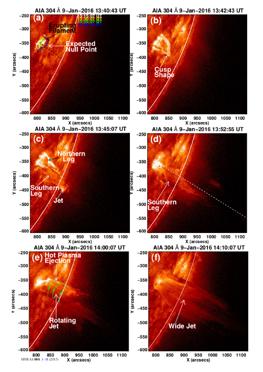
Figure 5 shows the snapshots of the helical blowout jet observed in the 304 Å channel of AIA on 2016 January 9. The mini–filament was observed for many hours before 13:15 UT. The mini–filament slowly rose upward at 13:34 UT. The filament approached to the magnetic null point, keeping its arch shape (shown by different colors for each step in Figure 5(a)). The fan–spine structure and the location of the magnetic null, which were estimated from the potential field calculation, are drawn in Figure 5(a). The filament continued to move upward up to 13:42 UT, when the arch shape changed into a cusp–like structure (Figure 5(b)).
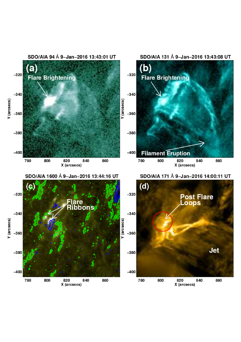
Figures 6(a) and 6(b) show the 94 Å and 131 Å images of AIA/SDO at around 13:43 UT. The 94 Å and 131 Å filter images represent hot plasma, and a compact brightening was observed just below the erupting filament. This compact brightening is stretched along a PIL, where the two–ribbon structure appeared at the same place in 1600 Å images (Figure 6(c)). One part of the two–ribbon structure was located in the positive polarity, while the other one in the negative polarity. Furthermore, in the later phase, post–flare loops were formed above the two–ribbon structure, which was observed in 171 Å images (Figure 6(d)). In the standard flare model, the two–ribbon structure is produced by the bombardment of the chromosphere by released electron beams from the magnetic reconnection point in the corona just below an erupting flux rope, and the post-flare loops are formed by the chromospheric evaporation after the bombardment (see CSHKP model: Carmichael (1964), Sturrock (1966), Hirayama (1974), Kopp & Pneuman (1976)). By analogy, we expect magnetic reconnection to occur below the erupting mini-filament, which released high energy particles and caused the compact brightening and the two-ribbon structure.
After 13:45 UT the ascending arch of the erupting filament seems to break into two semi-arches: with the southern and northern parts. The southern part with the footpoint anchored in the positive polarity proceeds ascending motion and transforms into a rotating column i.e., a jet. The magnetic field of this leg is upwardly directed, which is coincided with the direction of the ambient coronal field. Therefore, the internal field of this leg can easily merge into the ambient coronal field. The northern part of the filament stopped its ascending motion and began to move downward. Since the foot point of this leg is anchored in the negative polarity, its axial field becomes anti–parallel to the coronal field at the height above the fan surface. The field of the northern leg cannot be further stretched into the corona because antiparallel field lines should reconnect. It seems that the northern part of the filament found anchoring for the other footpoint in the nearby positive polarity (Figure 5(c)), forming an arch shape for a few minutes and then disappeared (see Figure 5(c) and attached movie). This arch shape is longer than the post-flare loops above the mini two-ribbon structure.
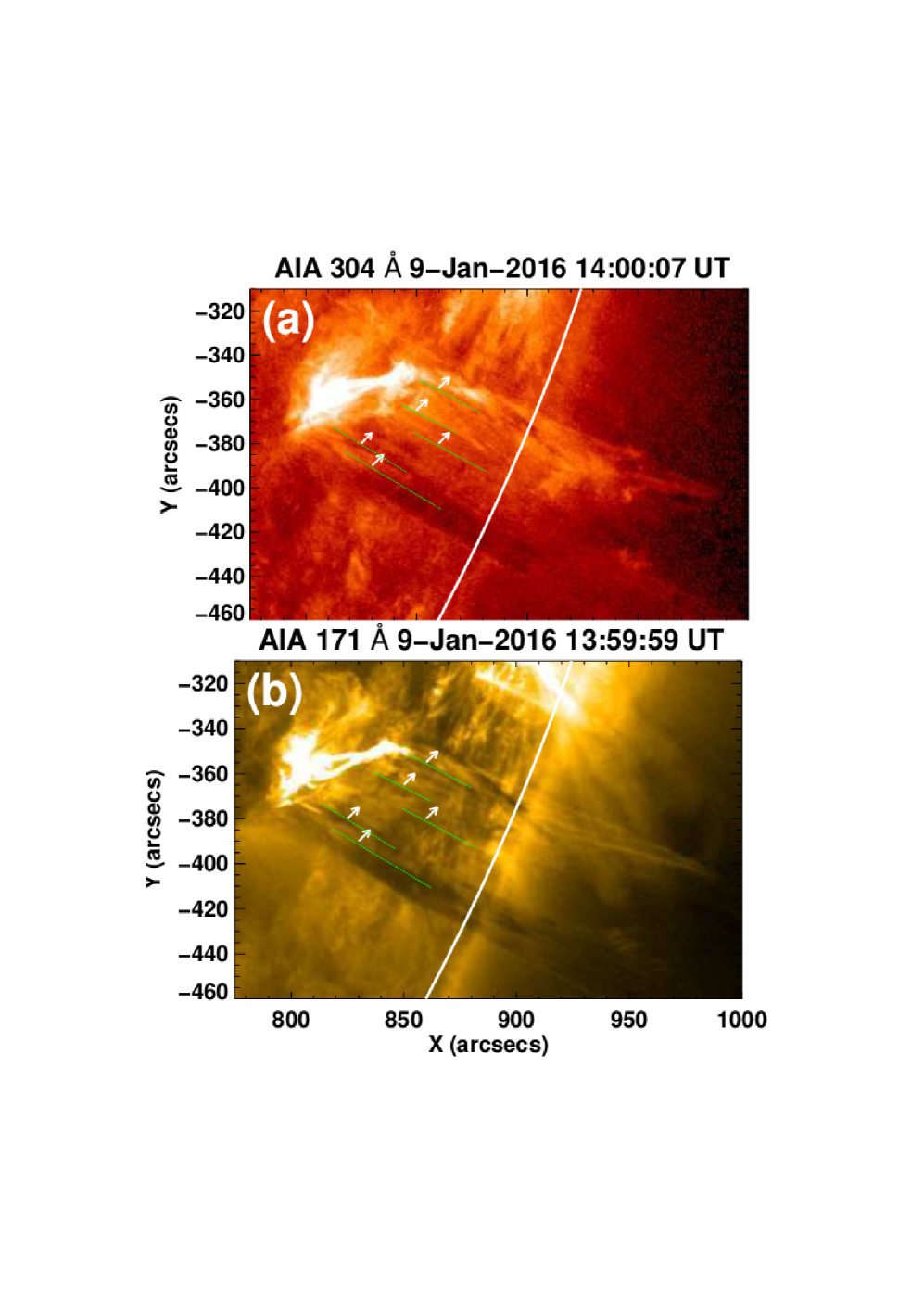
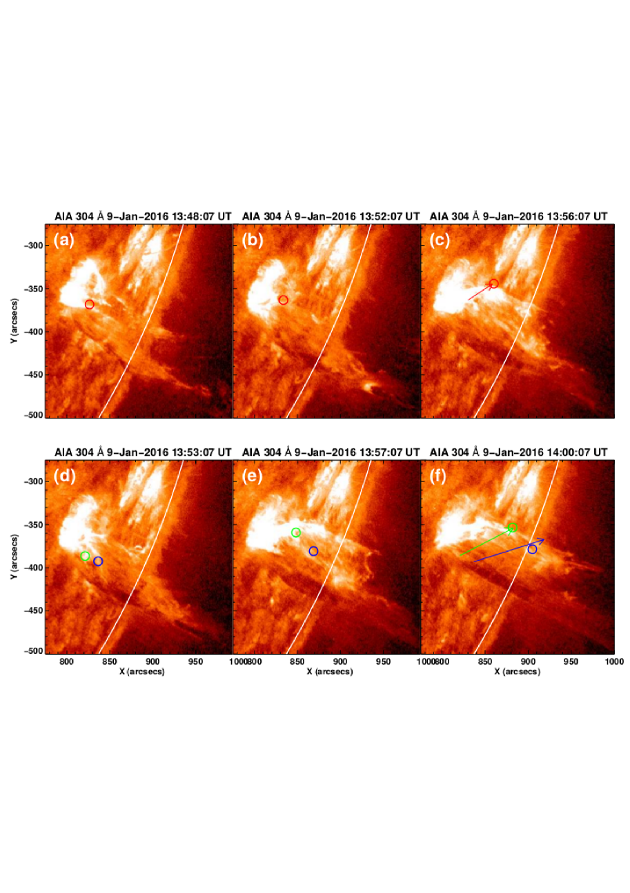
At 13:53 UT, the southern part of the filament stretched along the open collimated path is visible (Figure 5(d)). The rotational motion started at around 13:52 UT and ended at around 14:07 UT. The direction of the rotation is from the southwest to the northeast (when viewed on disk), and in other words, a clockwise rotation when viewed from the above. The direction of the rotation motion is represented by green arrows in Figure 5(e). Figure 7 shows zoom-up images of the fine structure of the rotating jet, observed with AIA 304 Å and 171 Å filters at 14:00 UT. We identified some fine dark threads moving as a whole from the southeast to the northwest on the front side of the jet. Five clear fine threads are marked by dotted green lines with their directions of motion by white arrows. At last, most of the threads became stretched radial (see also Figure 5(f)).
We also found a cusp-like hot plasma ejection from 13:53 UT to 13:58 UT, which lasted for a few minutes (Figure 5(e)). This is similar to a plasmoid ejections in solar flares (Shibata et al., 1994) and tiny plasmoid ejections in chromospheric jets (Singh et al., 2012). Another possibility is a corresponding structure of a propagating shock driven by magnetic reconnection and the associated velocity pulse, as proposed in spicules and macrospicules (e.g., Shibata & Suematsu, 1982; Kayshap et al., 2013).
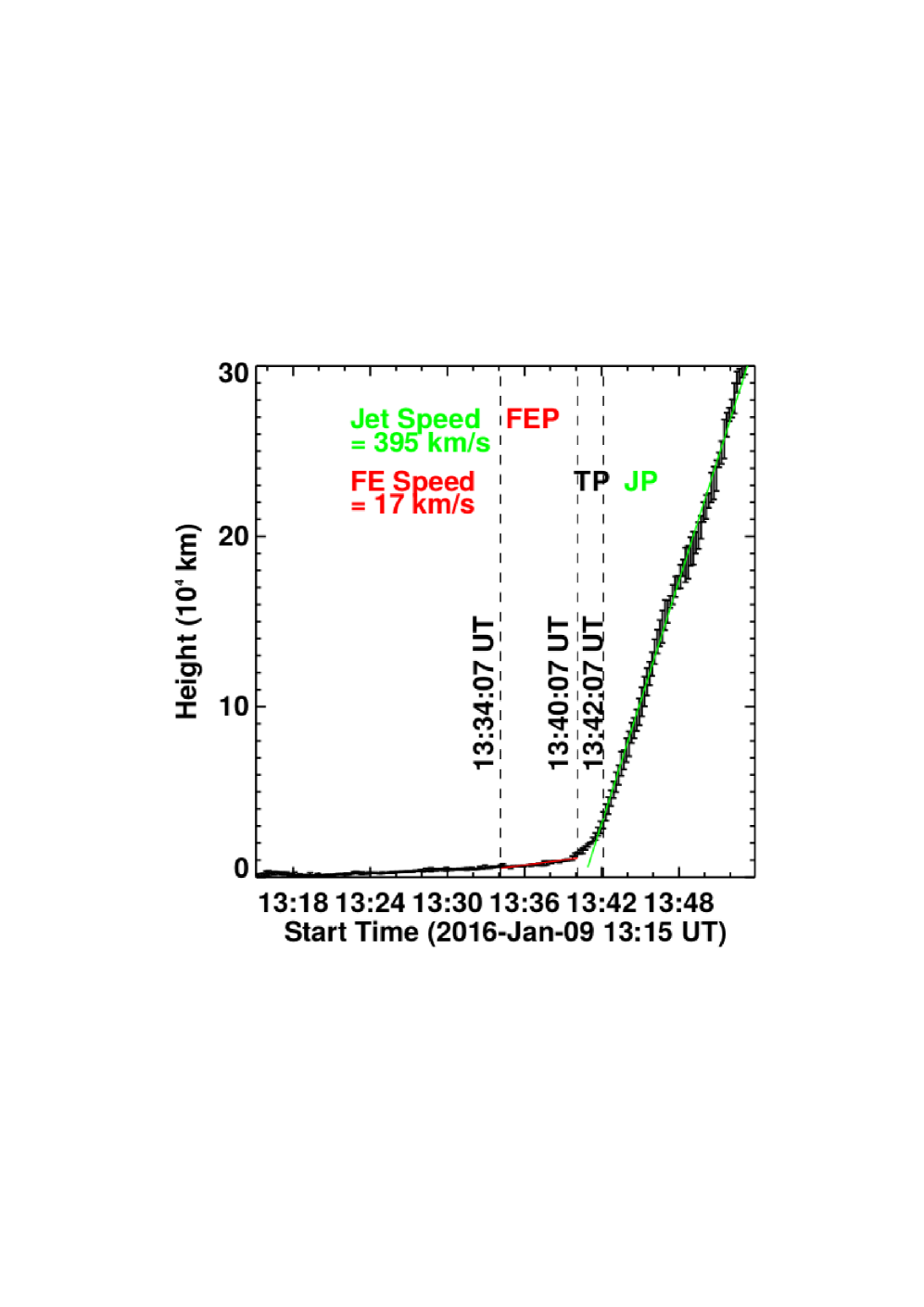
We measured the upward velocity of the filament and the jet from a height–time diagram (Figure 8). The slit is shown in Figure 5(d). We tracked the front edge of the erupting filament and the jet. The speed was calculated by the linear fitting. The profile shows the initial slow eruption of the filament with an average speed of 17 , during 13:34 UT–13:40 UT, and the acceleration to a higher speed of 395 during 13:42 UT–13:53 UT. The acceleration is synchronized with the transformation of the filament into the jet between 13:40 UT and 13:42 UT.
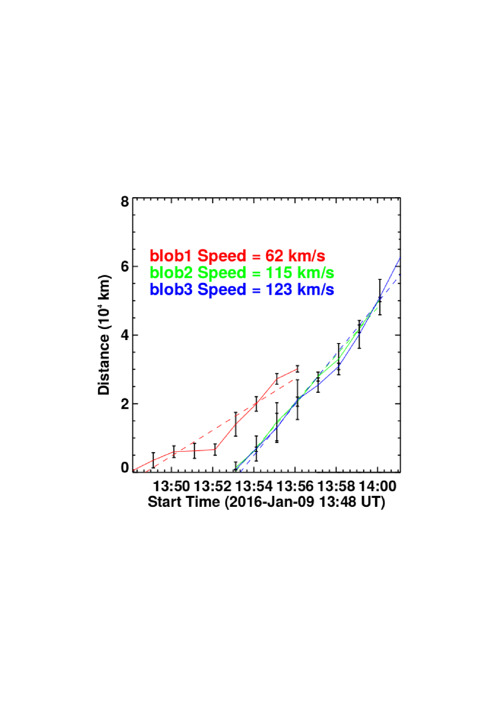
The rotation motion of the jet is analyzed in more detail in Figures 9 and 10. Figure 9 shows the images of AIA 304 Å from 13:48 UT to 14:00 UT. We tracked three small plasma blobs (or bright spots) moving in front of the jet axis from the southeast to the northwest. These three moving bright blobs are shown by the red, green and blue circles. The coordinates of the starting points are used as the reference points. Then we measured the distance between a reference point and a rotating blob at different times. To estimate the errors in the measurements, we repeated measurements three times for each blob and calculated the standard deviation of the three distances for an error. The distance-time diagrams of the three rotating blobs are shown in Figure 10. The linear fitting method was used to estimate the blob velocity. It is found that the different parts of the jet rotate with an average speed of 627 , 1153 , and 1236 . The estimated speeds include both horizontal and vertical motions because the blobs move both in the vertical and horizontal directions. These rotation speeds are much lower than the jet eruption speed.
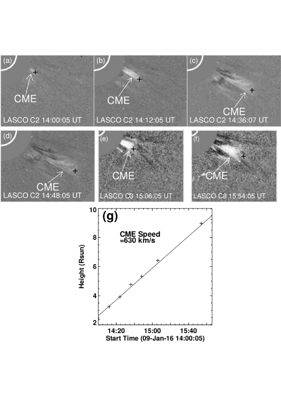
The jet was associated with a narrow CME (Figure 11). The CME was observed after 14:00 UT by the LASCO C2 coronagraph. The CME was narrow and collimated (Figure 11(b)). The width of the CME slightly increased with time (Figure 11(c)– 11(f)). The CME appeared in the LASCO C3 field of view at 15:06 UT (Figure 11(e)) and continued to move upward (Figure 11(f)). Figure 11(g) shows the height–time profile of the leading edge of the CME from 14:00 UT to 16:00 UT. To estimate the speed, we fitted the data points with a straight line. The speed of the narrow CME was 630 . It indicates the process of acceleration of the jet material from the speed of 400 to 600 .
5 Results and Discussion
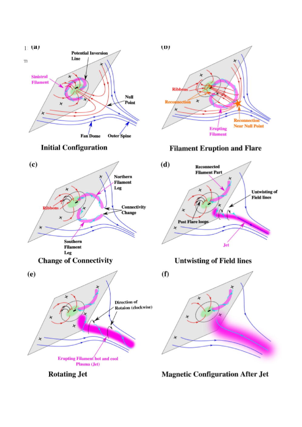
We analyzed a helical blowout jet which occurred on 2016 January 9. We discussed the interaction of the erupting mini-filament with the surrounding fan-spine structure, the origin of the rotation motion, and the associated CME in a context of the helical jet formation. We interpret the formation of the blowout jet as shown in the scheme in Figure 12. A mini-filament (pink color in Figure 12) is located inside the fan dome of a fan-spine configuration (c.f., Figures 1(a)– 1(d), 2, 3, and 12(a)). According to flux rope models (Martin, 1998, 2003; Filippov et al., 2015a, and references cited therein), the sinistral mini-filament is located inside a flux rope with the right-handed helix (cyan color in Figure 12(a)).
The blowout jet formation can be subdivided into three processes. First, the mini-filament is ejected upward by the instability and is accompanied by internal reconnection inside the fan dome. Secondly, the erupting filament interacts with the surrounding fan-spine structure (Figure 12(c)). At that time, the eruptive filament changes from the arch shape to the cusp shape and forms a radial jet (Figures 5(a)–(c)). Thirdly, the rotation motion is generated as the radial jet is developing. The untwisting motion of the twisted filament with the right–handed helix produced the clockwise rotation (Figures 7, and 12(e)). This untwisting motion straightens the field lines and at the end, only open magnetic field configuration is left (Figures 5(f), and 12(f)).
The present event is one of the clear examples which show overall steps of the formation and trigger processes of a blowout jet with high spatial and temporal resolutions. The event was initiated by a mini-filament eruption, triggered by flux convergence/cancellation in the quiet region, and followed by a helical jet formation. The presently studied jet is consistent with the new model for coronal jets that was first deduced by Adams et al. (2014) for a macrospicule in a coronal hole and was first deduced by Sterling et al. (2015) for all or nearly all blowout jets in coronal holes. Recently, Panesar et al. (2016) found that the same model fits blowout jets in non-coronal-hole regions such as quiet regions, which are similar to the jet occurring region in our study.
Shibata & Uchida (1986) discussed an unwinding motion of a twisted flux rope emerging into the open coronal fields as an origin of an H surge (see also (Kurokawa et al., 1987)). In their scenario, one leg of a flux rope gets combined with the ambient magnetic field to form a closed loop, while the other leg gets connected with the open field line to form a jet with a helical motion (see also Filippov et al., 2015b). This is consistent with our observation (Figure 12). It should be noted here that Shibata & Uchida (1986) and (Kurokawa et al., 1987) did not consider the fan-spine configuration as the ambient field. On the other hand, Filippov et al. (2015b) discussed the scenario in a fan-spine configuration, as in our observation and interpretation.
The rotation motions of blowout jets have been observed and interpreted as the untwisting of core flux ropes (e.g., Li et al., 2015; Moore et al., 2015). The transverse velocity of a helical blowout jet is reported like 95 by Hong et al. (2011), 25-70 by Liu et al. (2011), 60-220 by Moore et al. (2015), and 100-180 by Filippov et al. (2015b). These are comparable to our analysis (100 ) and macrospicule observations (Pike & Harrison, 1997; Parenti et al., 2002; Pike & Mason, 1998; Kamio et al., 2010; Scullion et al., 2009; Canfield et al., 1996; Jiang et al., 2007; Patsourakos et al., 2008; Shen et al., 2011; Lee et al., 2013).
More interestingly, we observed that the jet evolved like a standard jet in the initial phase from 13:43 UT to 13:51 UT. The twist manifests itself at 13:52 UT when the twisted southern leg starts unwinding. The 9-minutes time lag between the start times of the jet and the unwinding can be explained by the difference of the acceleration time scales. The jet is initially accelerated by magnetic reconnection in the corona and redirected by the ambient open magnetic fields. The time scale is determined by the local Alfven time scale, i.e. . On the other hand, the unwinding motion is controlled by the smaller magnetic tension force and decelerated by dense cool plasma inside the filament. This makes the acceleration time scale of the unwinding motion much larger than the one of the jet.
We observed a narrow CME associated with the jet in the LASCO C2 and C3 fields of view (Figure 11) that reached up to . The speed of the CME is observed to be around 630 which is faster than the initial jet speed (394 ). The transfer of magnetic helicity (or twist) from the low solar atmosphere to the corona pushes the jet material outward with increasing speed. The plasma acceleration mechanism (sweeping magnetic twist) in the jet is given by Shibata & Uchida (1986). They suggested that the untwisting motion produces the centrifugal force that accelerates the jet plasma. Later, Kurokawa et al. (1987) confirmed the scenario of a sweeping magnetic twist by analysing an erupting untwisting filament.
The generation of the helical motion of a jet is related to the generation of waves along magnetic field lines. This is an important issue for coronal heating and solar wind acceleration. The helical motion is commonly observed in macrospicules and also in spicules, and we revealed the generation process of the helical motion in the extreme case. The physical process of a helical blowout jet is related to the one of macrospicules (Kamio et al., 2010; Kayshap et al., 2013; Adams et al., 2014), which will be a key to reveal the helical motion generation of spicules and more fundamental physics of coronal streamers.
The exact process of reconnection between the erupting flux rope and the overlying fan–spine structure to trigger a blowout jets needs to be advanced. Also, the source of the rotation in blowout jets and the transport of helicity have to be discussed in detail. There is no simulation model available for this type of helical blowout jets with filament eruptions (and associated flux ropes) in fan–spine configurations. High–resolution observational study and numerical simulations are essential to understanding the overall process of formation and triggering of helical blowout jets in this kind of 3D magnetic configurations.
6 Conclusions
The main findings of this work are as follows.
-
1.
We calculated the fan-spine configuration above the monopole magnetic field area and found a mini-filament underlying the fan-spine configuration before a helical blowout jet eruption.
-
2.
The mini-filament erupted upward due to the magnetic flux-rope instability followed by internal reconnection, forming a two-ribbon structure at the footpoints of the post-flare loops. The filament interacted with the fan-spine magnetic structure, producing a helical blowout jet. This is consistent with an initiation of a blowout jet in models deduced by Adams et al. (2014) and Sterling et al. (2015).
-
3.
The jet shows a radial fast flow ( 400 ) and a horizontal rotation motion ( 60-120 ). The rotation motion of the jet is driven by the unwinding of the twist of the erupting mini-filament. The helicity of the sinistral filament matched the helicity of the rotating jet.
-
4.
The high speed of the associated narrow CME is the consequences of the magnetic reconnection and the helicity transfer from the lower to higher corona.
Acknowledgements
We thank the referee for his/her valuable comments and suggestions. We acknowledge the use of data taken by AIA and HMI on board SDO and LASCO on board SOHO. This work is supported by the BK21 plus program through the National Research Foundation (NRF) funded by the Ministry of Education of Korea. NCJ thanks, School of Space Research, Kyung Hee University for providing the postdoctoral grant. We are thankful to Drs. Sterling and Moore for their discussions and suggestions.
References
- Adams et al. (2014) Adams M., Sterling A. C., Moore R. L., Gary G. A., 2014, ApJ, 783, 11
- Alexander & Fletcher (1999) Alexander D., Fletcher L., 1999, Sol. Phys., 190, 167
- Archontis & Hood (2013) Archontis V., Hood A. W., 2013, ApJ, 769, L21
- Archontis et al. (2010) Archontis V., Tsinganos K., Gontikakis C., 2010, A&A, 512, L2
- Bennett & Erdélyi (2015) Bennett S. M., Erdélyi R., 2015, ApJ, 808, 135
- Brueckner et al. (1995) Brueckner G. E., et al., 1995, Sol. Phys., 162, 357
- Canfield et al. (1996) Canfield R. C., Reardon K. P., Leka K. D., Shibata K., Yokoyama T., Shimojo M., 1996, ApJ, 464, 1016
- Carmichael (1964) Carmichael H., 1964, NASA Special Publication, 50, 451
- Cheung et al. (2015) Cheung M. C. M., et al., 2015, ApJ, 801, 83
- Chifor et al. (2008a) Chifor C., Young P. R., Isobe H., Mason H. E., Tripathi D., Hara H., Yokoyama T., 2008a, A&A, 481, L57
- Chifor et al. (2008b) Chifor C., et al., 2008b, A&A, 491, 279
- Cirtain et al. (2007) Cirtain J. W., et al., 2007, Science, 318, 1580
- Filippov & Den (2001) Filippov B. P., Den O. G., 2001, J. Geophys. Res., 106, 25177
- Filippov et al. (2013) Filippov B., Koutchmy S., Tavabi E., 2013, Sol. Phys., 286, 143
- Filippov et al. (2015a) Filippov B., Martsenyuk O., Srivastava A. K., Uddin W., 2015a, Journal of Astrophysics and Astronomy, 36, 157
- Filippov et al. (2015b) Filippov B., Srivastava A. K., Dwivedi B. N., Masson S., Aulanier G., Joshi N. C., Uddin W., 2015b, MNRAS, 451, 1117
- Hirayama (1974) Hirayama T., 1974, Sol. Phys., 34, 323
- Hong et al. (2011) Hong J., Jiang Y., Zheng R., Yang J., Bi Y., Yang B., 2011, ApJ, 738, L20
- Hong et al. (2013) Hong J.-C., Jiang Y.-C., Yang J.-Y., Zheng R.-S., Bi Y., Li H.-D., Yang B., Yang D., 2013, Research in Astronomy and Astrophysics, 13, 253
- Jiang et al. (2007) Jiang Y. C., Chen H. D., Li K. J., Shen Y. D., Yang L. H., 2007, A&A, 469, 331
- Joshi et al. (2015) Joshi N. C., Liu C., Sun X., Wang H., Magara T., Moon Y.-J., 2015, ApJ, 812, 50
- Joshi et al. (2017) Joshi N. C., Chandra R., Guo Y., Magara T., Zhelyazkov I., Moon Y.-J., Uddin W., 2017, Ap&SS, 362, 10
- Kamio et al. (2010) Kamio S., Curdt W., Teriaca L., Inhester B., Solanki S. K., 2010, A&A, 510, L1
- Katsukawa et al. (2007) Katsukawa Y., et al., 2007, Science, 318, 1594
- Kayshap et al. (2013) Kayshap P., Srivastava A. K., Murawski K., Tripathi D., 2013, ApJ, 770, L3
- Kiss et al. (2017) Kiss T. S., Gyenge N., Erdélyi R., 2017, ApJ, 835, 47
- Kopp & Pneuman (1976) Kopp R. A., Pneuman G. W., 1976, Sol. Phys., 50, 85
- Kurokawa et al. (1987) Kurokawa H., Hanaoka Y., Shibata K., Uchida Y., 1987, Sol. Phys., 108, 251
- Lee et al. (2013) Lee K.-S., Innes D. E., Moon Y.-J., Shibata K., Lee J.-Y., Park Y.-D., 2013, ApJ, 766, 1
- Lee et al. (2015) Lee E. J., Archontis V., Hood A. W., 2015, ApJ, 798, L10
- Lemen et al. (2012) Lemen J. R., et al., 2012, Sol. Phys., 275, 17
- Li et al. (2015) Li X., Yang S., Chen H., Li T., Zhang J., 2015, ApJ, 814, L13
- Liu et al. (2011) Liu W., Berger T. E., Title A. M., Tarbell T. D., Low B. C., 2011, ApJ, 728, 103
- Martin (1998) Martin S. F., 1998, in Webb D. F., Schmieder B., Rust D. M., eds, Astronomical Society of the Pacific Conference Series Vol. 150, IAU Colloq. 167: New Perspectives on Solar Prominences. p. 419
- Martin (2003) Martin S. F., 2003, Advances in Space Research, 32, 1883
- Moore et al. (2010) Moore R. L., Cirtain J. W., Sterling A. C., Falconer D. A., 2010, ApJ, 720, 757
- Moore et al. (2015) Moore R. L., Sterling A. C., Falconer D. A., 2015, ApJ, 806, 11
- Moreno-Insertis & Galsgaard (2013) Moreno-Insertis F., Galsgaard K., 2013, ApJ, 771, 20
- Moreno-Insertis et al. (2008) Moreno-Insertis F., Galsgaard K., Ugarte-Urra I., 2008, ApJ, 673, L211
- Nishizuka et al. (2008) Nishizuka N., Shimizu M., Nakamura T., Otsuji K., Okamoto T. J., Katsukawa Y., Shibata K., 2008, ApJ, 683, L83
- Nishizuka et al. (2011) Nishizuka N., Nakamura T., Kawate T., Singh K. A. P., Shibata K., 2011, ApJ, 731, 43
- Panesar et al. (2016) Panesar N. K., Sterling A. C., Moore R. L., Chakrapani P., 2016, ApJ, 832, L7
- Parenti et al. (2002) Parenti S., Bromage B. J. I., Bromage G. E., 2002, A&A, 384, 303
- Pariat et al. (2015) Pariat E., Dalmasse K., DeVore C. R., Antiochos S. K., Karpen J. T., 2015, A&A, 573, A130
- Patsourakos et al. (2008) Patsourakos S., Pariat E., Vourlidas A., Antiochos S. K., Wuelser J. P., 2008, ApJ, 680, L73
- Pesnell et al. (2012) Pesnell W. D., Thompson B. J., Chamberlin P. C., 2012, Sol. Phys., 275, 3
- Pevtsov et al. (2003) Pevtsov A. A., Balasubramaniam K. S., Rogers J. W., 2003, ApJ, 595, 500
- Pike & Harrison (1997) Pike C. D., Harrison R. A., 1997, Sol. Phys., 175, 457
- Pike & Mason (1998) Pike C. D., Mason H. E., 1998, Sol. Phys., 182, 333
- Savcheva et al. (2007) Savcheva A., et al., 2007, PASJ, 59, S771
- Schmieder et al. (1995) Schmieder B., Shibata K., van Driel-Gesztelyi L., Freeland S., 1995, Sol. Phys., 156, 245
- Schmieder et al. (2013) Schmieder B., et al., 2013, A&A, 559, A1
- Schou et al. (2012) Schou J., et al., 2012, Sol. Phys., 275, 229
- Scullion et al. (2009) Scullion E., Popescu M. D., Banerjee D., Doyle J. G., Erdélyi R., 2009, ApJ, 704, 1385
- Shen et al. (2011) Shen Y., Liu Y., Su J., Ibrahim A., 2011, ApJ, 735, L43
- Shen et al. (2012) Shen Y., Liu Y., Su J., Deng Y., 2012, ApJ, 745, 164
- Shibata & Suematsu (1982) Shibata K., Suematsu Y., 1982, Sol. Phys., 78, 333
- Shibata & Uchida (1986) Shibata K., Uchida Y., 1986, Sol. Phys., 103, 299
- Shibata et al. (1992) Shibata K., et al., 1992, PASJ, 44, L173
- Shibata et al. (1994) Shibata K., Nitta N., Strong K. T., Matsumoto R., Yokoyama T., Hirayama T., Hudson H., Ogawara Y., 1994, ApJ, 431, L51
- Shibata et al. (2007) Shibata K., et al., 2007, Science, 318, 1591
- Shimojo et al. (1998) Shimojo M., Shibata K., Harvey K. L., 1998, Sol. Phys., 178, 379
- Shimojo et al. (2001) Shimojo M., Shibata K., Yokoyama T., Hori K., 2001, ApJ, 550, 1051
- Singh et al. (2011) Singh K. A. P., Shibata K., Nishizuka N., Isobe H., 2011, Physics of Plasmas, 18, 111210
- Singh et al. (2012) Singh K. A. P., Isobe H., Nishizuka N., Nishida K., Shibata K., 2012, ApJ, 759, 33
- Sterling (2000) Sterling A. C., 2000, Sol. Phys., 196, 79
- Sterling et al. (2010) Sterling A. C., Harra L. K., Moore R. L., 2010, ApJ, 722, 1644
- Sterling et al. (2015) Sterling A. C., Moore R. L., Falconer D. A., Adams M., 2015, Nature, 523, 437
- Sturrock (1966) Sturrock P. A., 1966, Nature, 211, 695
- Uddin et al. (2012) Uddin W., Schmieder B., Chandra R., Srivastava A. K., Kumar P., Bisht S., 2012, ApJ, 752, 70
- Wang & Sheeley (2002) Wang Y.-M., Sheeley Jr. N. R., 2002, ApJ, 575, 542
- Yamauchi et al. (2005) Yamauchi Y., Wang H., Jiang Y., Schwadron N., Moore R. L., 2005, ApJ, 629, 572
- Yokoyama & Shibata (1995) Yokoyama T., Shibata K., 1995, Nature, 375, 42
- Yokoyama & Shibata (1996) Yokoyama T., Shibata K., 1996, PASJ, 48, 353
- Young & Muglach (2014) Young P. R., Muglach K., 2014, Sol. Phys., 289, 3313