🖂 andrey.mokhov@ncl.ac.uk
Formal Verification of Spacecraft Control Programs Using a Metalanguage for State Transformers
Abstract
Verification of functional correctness of control programs is an essential task for the development of space electronics; it is difficult and time-consuming and typically outweighs design and programming tasks in terms of development hours. We present a verification approach designed to help spacecraft engineers reduce the effort required for formal verification of low-level control programs executed on custom hardware. The approach uses a metalanguage to describe the semantics of a program as a state transformer, which can be compiled to multiple targets for testing, formal verification, and code generation. The metalanguage itself is embedded in a strongly-typed host language (Haskell), providing a way to prove program properties at the type level, which can shorten the feedback loop and further increase the productivity of engineers.
The verification approach is demonstrated on an industrial case study. We present REDFIN, a processing core used in space missions, and its formal semantics expressed using the proposed metalanguage, followed by a detailed example of verification of a simple control program.
Keywords:
formal verification, instruction set architecture, functional programming, domain-specific languages.1 Introduction
Software bugs play a major role in the history of spacecraft accidents [14]. There are recorded cases of mission-ending bugs that would have been difficult to prevent (e.g. caused by concurrency or updates) but also plain integer overflows [3] and incorrect unit conversion [2], which should have been eradicated long ago.
Alas, there is no silver bullet. Testing is supported by mature methodologies and frameworks, but does not provide the full correctness guarantee. General-purpose strongly-typed languages can be used to eliminate important classes of bugs, but are less familiar to software engineers and are often not suitable for highly resource-constrained microarchitectures used in space electronics. Formal modelling methods provide a systematic approach for developing complex systems in a correct-by-construction manner, but they are still at the bleeding-edge of computing science and can be difficult to apply to real-life systems. This paper combines known formal verification and programming languages techniques and presents a formal verification approach for simple control tasks, such as satellite power management, which are executed on a real processing core used in space missions. We believe the presented ideas are transferable to other domains with similar safety and resource requirements, e.g. biomedical applications.
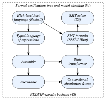
Fig. 1 shows an overview of the presented approach. The bottom part corresponds to conventional code generation and simulation, where REDFIN111REDFIN stands for ‘REDuced instruction set for Fixed-point & INteger arithmetic’. This instruction set and the corresponding processing core were developed by RUAG Space Austria GmbH for space missions. See §2 for more details. assembly language is executed by simulating the effect of each instruction on the state of the processor and memory. The corresponding state transformer is typically implicit and intertwined with the rest of the simulation infrastructure. The main idea of our approach is to represent the state transformer explicitly so that it can be symbolically manipulated and used not only for simulation but also for formal verification by compiling it into an SMT formula. We can then use an SMT solver, e.g. Z3 [6], to verify that the state transformer of a given program satisfies certain properties, for example, that integer overflow cannot occur regardless of input parameters and that the program always terminates within given time.
By embedding the state transformer metalanguage in Haskell we can readily implement compilers from higher-level typed languages to untyped assembly, eradicating incorrect number and unit conversion bugs. As shown at the top of Fig. 1, engineers can write high-level control programs for the REDFIN architecture directly in a small subset of Haskell. These high-level programs can be used for type-safe code generation and as executable specifications of intended functionality for the purposes of program synthesis and equivalence checking.
2 The REDFIN overview
For many spacecraft subsystems integrated circuits are required to perform control tasks or simple data processing. Typically, these integrated circuits are realised with FPGAs (Field Programmable Gate Arrays) due to their flexibility and lower costs compared to ASIC (Application-Specific Integrated Circuit) development & fabrication. Since FPGAs can be used to implement arbitrary circuit functions including processor cores, it is possible to perform tasks both in hardware and in software. However, modern space-qualified FPGAs, which can withstand radiation in Earth orbit or deep space, have a limited amount of programmable resources. Therefore, it is often not feasible to implement a fully-fledged processor system in such an FPGA next to the mission-specific circuitry.
The REDFIN instruction set was developed to address this issue and, more specifically, to meet the following goals: (i) simple instruction set to achieve a small hardware footprint, (ii) reduced complexity to support formal verification of programs, and (iii) deterministic behaviour for real-time applications.
2.1 REDFIN instruction set and microarchitecture
The instruction set architecture offers a configurable bit width for the data path, ranging from 8 to 64 bits. Instruction words have a fixed width of 16 bits. The instruction set is based on a register-memory architecture, i.e. instructions can fetch their operands from registers as well as directly from the memory. This architecture favours a small register set, which minimises the hardware footprint of the processing core. Furthermore, the number of instructions in a program is typically smaller in comparison to traditional load/store architectures where all operands have to be transferred to registers before any operations can be performed. There are 47 instructions of the following types:
-
•
Load/store instructions for moving data words between general- and special-purpose registers and the memory, as well as load of immediate values.
-
•
Arithmetic operations for integer and fixed-point numbers. In the latter case the number of fractional bits can be adjusted by a processor register.
-
•
Bitwise logical and shift operations.
-
•
Control flow instructions and associated comparison operations.
-
•
Bus access instructions for read & write operations on an AMBA AHB bus.
The REDFIN processing core fetches instruction and data words from a small and fast on-chip SRAM. This only allows for execution of simple programs, however, it also eliminates the need to implement caches and thus removes a source of non-determinism of conventional processors. Since computing performance is not one of the main goals, the processor core is non-pipelined and therefore does not need to resolve data or control hazards or perform any form of speculative execution. These properties greatly simplify worst case execution time analysis.
2.2 Requirements for formal verification
Verification of functional correctness of REDFIN programs, as defined by a requirement specification, clearly is an essential task for the development of space electronics. There are also important non-functional requirements, such as worst case execution time and energy consumption, which rely on the implementation guarantees provided by the processing core. In order to reduce verification complexity, the REDFIN core only allows to execute a single subroutine whose execution is triggered by a higher-level controller in the system. The implementation also guarantees that concurrent bus accesses to the processor registers or memory do not affect the subroutine execution time. Furthermore, the processor does not implement interrupt handling. All these measures are taken in order to provide real-time subroutine execution guarantees and make the verification of non-functional properties feasible within the presented verification framework.
Despite these restrictions the REDFIN core has already proven its effectiveness for simple control tasks and arithmetic computations as part of an antenna pointing unit for satellites. Nevertheless, verification can be difficult and time-consuming, even for small and simple programs. Verification activities, following engineering standards for space electronics, typically outweigh programming and design tasks by a factor of two in terms of development hours. Usually verification is performed via program execution on an instruction set simulator or a hardware model of the processor. Manually deriving test cases from the specification is cumbersome and error-prone and simulation times can become prohibitively long with a large number of tests that are often needed to reach the desired functional and code coverage. Formal verification methods can prove that a program satisfies certain properties for all possible test cases and are therefore immensely valuable for completing the verification with superior efficiency and quality.
3 State transformer
In this section we formally define the REDFIN microarchitecture and express the semantics of the instruction set as an explicit and symbolic state transformer.
3.1 The REDFIN microarchitecture state
The main idea of the presented approach is to use an explicit state-transformer semantics of the REDFIN microarchitecture. The state space of the entire processing core is a Cartesian product of state spaces of every component:
where is the set of register bank configurations; is the memory state space; is the set of instruction addresses (the instruction counter stores the address of the current instruction); is the set of instruction codes (the instruction register stores the code of the current instruction); is the set of programs; is the set of the flag register configurations; and is the set of clock values.
Fig. 3.1 shows the translation of the above into Haskell types. Note that the types are not parameterised: recall that REDFIN is parameterised, e.g. the data width can be chosen depending on mission requirements, whereas we use fixed 64-bit data path for the sake of simplicity. The chosen names are self-explanatory, for example, the data type
State} directly corresponds to the set of states~$S$.
We defined \hs
SymbolicValue and
SymbolicArray} type constructors on top of
Levent Erkok’s symbolic verification library SBV~\cite
SBV, which we use as the SMT translation and verification frontend. In principle, any other SMT frontend can be used, but to the best of our knowledge, SBV is the most mature SMT library available for Haskell. We briefly overview all
State} components below.
\begin
figure[t]
Basic types for encoding REDFIN microarchitecture in Haskell.
3.1.1 Data values, registers and memory
64-bit data values (
Int64}) are stored in registers and memory. There are~4
registers (addressed by \hs
Word2) and 256 memory locations (addressed by
Word8}). Their content is represented by symbolic arrays that can be
accessed via SBV’s functions \hs
readArray and
writeArray}.
\vspace
-4.5mm
3.1.2 Instructions and programs
REDFIN instructions are represented by 16-bit
InstructionCode}, whose 6
leading bits contain the instruction opcode, and the remaining 10 bits are
allocated for various instruction arguments. The \hs
Program is a symbolic array mapping 8-bit instruction addresses to instruction codes.
3.1.3 Status flags and clock
The microarchitecture stores execution status flags to support conditional branching, track integer overflow, and terminate the program, as captured by the data type
Flag} (we omit a few other flags for brevity). The flag register is a
symbolic map from flags to Boolean values. The \hs
Clock is a 64-bit counter incremented on each clock cycle. Status flags and the clock are used for diagnostic, formal verification and worst-case execution time analysis.
3.2 Instruction and program semantics
We can now define the formal semantics of REDFIN instructions and programs in terms
of a state transformer , i.e. a function that maps
states to states. We distinguish between instructions and programs by using
Haskell’s list notation, for example, , whereas nop}\hs] ∈Pp ∈P.
The semantics of the single-instruction program
]} \in P$
    is a composition of three state transformers: (i) fetching the instruction from
the program memory (denoted by $T_\textitfetchT_incT_i}}$), that is:
\vspace-1.5mm
The semantics of the composite program
p} \in P$,
    where the operator~\hs
: prepends an instruction ∈PT_i}\subhs:p}} = T_p}} \circ T_[}\subhsi]}}$.
\vspace-1mm
We represent state transformers in Haskell using the state monad, a
classic approach to emulating mutable state in a purely functional programming
language [22]. We call our state monad Redfin} and define it\footnoteA generic version of this monad is available in standard module
. as follows:
Every computation with the return type Redfin} \hsa yields a value of type
a}
and possibly alters the \hs
State of the REDFIN microarchitecture. As an example, below we express the state transformer using the
Redfin} monad.
\vspace
-0.5mm
In words, the state transformer looks up the value of the
instructionCounter}
in the \hs
current state and replaces it in the
next} state with the
incremented~value. The type \hs
Redfin () indicates that the computation does not produce any value as part of the state transformation. Such computations directly correspond to REDFIN programs and can be composed using the operator
>>}.
For example, \hs
fetchInstruction
>>}~\hsincrementInstructionCounter is
the state transformer assuming that
fetchInstruction} corresponds to $T_\textitfetch
Here
readInstructionRegister} extracts the instruction code from the current
state \emph
without modifying it. This function is used in
executeInstruction},
which defines the semantics of the REDFIN execution cycle. We omit the definition of
\hs
decodeAndExecute for brevity: it is a case analysis of 47 opcodes that returns the matching instruction. We introduce several interesting instructions below.
3.2.1 Halting the processor
If the halt} instruction is encountered, the processor sets the flag~\hsHalt,
thereby stopping the execution of the current subroutine until a new one is
started by a higher-level system controller that resets
Halt}. The auxiliary
function \hs
writeFlag is used to do the actual flag modification.
3.2.2 Arithmetics
As a more involved example, consider the semantics of the instruction
abs}.
It reads a register and writes back the absolute value of its
contents\footnote
We use
Prelude.abs} to distinguish between the instruction
and the function from the standard library \hs
Prelude;
fmap} applies
\hs
Prelude.abs to the result of
readRegister}.}.
The semantics accounts for the potential integer overflow that leads to the
\emph
negative resulting value when the input is (REDFIN uses the two’s complement signed number representation). The overflow is flagged by setting
Overflow}.
\vspace
-1.5mm
Here, SBV’s symbolic if-then-else operation ite} is used to \emphmerge
two possible next states, one of which has the
Overflow} flag set. We use
auxiliary functions \hs
readRegister,
writeRegister}, \hsreadState and
writeState} --- simple state transformers defined similarly to
\hs
readInstructionRegister and
writeFlag}.
\vspace
-4.5mm
3.2.3 Conditional branching
As an example of a control flow instruction, consider the conditional branching
instruction jmpi_ct}, which tests the~\hsCondition flag, and adds the
provided offset to the instruction counter if the flag is set.
After working through the above examples, it is worth noting that we use our Haskell encoding of the state transformer as a metalanguage. We are operating the REDFIN core as a puppet master, using external meta-notions of addition, comparison and let-binding. From the processor’s point of view, we have infinite memory and act instantly, which gives us unlimited modelling power. For example, we can run a simulation of the processor environment in an external tool and feed its result to
writeRegister} as if it was
obtained in a single clock cycle.
\vspace
-1.5mm
3.3 Symbolic simulation
Having defined the semantics of REDFIN instructions and programs, we can implement symbolic simulation of the processor:
The function takes a number of simulation steps and an initial symbolic
state of the processor as input, and executes instructions using the
previously defined executeInstruction} function. In each \hsstate we need
to merge two possible futures depending on the value of the
Halt} flag:
(i) continue the simulation starting from the \hs
nextState if the flag is not set, and (ii) remain in the current
state} if the flag is set, since in
this case the processor must remain idle.
%TODO: What about program synthesis?
Symbolic simulation is very powerful. It allows us to formally verify properties
of REDFIN programs by fixing some parts of the state to constant values (for
example, the program code), and then checking assertions on the resulting values of
the symbolic part of the state. This will be discussed in the next
section~\S\ref
sec-verification.
4 Formal verification
This section presents the formal verification framework developed on top of the REDFIN semantic core (§3) demonstrating the following steps of the workflow:
-
•
Develop programs either in low-level REDFIN assembly, or in a high-level and statically type-checked expression language embedded in Haskell.
-
•
Initialise, execute and test REDFIN programs on concrete input values.
-
•
Formulate and refine functional correctness and worst case execution time properties in the SBV property specification language.
-
•
Verify the properties with an SMT solver.
-
•
Receive the verification results (e.g. counterexamples) for analysis.
As our running example, consider the following simple spacecraft control task. This task looks too simple, but in fact it has a few critical pitfalls that, if left unattended, may lead to the failure of the whole space mission. Examples of subtle bugs in seemingly simple programs leading to a catastrophe include 64-bit to 16-bit number conversion overflow causing the destruction of Ariane 5 rocket [3] and the loss of NASA’s Mars climate orbiter due to incorrect units of measurement conversion [2]. Let us develop and verify a REDFIN program for this task.
4.0.1 Writing the program
We can write programs either directly in the untyped REDFIN assembly, or in a typed higher-level expression language. Both have their advantages: the former allows engineers to hand-craft highly optimised programs under tight resource constraints, and the latter brings type-safety and faster prototyping. Our first prototype therefore uses the high-level approach. Using Haskell’s polymorphism, we can define an expression that can be used both as a Haskell function and a high-level REDFIN expression:
We implement the energy estimation program by embedding the
energyEstimate}
expression into a REDFIN~\hs
Script. Due to the lack of space we omit the implementation of
Script}, but one can think of it as a restricted version
of the \hs
Redfin state transformer, which we use to write programs that can manipulate the processor state only by executing instructions, e.g. the only way to set the
Overflow} flag is to execute an arithmetic instruction
that actually has an overflow.
\vspace
-1mm
Here the type
IntegerVariable} is used to statically distinguish between integer
and fixed-point numbers, \hs
Temporary to mark temporary words, so they cannot be mixed with inputs and outputs, and
Stack} to denote the location of the
stack pointer. The~\hs
let block declares six adjacent memory addresses: four input values , a temporary word and a stack pointer. The
compile} function call at line~9 performs the embedding of the high-level
\hs
energyEstimate expression into the assembly language by translating it to a sequence of REDFIN instructions. The first argument of the
compile} function
holds the register~\hs
r0 which contains the estimated energy value after the program execution.
4.0.2 Simulating the program
We run symbolic simulation for 100 steps, initialising the program and data memory of the processor using the helper function
boot}.
\begin
mintedhaskell main :: IO () main = do let dataMemory = [10, 5, 3, 5, 0, 100] finalState = simulate 100 (boot energyEstimateHighLevel dataMemory) printMemoryDump 0 5 (memory finalState) putStrLn . Note that the stack pointer (cell 5) holds 100 as in the initial state, which means the stack is empty.
Simulating programs with concrete input values is useful for diagnostic and test. However, to formally verify their functional correctness, we need to inspect every valid combination of input values, which can be done by an SMT solver. This allows us to discover a trap hidden in our energy estimation program.
4.0.3 Verifying the program
The project lead engineer defined a set of functional requirements for the energy monitoring subsystem. The software engineering team received the specification, implemented the energy monitoring subroutines, and started the verification. One of the requirements is as follows. To check that the program complies with the requirement, we translate the symbolic state transformer
energyEstimateHighLevel} into an SMT formula,
and formulate the following theorem. Lines 13-14 extract the computed result and
the value of the flag \hs
Halt from the
finalState}. Lines 15-16 require that
the processor has halted, the result is equal to that computed by the high-level
Haskell expression \hs
energyEstimate and is non-negative.
The resulting SMT formula has 122 clauses and can be checked by Z3 in 3.0s222All reported results are obtained on a laptop with 2.90GHz Intel Core i5-4300U processor, 8GB RAM (3MB cache), and the SMT solver Z3 version 4.5.1 (64-bit).:
The solver has found a counterexample demonstrating that the program does not satisfy the above requirement. Indeed, the expression evaluates to a negative value on the provided inputs due to an integer overflow. The following refined requirement is then provided by the project lead engineer: The software engineering team modifies the time333We are not absolutely precise here. We do not distinguish between regular and leap years, and use a conservative upper bound of 366 days per year. and power constraints:
We rerun Z3 (now on 134 SMT clauses) and get the desired outcome in 4.8s:
The refinement of the requirement has rendered the integer overflow impossible,
in particular, we can now be sure that abs} cannot be called with~$-2^63
4.0.4 Checking program equivalence
The statically typed high-level expression language is very convenient for writing REDFIN programs, however, an experienced engineer can often find a way to improve the resulting code. In some particularly resource-constrained situations, a fully hand-crafted assembly code may be required. As an example, a direct unoptimised translation of the
energyEstimate} expression into assembly uses
79 instructions, most of them for \hs
Stack manipulation. On the other hand, it is not difficult to write a low-level assembly program that computes the result using only 9 instructions as we demonstrate below. To facilitate the development of verified hand-crafted code, we use an SMT solver to check the equivalence of REDFIN programs by verifying that they produce the same output on all valid inputs. This allows an engineer to manually optimise a given high-level prototype and have a guarantee that no bugs were introduced in the process. An optimised low-level energy estimation program has only 9 instructions:
Below we define the equivalence} check of this low-level program with the
high-level program \hsenergyEstimateHighLevel introduced earlier.
We run Z3 (now on 52 SMT clauses) and get the affirmative result in 11.5s:
4.0.5 Program timing analysis
The REDFIN semantic core implements the system clock tracking with the
delay}
function:
\vspace
-1mm
Every execution step – a call of the
executeInstruction} function~-- advances
the clock by the number of cycles required to do the associated computation as well
as memory and register accesses. The tracking is precisely matched to the hardware
implementation and enables the engineers to
perform~\emph
best/worst case execution timing analysis exploiting the optimisation facilities provided by SBV and Z3. As an example, let us determine the minimum and maximum number of clock cycles required for executing
energyEstimateLowLevel}. For the sake of making this example more
interesting, we modified the semantics of the instruction~\hs
abs and added 1 extra clock cycle in case of a negative argument by conditionally performing
delay 1} in the state transformer \hsabs.
The total delay of the program depends only on the sign of , thus the best and worst cases differ only by one clock cycle. The worst case is achieved when the difference is negative (), as shown below. Z3 finishes in 0.5s. ⬇ Objective "Best case": Optimal model: t1 = 549755813888 t2 = 17179869184 p1 = 0 p2 = 0 Best case = 12 ⬇ Objective "Worst case": Optimal model: t1 = 65535 t2 = 65537 p1 = 0 p2 = 0 Worst case = 13
5 Discussion
The presented approach has been implemented and is planned to be released at the conference (this paper is currently under review). In this section we discuss our main design choices and achieved results, comparing them with the project’s initial goals: (i) providing a unified specification, testing, and formal verification framework that is (ii) understandable and convenient to use by the REDFIN engineering team, and (iii) allows the team to co-develop REDFIN software and hardware, by extending and modifying the default instruction semantics.
5.1 From hardware to untyped assembly to typed software
The proposed approach covers two levels of organisation of computer systems: the
hardware microarchitecture (the state monad Redfin},~\S\refsec-transformer),
and the instruction set architecture (the assembly monad
Script},~\S\refsec-verification). These two levels are very different: the
former allows hardware engineers to precisely capture the program semantics (and
has proven useful in exposing underspecified behaviours), whereas the latter does
not have a direct access to the microarchitectural level and is used to
symbolically execute the semantics, allowing software engineers to
observe the results and reason about program correctness.
By using Haskell as a metalanguage, we provided a purely syntactic implementation
of a higher-level abstraction on top of the REDFIN assembly — a statically-typed
language for arithmetic expressions. This demonstrates that the user
of the verification framework has enough power to implement their own domain-specific
extensions of the REDFIN assembly.
Although our current implementation is written in Haskell, the presented ideas
can be implemented in many other languages. We chose Haskell for its built-in
support for polymorphic expressions, powerful
do}-notation, and availability
of a mature symbolic manipulation library (SBV). We also have a prototype
implementation in Idris, a much younger language that features dependent
types and hence allows us to verify more sophisticated properties at the type
level~\cite
JFP:9060502, however at the time of writing there is no equivalent of the SBV library in Idris, which is a significant practical disadvantage. Dependent Haskell [24], once implemented, will provide a convenient alternative.
5.2 Uniform development, testing and verification environment
The
Script} monad was engineered to provide familiar assembly mnemonics and
directives (e.g. data and instruction labels), which allows engineers to start
using the framework for developing REDFIN programs even without prior experience
of Haskell development, hopefully increasing the uptake of the framework.
Thanks to symbolic simulation, we can uniformly handle both concrete and
symbolic values, thus testing becomes just a special case of formal verification,
allowing the engineers to reuse a common code base and infrastructure.
Testing yields trivial SMT problems that can be solved in sub-second time for
all programs of realistic sizes (typical REDFIN programs have hundreds of
instructions). Formal verification is more expensive: in our experiments, we
could handle programs comprising hundreds of instructions in 10-15 minutes, but
one can easily construct small programs that will grind any SMT solver to a halt:
for example, analysis of a single multiplication instruction \hs
mul can take half an hour if it is required to factor 64-bit numbers (try factoring
4611686585363088391} with an SMT solver). In such cases, conservatively proving
some of the correctness properties at the type level can significantly increase
the productivity.
Although proving properties about the hardware implementation is left for future
work, the developed infrastructure provides a way to generate testsuites for the
processing core from the formal semantics of REDFIN instructions. Furthermore,
one can use the semantics to generate parts of the hardware
implementation~\cite
reid2016cav or synthesise efficient instruction subsets [17].
6 Related Work
There is a vast body of literature available on the topic of formal verification, including verification of hardware processing cores and low-level software programs. Our work builds in a substantial way on a few known ideas that we will review in this section. We thank the formal verification and programming languages communities and hope that the formal semantics of the REDFIN processing core will provide a new interesting benchmark for future studies. We model the REDFIN microarchitecture using a monadic state transformer metalanguage. There are several examples of prior work exploiting this idea. Fox and Myreen [9] formalise the Arm v7 instruction set architecture in HOL4 and give a careful account to bit-accurate proofs of the instruction decoder correctness. Later, Kennedy et al. [12] formalised a subset of the x86 architecture in Coq, using monads for instruction execution semantics and monadic
do}-notation for assembly language embedding.
Both these models are formalised in proof assistants, thus are powered by full
dependent types, which allow the usage of mechanised program correctness proofs.
Degenbaev~\cite
degenbaev2012formal formally specifies the complete x86 instruction set – a truly monumental effort! – using a custom domain-specific language that can be translated to a formal proof system. Arm’s Architecture Specification Language has been developed for the same purpose to formalise the Arm v8 instruction set [20]. Our specification approach is similar to these two works, but we operate on a much smaller scale of the REDFIN core. Our monadic metalanguage is embedded in Haskell and does not have a rigorous formalisation, i.e. we cannot prove correctness of the REDFIN semantics itself (this is a common concern, e.g. see [19]). Moreover, our verification workflow mainly relies on automated theorem proving, rather than on interactive one. This is motivated by the cost of precise proof assistant formalisations in terms of human resources: automated techniques are more CPU-intensive, but cause less “human-scaling issues” (Reid at al. [20]). Our goal was to create a framework that could be seamlessly integrated into an existing spacecraft engineering workflow, therefore it needed to have as much proof automation as possible. The automation is achieved by means of symbolic program execution. Currie at al. [5] applied symbolic execution with uninterpreted functions to prove equivalence of low-level assembly programs. The framework we present allows not only proving the equivalence of low-level programs, but also their compliance with higher-level specifications written in a subset of Haskell. A lot of research work has been done on the design of typed assembly languages, e.g. see [10][18]. The low-level REDFIN assembly is untyped, but the syntactic language of arithmetic expressions that we implemented on top of it does have a simple type system. In principle, the REDFIN assembly itself may benefit from a richer type system, especially one enforcing correct operation with relevant mission-specific units of measurement [13]. Finally, we would like to acknowledge several related projects, blogposts and talks that provided an initial inspiration for this work: the ‘Monads to Machine Code’ compiler by Diehl [8], RISC-V semantics in Haskell by MIT [16], Wall’s assembly monad [23], and SMT-based program analysis by Jelvis [11].
7 Conclusions and opportunities for future research
This paper presents a formal verification approach developed to tackle a real engineering problem by combining known techniques from the formal verification and programming languages research communities. We demonstrated that these techniques can be applied to create a formal model of the spacecraft processing core REDFIN that is used to execute small control programs, and showed how to formally verify such programs. By releasing the state transformer semantics to public, we hope to provide other researchers with a realistic benchmark for their formal verification tools. We also invite them to contribute to the REDFIN toolchain itself. Below we list opportunities for future research.
7.1 Dependently-typed high-level DSL for REDFIN programs
On top of low-level REDFIN assembly we implemented a high-level arithmetic expression language with a simple type system to distinguish between variables using different number representation and measurement units. This very simple type system already helps to eliminate an important class of bugs with the help of Haskell’s type checker. However, a dependently-typed host language, such as Agda, Coq, Dependent Haskell, or Idris, could provide us much more power. One example is compile-time elimination of out-of-memory access that can occur when branching to a non-existent program location or overflowing the stack.
7.2 System-level verification via strongly typed protocols
The REDFIN instruction set architecture has a number of bus-communication instructions to access the system bus. An interesting research problem is implementing a model of a complete space system in an advanced typed programming language by modelling each component separately and later integrating them using shared types specifying the communication protocol. We can then derive bus-communication code from the protocol specification, while sharing the same types on both sides will allow ensuring the correctness of communication. Similar work has been done in the context of web systems [15].
7.3 Hardware synthesis
The state transformer metalanguage presented in the paper makes the system state explicit and employs Haskell’s advanced abstractions to make the state manipulation safe and structured. To convey the model’s verification power down to the bare metal, we can implement a verified translation from the state-transformer metalanguage to a hardware description language to petrify the semantics and turn it into silicon.
Acknowledgements
We would like to thank Neil Mitchell, Charles Morisset, Artem Pelenitsyn and Danil Sokolov for their helpful feedback on an earlier version of this paper.
References
- [1] SBV: SMT Based Verification in Haskell, http://leventerkok.github.io/sbv/
- [2] Mars Climate Orbiter Mishap Investigation Board Phase I Report. Tech. rep., NASA (Nov 1999)
- [3] Ben-Ari, M.: The Bug That Destroyed a Rocket. SIGCSE Bull. 33(2), 58–59 (June 2001)
- [4] Brady, E.: Idris, a general-purpose dependently typed programming language: Design and implementation. Journal of Functional Programming 23, 552–593 (9 2013)
- [5] Currie, D., Feng, X., Fujita, M., Hu, A.J., Kwan, M., Rajan, S.: Embedded Software Verification Using Symbolic Execution and Uninterpreted Functions. International Journal of Parallel Programming 34(1), 61–91 (2006)
- [6] De Moura, L., Bjørner, N.: Z3: An efficient SMT solver. Tools and Algorithms for the Construction and Analysis of Systems pp. 337–340 (2008)
- [7] Degenbaev, U.: Formal specification of the x86 instruction set architecture. Ph.D. thesis, Saarland University (2012)
- [8] Diehl, S.: Monads to Machine Code. http://www.stephendiehl.com/posts/monads_machine_code.html (2017)
- [9] Fox, A., Myreen, M.O.: A trustworthy monadic formalization of the ARMv7 instruction set architecture. In: International Conference on Interactive Theorem Proving. pp. 243–258. Springer (2010)
- [10] Haas, A., Rossberg, A., Schuff, D.L., Titzer, B.L., Holman, M., Gohman, D., Wagner, L., Zakai, A., Bastien, J.: Bringing the Web Up to Speed with WebAssembly. SIGPLAN Not. 52(6), 185–200 (2017)
- [11] Jelvis, T.: Analyzing Programs with Z3 (video recording of Compose Conference talk). http://jelv.is/talks/compose-2016 (2016)
- [12] Kennedy, A., Benton, N., Jensen, J.B., Dagand, P.E.: Coq: the world’s best macro assembler? In: Proceedings of the 15th Symposium on Principles and Practice of Declarative Programming. pp. 13–24. ACM (2013)
- [13] Kennedy, A.J.: Relational Parametricity and Units of Measure. In: Proceedings of the 24th ACM SIGPLAN-SIGACT Symposium on Principles of Programming Languages. pp. 442–455. POPL’97, ACM (1997)
- [14] Leveson, N.G.: Role of Software in Spacecraft Accidents. Journal of Spacecraft and Rockets 41(4), 564–575 (2004)
- [15] Mestanogullari, A., Hahn, S., Arni, J.K., Löh, A.: Type-level Web APIs with Servant: An Exercise in Domain-specific Generic Programming. In: Proceedings of the 11th ACM SIGPLAN Workshop on Generic Programming. pp. 1–12. WGP 2015, ACM (2015)
- [16] MIT CSAIL: A formal specification of the RISC-V ISA written in Haskell. https://github.com/mit-plv/riscv-semantics (2017)
- [17] Mokhov, A., Iliasov, A., Sokolov, D., Rykunov, M., Yakovlev, A., Romanovsky, A.: Synthesis of processor instruction sets from high-level ISA specifications. IEEE Transactions on Computers 63(6), 1552–1566 (2014)
- [18] Morrisett, G., Walker, D., Crary, K., Glew, N.: From System F to Typed Assembly Language. ACM Trans. Program. Lang. Syst. 21(3), 527–568 (1999)
- [19] Reid, A.: Who Guards the Guards? Formal Validation of the Arm V8-m Architecture Specification. Proc. ACM Program. Lang. 1(OOPSLA), 88:1–88:24 (2017)
- [20] Reid, A., Chen, R., Deligiannis, A., Gilday, D., Hoyes, D., Keen, W., Pathirane, A., Shepherd, O., Vrabel, P., Zaidi, A.: End-to-end verification of processors with ISA-Formal. In: International Conference on Computer Aided Verification. pp. 42–58. Springer (2016)
- [21] Vazou, N., Seidel, E.L., Jhala, R., Vytiniotis, D., Peyton-Jones, S.: Refinement types for Haskell. In: ACM SIGPLAN Notices. vol. 49, pp. 269–282. ACM (2014)
- [22] Wadler, P.: Comprehending monads. In: Proceedings of the 1990 ACM conference on LISP and functional programming. pp. 61–78. ACM (1990)
- [23] Wall, L.: An ASM Monad. http://wall.org/~lewis/2013/10/15/asm-monad.html (2017)
- [24] Weirich, S., Voizard, A., de Amorim, P.H.A., Eisenberg, R.A.: A specification for dependent types in Haskell. Proceedings of the ACM on Programming Languages 1(ICFP), 31 (2017)