Energetics of oxygen-octahedra rotations in perovskite oxides from first principles
Abstract
We use first-principles methods to investigate the energetics of oxygen-octahedra rotations in ABO3 perovskite oxides. We focus on the short-period, perfectly antiphase or in-phase, tilt patterns that characterize the structure of most compounds and control their physical (e.g., conductive, magnetic) properties. Based on an analytical form of the relevant potential energy surface, we discuss the conditions for the stability of various polymorphs presenting different rotation patterns, and obtain numerical results for a collection of thirty-five representative materials. Our results reveal the mechanisms responsible for the frequent occurrence of a particular structure that combines antiphase and in-phase rotations, i.e., the orthorhombic phase displayed by about half of all perovskite oxides, as well as by many non-oxidic perovskites. In essence, the phase benefits from the simultaneous occurrence of antiphase and in-phase tilt patterns that compete with each other, but not as strongly as to be mutually exclusive. We also find that secondary antipolar modes, involving the A cations, contribute to weaken the competition between tilts of different types, and thus play a key role in the stabilization of the structure. Our results thus confirm and better explain previous observations for particular compounds in the literature. Interestingly, we also find that strain effects, which are known to be a major factor governing phase competition in related (e.g., ferroelectric) perovskite oxides, play no essential role as regards the relative stability of different rotational polymorphs. Further, we discuss why the structure stops being the ground state in two opposite limits – namely, for large and small A cations –, showing that very different effects become relevant in each case. Our work thus provides a comprehensive discussion and reference data on these all-important and abundant materials, which will be useful to better understand existing compounds as well as to identify new strategies for materials engineering.
I Introduction
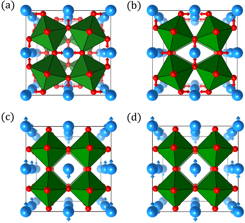
Most ABO3 perovskite oxides present structures that are distorted versions of the ideal cubic phase. In the vast majority of compounds, this distortion is characterized by concerted, short-period rotations of the O6 oxygen octahedra that constitute the basic building block of the perovskite lattice.Glazer (1972); Lufaso and Woodward (2001) The most common rotation patterns can be described as being exactly antiphase [usually denoted with a “” sign, see Fig. 1(a)] or in-phase [“”, see Fig. 1(b)], and often appear together. Indeed, about half of the perovskite oxides present the so-called GdFeO3-type structure,Lufaso and Woodward (2001) an orthorhombic polymorph with space group characterized by antiphase rotations about the [110] pseudo-cubic axis and in-phase rotations about [001]. This structure is usually termed “” in the notation introduced by Glazer,Glazer (1972) which is self-explanatory. Other common structures present only antiphase tilts, and typically adopt tetragonal (, space group) and rhombohedral (, space group) symmetries.Glazer (1972) All these purely-rotational phases are sometimes called antiferrodistortive (AFD), and all are ferroelastic.Salje (1993, 2012) The O6 rotations sometimes coexist with other primary distortions, as e.g. cation off-centerings that give rise to ferroelectricity.Lines and Glass (1977); Rabe et al. (2007) Notably, this is the case of materials like room-temperature multiferroic BiFeO3.Catalan and Scott (2009) Such a coexistence is rare, though, as the ferroelectric (FE) and AFD instabilities are known to compete against each other in the most typical situations.Zhong and Vanderbilt (1995); Kornev et al. (2006); Wojdeł et al. (2013); Gu et al. Hence, most FE perovskites (e.g., BaTiO3, PbTiO3, KNbO3) do not present any O6 tilts at all.
The tendency of perovskites to display O6 rotations is usually explained in terms of the so-called tolerance factorGoldschmidt (1926)
| (1) |
where , , and are the nominal ionic radii of the A, B, and O species, respectively. (Which we typically take from Ref. Shannon, 1976.) This quantity is defined so that corresponds to the ideal case in which rigid spheres with the radii of the corresponding ions are perfectly stuck in the cubic perovskite lattice. In contrast, if , the cubic lattice is in principle unstable. In particular, values imply that the A cation is small as compared with the cage of surrounding oxygens, so that, most likely, a distortion will occur to optimize the A–O bond distances. Typically, rigid rotations of the O6 octahedra are the most favorable possible distortions, and thus structures with tilts abound.
Octahedral tilts characterize many of the most important perovskite compounds, including all the manganitesDagotto (1993) and nickelatesCatalan (2008); Middey et al. (2016) that attract great interest because of their peculiar magnetic, conductive, and magnetoresistive properties. Most of the today much-studied iridates,Rau et al. (2016) where Ir is a relative large cation at the B site of the perovskite lattice, present tilted phases as well, and so do the orthoferritesBousquet and Cano (2016); Zhao et al. (2016, 2017) that have recently gained renewed attention because of their multiferroic and spin-dynamical properties. Moving beyond the oxides, there are plenty of materials families displaying tilted phases, as e.g. the novel hybrid perovskites with incredible photovoltaic properties.Grätzel (2014) Interestingly, the tilting distortion is known to be the key structural factor controlling the electronic properties of all these compounds, as it determines the overlap between the orbitals of the anion and B-site cation (often a transition metal in perovskite oxides).Goodenough (1963) Hence, today there is a great interest in understanding the details of such distortions, and in exploring new possibilities to tune them, as illustrated by many recent works on epitaxial oxide thin films.Schlom et al. (2007, 2014)
Additionally, it has been recently demonstrated that tilted structures provide an unconventional, and in some respects advantageous, strategy to obtain polar, potentially ferroelectric, materials. This so-called hybrid improper ferroelectricityBenedek and Fennie (2011); Bousquet et al. (2008) has been predicted in short-period superlattices based on compounds,Rondinelli et al. (2012); Mulder et al. (2013); Zhao et al. (2014a) and could be a convenient route to obtain elusive effects such as room-temperature magnetoelectricity.Benedek et al. (2012); Zanolli et al. (2013); Zhao et al. (2014b) Experimental demonstrations of this exotic form of ferroelectricity are starting to appear,Oh et al. (2015); Kim et al. (2016) and highlight once again the importance of understanding O6 rotational patterns in perovskites, even in contexts where their relevance was difficult to anticipate a priori.
Given the obvious interest of these tilting distortions, it is surprising to note that they remain relatively poorly studied, especially when compared with the FE instabilities of compounds like BaTiO3 or PbTiO3. For example, while there is an exhaustive crystallographic literature on O6-rotational patterns,Glazer (1972, 1975); Woodward (1997a, b); Stokes et al. (2002) there are very few phenomenological works discussing the energetics and phase transitions of materials with tilted phases. Historically, this is probably related to the fact that these structures (especially those with the space group) tend to be very stable in wide ranges of temperature and pressure, including ambient conditions, which renders them a relatively uninteresting subject of study a priori. First-principles theory is somewhat underdeveloped as well. Admittedly, there are a number of recent works on how to control O6 rotations by epitaxial strain in thin films of specific compounds,Rondinelli et al. (2012) and tilts are the focus of other investigations in various contexts. Yet, in our view we are still missing a thorough first-principles study of these instabilities, and of why some rotational polymorphs prevail over others. For the sake of comparison, in the case of ferroelectric perovskites, the basic first-principles works at the origin of our current understanding, which enabled much of the later progress in FE thin films and strain engineering, were laid out in the early 90’s.Cohen (1992); King-Smith and Vanderbilt (1994); Posternak et al. (1994) In our view, especially relevant were seminal contributions as that of King-Smith and Vanderbilt in Ref. King-Smith and Vanderbilt, 1994; these authors ran a comparative study of a group of representative compounds, and quantified trends in the framework of a simple energy model, which allowed them to rationalize the factors controlling why apparently similar materials present different ferroelectric phases. Our purpose in this work is to provide the same kind of description and insights in what regards octahedral tilts in perovskite oxides.
The paper is organized as follows. In Section II we introduce the formalism that allows us to model the potential energy surface (PES) of a perovskite, around the reference cubic structure, as a function of antiphase and in-phase O6 rotations and cell strains. We discuss the relevant critical points of the PES and their stability. In Section III we describe our first-principles computational approach, and justify the choice of the materials considered in this investigation. In Section IV we present and discuss our computational results. Finally, in Section V we summarize our conclusions.
II Formalism
In this Section we introduce a general model to describe the PES of any perovskite, around the ideal cubic phase, as a function of short-period rotations of the oxygen octahedra and macroscopic strains. This approach is a direct application to rotational distortions of the methodology described in Ref. King-Smith and Vanderbilt, 1994, and our derivations are essentially identical to those described in Ref. Gu et al., 2012 within an investigation of CaTiO3.
The formalism below applies to the idealized case of an infinite, periodic crystal that is free of defects. Further, some important physical effects are not treated in our theory. For example, we ignore the possibility of having spin-ordering transitions – as occurring, e.g., in the considered orthoferrites and orthochromitesBousquet and Cano (2016); White (1969) – and the way those could affect the energetics of the tilting distorions; in fact, we implicitly assume that the materials always remain in their magnetic ground state. Thus, while these simplifications are acceptable for the present study, one should bear in mind that, in order to address more complex phenomena, the present models would need to be extended. (See Refs. Zhao et al., 2016, 2017 for examples of models including magnetostructural couplings.)
II.1 Relevant potential energy surface
We express the energy as a Taylor series, in terms of the relevant structural distortions, around a reference cubic structure. More precisely, we write:
| (2) |
where is the energy of the ideal perovskite cubic phase with a 5-atom periodically-repeated cell, as obtained from a symmetry-constrained first-principles structural relaxation; is the elastic energy as a function of the homogeneous strains , with in Voigt notation;Nye (1985) is the energy associated to antiphase rotations of the oxygen octahedra about the pseudo-cubic axes, as quantified by ; is the analogous function for the in-phase O6 rotations, as given by with ; gathers the anharmonic interactions between antiphase and in-phase tilts; finally, – where “sp” stands for strain-phonon – accounts for the coupling between AFD modes and strains. Let us note that the rotation amplitudes and are associated to distortion patterns as those indicated in Figs. 1(a) and 1(b), respectively. Note also that our choice of notation for the antiphase () and in-phase () rotations reflects the fact that these distortions are respectively associated with the [] and [ for in-phase rotations about the axis] -points of the Brillouin zone corresponding to the ideal 5-atom perovskite cell. Note that and are zone-boundary wave vectors, and is the lattice constant of the 5-atom elemental cell as obtained from a symmetry-constrained relaxation of the cubic reference structure.
This energy must be invariant with respect to the symmetry operations of the cubic phase, which greatly simplifies its form. In the following we write the various terms, truncating the Taylor series at the lowest order that makes it possible to discuss the structural instabilities and their most relevant couplings. Thus, for example, for the elastic energy we have
| (3) |
where the parameters are the usual elastic constants. Note that, because of the cubic symmetry, we have , etc., which allows us to write in a very compact way.
Similarly, it is possible to show that the energy changes associated to antiphase rotations are given by
| (4) |
where and . Note that the existence of antiphase rotational instabilities of the cubic structure translates into a negative value of , which requires us to consider fourth-order terms so that can be bounded from below and the low-symmetry minima well defined. Note also that the term associated to only depends on the modulus , and is therefore isotropic; in contrast, captures the anisotropy energy, and its sign will determine the preferred alignment of the antiphase rotation axis.
Interestingly, the expression for is formally identical to the one corresponding to the energy change as a function of a three dimensional polarization vector.King-Smith and Vanderbilt (1994) Further, it can be shown that also has the same functional form; we have
| (5) |
where and .
As regards the interactions between and , we will restrict ourselves to the lowest-order couplings, which are given by
| (6) |
Note that this lowest-order interaction term is anharmonic; the antiphase and in-phase rotations are decoupled at the harmonic level, which is a direct consequence of their being associated to different -points.
Finally, we consider only the lowest-order terms of the interaction between AFD patterns and strain, which are
| (7) |
Note that the form of the strain-phonon couplings is slightly different for antiphase and in-phase tilts, as the former present a low-order coupling with the shear strains while the latter do not. Indeed, coupling terms of the type are not invariant under the translations of the cubic lattice, which can be immediately seen by noting that the and tilts are associated, respectively to the and -points, while the shear strain is a zone-center distortion. (Some authors include in the expression for the energy the coupling that we would denote in our notation;Gu et al. (2012) yet, such a coupling is identically null by symmetry.)
Our expression for the PES of perovskite compounds with O6-rotational instabilities is thus complete. Note that, thanks to the cubic symmetry of the reference structure, the list of independent couplings controlling the behavior of these materials is relatively short. We have three in , three in , three in , two in , and five in .
II.2 Strain-renormalized energy function
The cubic phase of simple ABO3 perovskites tends to be stable against homogeneous strain deformations, so that is always positive. (More precisely, this implies that , , and .Born and Huang (1954); Karki et al. (1997)) Hence, typically we can treat strains as secondary distortions that simply follow the primary order parameters and . Mathematically, such equilibrium strains can be obtained by imposing the conditions
| (8) |
for . These translate into the set of linear equations
| (9) |
which can be trivially resolved by inverting the matrix:
| (10) |
where
| (11) |
and
| (12) |
Without going into details, let us emphasize that the equilibrium strains depend quadratically on the tilt amplitudes. Hence, if substitute Eq. (10) in Eq. (2), we obtain a simplified expression for a strain-renormalized energy,
| (13) |
where the barred energy terms are formally identical to the unbarred ones described above, but contain modified anharmonic couplings. More precisely, the strain terms in will lead to renormalized and interactions (coming from the part of that is proportional to ), renormalized and couplings (coming from the part of that is proportional to ) and renormalized and couplings (coming from the crossed products between the and contributions to ). As for the term, it is linear in the strain and quadratic in the rotation amplitudes; hence, by imposing , we again obtain additional contributions to the fourth-order couplings in , , and . As a result, the energies , , and in Eq. (13) have exactly the same functional form as their respective counterparts in Eq. (2), but with renormalized fourth-order couplings.
Note that it is possible to solve this problem analytically, as done in the Appendix A of Ref. King-Smith and Vanderbilt, 1994 for an analogous case. Let us also mention that the previous derivation is essentially identical to the stress-free boundary conditions discussed in the Appendix of Ref. Gu et al., 2012, where explicit expressions for the renormalized coefficients are given.
II.3 Main singular points of the energy surface
Let us now discuss the most important structures that may constitute minima or saddle points of the renormalized energy in Eq. (13). We leave strains out of the following discussion for simplicity, noting that it is always possible to obtain them from the rotation amplitudes by using Eq. (10).
II.3.1 Structures with antiphase rotations
First, let us consider phases characterized by antiphase rotations alone. As done in Ref. King-Smith and Vanderbilt, 1994 for the formally similar case of the electric polarization, let us distinguish three different types of solutions.
structures.– We can have phases with , denoted in Glazer’s notation. Note that, equivalently, could be (anti)parallel to the [010] or [001] pseudo-cubic directions; hence, we have six symmetry-equivalent states of this kind. Such structures have tetragonal symmetry with space group , the low-temperature phase of SrTiO3 being a representative example. By substitution in Eq. (13), we find that the energy of such a state is given by
| (14) |
which can be minimized to render a singular point characterized by
| (15) |
and
| (16) |
Note that here we are assuming , so that the antiphase O6 rotations constitute a structural instability of the cubic perovskite phase. We also assume , so that there exists an optimum rotation amplitude that minimizes the energy. Finally, note that we do not mark with a bar, as this is the actual energy of the strain-relaxed state, i.e., it is exactly the same result we would obtain by working with Eq. (2).
The stability of this solution can be readily analyzed by computing the Hessian matrix for at and . Let us consider states given by and . The 6-dimensional Hessian associated to the and perturbations has the diagonal form
| (17) |
where
| (18) |
From these results, a few interesting conclusions immediately follow. As regards the antiphase rotations, we naturally have that the state is stable against parallel perturbations, since . In contrast, the stability with respect to transversal perturbations depends on the sign of : a positive value indicates that the tetragonal phase is stable against such distortions (), but a negative implies we have a saddle point ().
As regards the in-phase rotations, the solution will be stable against them whenever we have a large enough . A more interesting (and more typical) situation occurs if , i.e., whenever the in-phase tilts are instabilities of the cubic phase. In such a case, the sign of will be positive provided that
| (19) |
This would be a situation in which the competition between antiphase and in-phase rotations, as quantified by the coupling , is large enough so that the presence of the former prevents the occurrence of the latter. Note that only accounts for an isotropic competition between different tilt types, while – which appears in but not in – also includes a directional contribution.
Finally, note that for or we would have a cooperation between different rotational patterns. In such a case the state would not be an energy minimum, unless the in-phase tilt is robustly stable (i.e., and large enough).
structures.– Another important case corresponds to rhombohedral structures like those of LaAlO3 and LaNiO3, with space group , displaying antiphase rotations of equal amplitude about the three pseudo-cubic axes. Equivalently, we can think of a single rotation about [111]. (Note that there are eight symmetry-equivalent states of this type.) The corresponding singular point is given by and with
| (20) |
and
| (21) |
Here we assume that and (with , as mentioned above), so that is well defined. As above, we can study the stability of this solution by computing the corresponding Hessian matrix. We thus consider states given by and , and work with symmetry-adapted distortions so that
| (22) |
It can be proved that the Hessian matrix is diagonal in this basis; we have
| (23) |
where
| (24) |
This result bears obvious similarities with what we obtained above for the state. One interesting observation is that and must necessarily have opposite signs. This implies that, in our fourth-order PES, the and states cannot be energy minima simultaneously, and their relative stability is controlled by the sign of the parameter. Note that this observation is consistent with the discussion in Ref. Vanderbilt and Cohen, 2001 on the conditions for having multiple stable states in potential energy surfaces of the same type as .
structures.– Finally, the last structure of this series is the orthorhombic phase with space group and antiphase rotations of equal amplitude about two pseudo-cubic axes. (This amounts to a rotation about a direction. Note that there are twelve symmetry-equivalent structures of this type.) The corresponding stationary point is defined by and with
| (25) |
and
| (26) |
where, as above, we assume that and with , so that is a real number. To study the stability of the solution, we consider states given by and , and work with symmetry-adapted distortions defined as
| (27) |
In this basis, the Hessian is diagonal and has the form
| (28) |
where
| (29) |
As compared to the two cases above, the main peculiarity of this result lies on the fact that and must necessarily have opposite signs, which implies that the orthorhombic solution cannot be a minimum of the energy in our fourth-order PES.
II.3.2 Structures with in-phase rotations
As regards the states in which only in-phase rotations are condensed – denoted by , , and , respectively –, the situation is exactly analogous to that of the purely antiphase structures. Indeed, since and have the same functional form, our previous discussion can be directly applied to the phases with pure in-phase tilts by simply making the substitution .
II.3.3 The structure
Finally, let us discuss the case of the orthorhombic phase that combines antiphase tilts about [110] with in-phase tilts about [001]. (There are twenty-four symmetry-equivalent structures of this type.) In this case the distortion has the form and , and the energy is
| (30) |
For simplicity, in the following we use . Minimizing this energy renders a structure given by
| (31) |
and
| (32) |
where we use the notation to distinguish this orthorhombic () phase from the simpler “ort” tilt patterns ( and ) discussed above. The energy for this state is
| (33) |
From the previous expressions, it is obvious that in absence of interaction between antiphase and in-phase rotations – i.e., for – the phase reduces to a trivial combination of the orthorhombic and tetragonal states described above. It is also possible to prove that, for the solution to exist, at least one of the rotational modes must be an instability of the cubic phase, i.e., either or , or both of them, must be negative. Indeed, if we have – and given that as required for the energy to be bounded from below –, there is no choice of that can yield a well-defined state.
To study the stability of this solution, we consider the structures given by and , and work with symmetry-adapted distortions defined by
| (34) |
In this basis, the Hessian has the form
| (35) |
where
| (36) |
Note that, at variance with the Hessian matrices introduced above, this one is not diagonal. Indeed, because both and correspond to fully symmetric distortions in the phase, there is a non-zero off-diagonal coupling between them. Naturally, by construction, the phase is stable against such distortions, and this part of the Hessian is positive definite. The stability of the phase thus relies on the parameters , , , and , which should all be positive. It is clear that this will depend on the relative values of the and anharmonic couplings affecting individual tilt patterns (e.g., a positive favoring the configuration over will obviously be helpful), and on the strength of the competing/cooperative interactions between different tilt types (thus, e.g., a positive will be generally beneficial for the stability of the phase). It is worth noting that the existence of the pattern as the ground state also requires that its energy be lower than that of competing polymorphs (, etc.), which imposes additional conditions on the coupling parameters.
We will not analyze here all the possibilities and parameter combinations that may result in the stabilization of the phase. Instead, below we will focus on discussing the parameter values that are typical of actual materials displaying the ground state. As we will see, all the investigated compounds present a rather similar behavior, and a very clear physical picture emerges.
III Computational approach
We use first-principles simulation methods to investigate thirty-five representative perovskite oxides with low-energy structures characterized by O6 rotations. The chosen compounds tend to have small tolerance factors ranging between (ZnSnO3) and (BaZrO3). In some cases, we consider various members of significant materials families – as e.g. for the FeO3 orthoferrites –, so that trends as a function of can be more clearly identified. Note that all the considered compounds are simple ABO3 perovskites with uniquely defined A and B cations. Nevertheless, since the structural properties of perovskite solid solutions of the form (A,A’)(B,B’)O3 tend to depend smoothly on composition (Vegard’s law),Denton and Ashcroft (1991); Bellaiche and Vanderbilt (2000); Íñiguez et al. (2003) we believe that our conclusions should be applicable to such more complex compounds, at least as regards trends dominated by cation size or steric effects.
Note that some of the considered compounds – especially small- ones – may display (anti)polar instabilities of their cubic phase, in addition to the AFD soft modes. In such cases, a complete PES model should include, on top of the description of the tilting modes, an explicit theory of the most important polar order parameters, which would complicate the treatment considerably and remains for future work. Here, all such degrees of freedom are treated implicitly, and they are assumed to follow the primary AFD order parameters in what concerns the discussion of the tilted structures. We should note that, in a few cases, the actual ground state of such materials may be FE, or may combine FE and AFD distortions. However, for the purpose of the present discussion, we will only consider structures in which the AFD modes are the primary order. For example, ZnSnO3 has the ground state structure that is typical of LiNbO3;Inaguma et al. (2008); Benedek and Fennie (2013); Gu et al. further, ZnTiO3 and ZnGeO3 have an ilmenite-type ground state.Inaguma et al. (2014); Ross and Leinenweber (2010) The present discussion does not consider such structures and, thus, is not intended to be a complete investigation of these compounds. Yet, we include them among our studied materials, as they provide us with valuable information on the behavior for very small tolerance factors.
To obtain information about the PES, we run symmetry-constrained structural relaxations corresponding to the following tilt systems: , , , , and . We also optimize the cubic structure to obtain the reference energy , and calculate the elastic constants from the response of this phase to small strains. Further, we run structural relaxations under several constraints – e.g., by imposing the cell optimized for the cubic structure (i.e., ), by disallowing the off-centering displacements of the A cations – to further test the behavior of the investigated materials. Such especial situations are described in detail below.
We fit the bare coupling parameters [Eqs. (2)–(7)] by imposing that our models reproduce the AFD amplitudes, strains, and energies obtained for the relaxed structures. More precisely, the , , and parameters are obtained so as to reproduce exactly and , as well as the zero-derivative condition at the relaxed state. Similarly, , , and are fitted to reproduce , , and the zero-derivative condition at the phase. The , , and couplings are obtained by fitting the the -derivatives of the energy evaluated at the and phases, as well as the derivative of the energy for the structure. Similarly, and are obtained from the -derivatives of the energy evaluated at the and structures. Finally, we fit so that we reproduce the energy and zero-derivative conditions of the phase as well as possible. Additionally, we consider a structure which we distort by hand, imposing a small in-phase rotation about the [100] pseudo-cubic axis, as needed to compute the coupling .
As for the strain-renormalized parameters, we follow essentially the same procedure as above, demanding that the energy given by Eq. (13) reproduces all the features of the relaxed stationary structures, except the strains.
We find that the assumed fourth-order polynomial energy is sufficient to obtain a satisfactory description of the key polymorphs mentioned above for all the materials considered. Most importantly, the interaction parameters and are sufficient to capture the key - coupling, and our models yield values that deviate from the first-principles result by about 2 %, typically. Then, as we will see in Section IV.5, obtaining a quantitatively (very) accurate description of additional polymorphs (e.g., ) may require consideration of higher-order interaction terms; however, this detail is not relevant for our present discussion.
For the first-principles calculations, we use density functional theoryKohn and Sham (1965); Hohenberg and Kohn (1964) (DFT) within the generalized gradient approximation adapted for solids (the so-called “PBEsol”),Perdew et al. (2008) as implemented in the simulation package VASP.Kresse and Furthmüller (1996); Kresse and Joubert (1999) In the case of the considered ferrites, we use a Hubbard- correction of the energy functional, for a better description of iron’s 3 electrons,Dudarev et al. (1998) choosing eV which is known to work well for these compounds;Zhao et al. (2016); Kornev et al. (2007); Diéguez et al. (2011) we also assume the iron spins are in an anti-ferromagnetic arrangement, with antiparallel first-nearest neighbors, mimicking their well-known ground-state magnetic structure.White (1969) For SrRuO3 and LaNiO3, we do not use any Hubbard- correction, and consider a trivial ferromagnetic spin arrangement as starting point of our simulations; for SrRuO3 this yields the magnetic solution that has been obtained in previous DFT investigations of this compound, and basically coincides with the experimental state;Miao et al. (2014) for LaNiO3 our simulations yield a non-magnetic configuration, thus reproducing previous calculations and agreeing well with the experimental result.Gibert et al. (2012); Weber et al. (2016) Nevertheless, one should keep in mind that the adecuacy of a simple DFT treatment is questionable for such challenging compunds and, hence, our quantitative results for SrRuO3 and LaNiO3 should be regarded with some caution. The interaction between core and valence electrons is treated using the projector augmented wave (PAW) method,Blöchl (1994) solving explicitly for the following electrons: O’s 2 and 2; Na’s 2, 2, and 3; Al’s 3 and 3; Ca’s 3, 3, and 4; Ti’s 3, 4, and 3; Cr’s 3, 4, and 3; Fe’s 3, 4, and 3; Ni’s 3, 4, and 3; Zn’s 4 and 3; Ga’s 4, 3, and 4; Ge’s 4, 3, and 4; Sr’s 4, 4, and 5; Y’s 4, 4, 5, and 4; Zr’s 4, 4, 5, and 4; Ru’s 4, 4, 5, and 4; Sn’s 5 and 5; Ba’s 5, 5, and 6; La’s 5, 5, 6, and 5; Pr’s 5, 6, 5, and 5; Nd’s 5, 6, 5, and 5; Sm’s 5, 6, 5, and 5; Gd’s 6, 5, and 5; Dy’s 6, 5, and 5; Yb’s 6, 5, and 5; Hf’s 5, 6, and 5; Ta’s 6 and 5. Electronic wave functions are described in a plane wave basis cut off at 500 eV. All the investigated structures are treated using the same 40-atom Glazer cell, which can be viewed as a multiple of the elemental 5-atom perovskite unit and is compatible with all the AFD patterns of interest here. Brillouin zone integrals corresponding to this cell are computed using a -centered grid of -points. (Note that except for SrRuO3 and LaNiO3 – for which a grid of -points is used – all the considered materials are insulators.) Structural relaxations are stopped when residual forces and stresses are below 0.01 eV/Å and 0.2 GPa, respectively. We checked that these calculation conditions are well-converged and sufficient for our current purposes.
Our results are in reasonable agreement with previous first-principles calculations in the literature. Representative of this are the elastic constants, for which there is plenty of published data for some compounds. For example, for CaTiO3 we obtain GPa, GPa, and GPa from our PBEsol calculations (see Table I). In contrast, a work Long et al. (2013) based on a different generalized-gradient approximation Perdew et al. (1996) reports values of 331 GPa, 96 GPa, and 95 GPa, respectively; while the authors of Ref. Gu et al., 2012 obtained 403 GPa, 107 GPa, and 100 GPa, respectively, when using a local-density approximationKohn and Sham (1965) to DFT. Hence, our numerical results fall within the accuracy that can be expected from first-principles calculations that, besides other technical details, depend significantly on the choice of density functional.
Finally, let us mention some important details for the calculation of structural parameters and coupling constants. As mentioned above, and are the amplitudes of the antiphase and in-phase AFD order parameters, respectively (see Fig. 1). Then, let be the atomic positions corresponding to an arbitrary configuration of our periodically-repeated Glazer cell; here, labels the individual 5-atom cells inside our 40-atom supercell, being the corresponding lattice vectors; labels the atoms inside a 5-atom cell, whose positions in the cubic reference structure are given by ; and label the Cartesian axes, which coincide with the pseudo-cubic directions of the perovskite structure. Then, such a configuration can be expressed as
| (37) |
where we have written the strains in their full tensor form, avoiding the compact Voigt notation. More importantly, Eq. (37) introduces the quantities , i.e., the atomic distortions with respect to the strained reference structure. From these distortions, we obtain the amplitudes and by projecting onto six symmetry-adapted modes associated to each of the three antiphase and three in-phase octahedral rotations. We use modes that are normalized to unity when we sum over atoms in the 40-atom cell. The resulting amplitudes and thus have units of length (we use Å throughout). Hence, the harmonic constants and in our energy function are given in eV/Å2, the 4th-order couplings (, , , etc.) are in eV/Å4, and the 6th-order correction in eV/Å6. As usual, the strains are adimensional, so that the elastic constants are given in eV and the strain-phonon couplings (, etc.) in eV/Å2. Finally, note that all the parameters are normalized so that the functions and give energy per 40-atom cell.
IV Results and Discussion
In the following we present our results and discuss their implications, paying especial attention to the reasons why the structure is the ground state of most perovskite oxides.
IV.1 Raw first-principles results
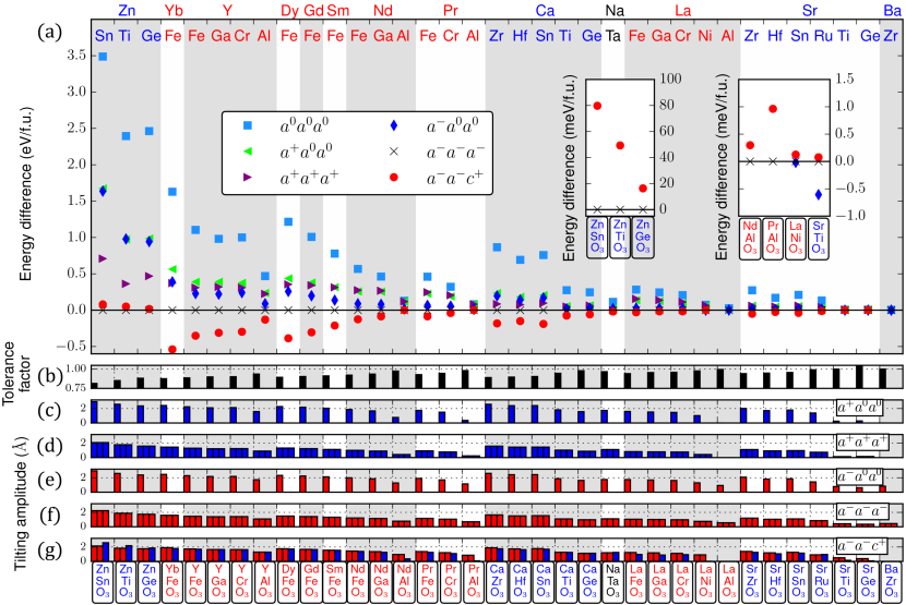
Figure 2 summarizes our raw results, from which many conclusions can be directly drawn. Let us go over them in an orderly manner, and in the next Section we will see how each of them is reflected in (and explained by) the parameters of our energy function.
First, the energy difference between the reference cubic structure and the lowest-energy (ground state) configuration varies strongly with the tolerance factor, from about 3.5 eV/f.u. for ZnSnO3 to less than 5 meV/f.u. for BaZrO3. Correspondingly, there is a decrease of the AFD distortion amplitudes for increasing , although not as drastic; for example, we have 2.3 Å for each of the three components of in the state of ZnSnO3, while we obtain Å in the state of BaZrO3. (These distortion amplitudes may seem unrealistically large; this is a consequence of our choice for the normalization of the associated symmetry-adapted vectors, described above.) Note that the mentioned energy gap – and, to a lesser extent, the distortion amplitudes – are expected to correlate with the temperature at which the cubic phase would transform into the low-symmetry structure, bigger energy differences – or bigger distortions – corresponding to higher-temperature transitions.Abrahams et al. (1968); Wojdeł and Íñiguez (2014) Our results are consistent with the experimental observations in this regard. For example, intermediate- compound CaTiO3 remains tilted up to about 1500 K,Redfern (1996) while LaFeO3 is estimated to become cubic above 2000 K (provided it does not melt first).Selbach et al. (2012) In contrast, the cubic phase of our materials with is stable at rather low temperatures, e.g., down to 110 K in SrTiO3 (Refs. Lytle, 1964; Fleury et al., 1968) and down to essentially 0 K in BaZrO3, for which the symmetry-breaking distortions are probably suppressed by quantum fluctuations.Akbarzadeh et al. (2005) Finally, let us note that, as a consequence of the weaker AFD instabilities, the energy differences between tilt polymorphs become very small for large- compounds; generally, this should result in a greater structural tunability (e.g., by means of epitaxial strain imposed on thin films) in these materials.
Second, for all the investigated compounds, the antiphase O6 rotations render stronger structural instabilities than their in-phase counterparts. Both instability types behave in a much correlated manner, becoming simultaneously stronger, or weaker, as a function of . Interestingly, for , we find compounds in which the -tilts are still a (weak) instability of the cubic structure while the -tilts are not. Examples of this are LaAlO3 and BaZrO3, for which we find it impossible to relax or phases. (In those simulations the compounds relax back to the cubic reference structure; the corresponding results are missing in Fig. 2.) It is not our task here to investigate the atomistic reasons for the general – albeit slight – prevalence of antiphase tilt patterns over in-phase ones; let us note, though, that a discussion of this matter can be found in Ref. Gu et al., .
Third, the phase is not obtained as a distinct solution for two materials, namely, LaAlO3 and BaZrO3. In such cases, during the structural relaxation of the phase – for which we use a typical configuration as starting point – we observe a progressive decrease of the in-phase rotation, until the solution is obtained as final result. Note that these are exactly the same two compounds for which we cannot stabilize structures with only in-phase tilts.
Fourth, the phase is the most stable structure (i.e., the ground state) of the majority of studied materials. On one hand, while our batch of crystals is obviously a limited one, this observation is consistent with reality. Indeed, it is well-known that the phase is dominant among perovskite oxides and, in particular, the number of compounds displaying tilt structures other than is comparatively small.Lufaso and Woodward (2001) On the other hand, if we take into account the points made above, this is a somewhat surprising result. Indeed, our calculations show the preeminence of antiphase tilts over their in-phase counterparts, which suggests that purely antiphase patterns should be dominant over purely in-phase ones (as is indeed the case) and over antiphase/in-phase combinations as well (obviously not the case). Then, to explain why the phase is generally preferred, it would be most natural to imagine some sort of cooperative interaction between antiphase and in-phase rotations, which would drive their simultaneous occurrence. However, our results clearly suggest that, for the state to exist, the in-phase tilts must be a native instability of the cubic structure, which seems at odds with the cooperation hypothesis. Further, if the and rotations were to cooperate, we would expect to see an enhancement of their amplitudes when they appear combined in the phase; however, this is not observed in our results. Hence, the dominance of the ground state is a surprise that we cannot explain from the results presented thus far.
Finally, if we look at the compounds that present lowest-energy structures other than , they clearly belong to two different classes. On one hand, we have a group of large- materials in which the in-phase tilts are either a weak instability of the cubic phase (NdAlO3, PrAlO3, LaNiO3, SrTiO3, and SrGeO3) or not unstable at all (LaAlO3 and BaZrO3). This clearly suggests that relatively strong in-phase tilts are necessary to obtain a ground state. On the other hand, we have small- compounds (ZnSnO3, ZnTiO3, and ZnGeO3) for which all considered AFD distortions are very strong instabilities of the cubic phase. However, for such materials the state lies lower in energy than . Naturally, the reasons behind these results in the small- limit must be quite different from those relevant to large- materials like SrTiO3 or BaZrO3. In particular, it is interesting to note that, as mentioned above, the considered small- Zn-based compounds are not perovskites in reality; thus, one may wonder whether their predilection for other crystalline lattices (LiNbO3-like and ilmenite) may be related to their preference for over .
See Section III for more details on the units and normalization used. For compounds in which the in-phase tilts are not instabilities of the cubic phase (), the corresponding anharmonic and strain-phonon couplings are not given. \chemformZnSnO_3 3.4368 0.2116 0.2853 0.2085 5.1551 2.5882 0.6064 332.02 3.988 3.3607 0.2108 0.2040 0.8413 4.9309 3.7545 962.49 127.55 \chemformZnTiO_3 3.3731 0.2665 0.3163 0.2336 5.6122 2.6985 0.9868 357.63 3.800 3.3629 0.2696 0.2278 1.2845 5.5464 4.2004 913.22 149.10 \chemformZnGeO_3 4.2563 0.3821 0.4359 0.3051 4.0894 1.7946 1.1295 393.32 3.679 4.2129 0.3850 0.2940 1.7780 3.7574 2.7450 800.93 243.53 \chemformYbFeO_3 3.2666 0.2690 0.1914 0.0875 1.2414 0.1461 0.8969 311.61 3.795 2.9343 0.2493 0.1099 1.7128 0.0025 0.1914 999.77 189.83 \chemformYFeO_3 2.6636 0.2525 0.1527 0.0933 0.1725 0.0676 1.2268 323.35 3.827 2.2967 0.2279 0.0634 1.6222 1.2182 0.3470 982.19 216.52 \chemformYGaO_3 2.5675 0.2702 0.1763 0.0824 0.7934 0.2877 1.6840 334.86 3.793 2.1638 0.2466 0.0742 1.7953 2.4215 0.8336 998.33 280.62 \chemformYCrO_3 2.5499 0.2689 0.1936 0.1002 1.5850 0.7523 1.4620 226.79 3.776 2.2363 0.2505 0.0728 1.7821 2.8801 0.0463 1147.72 195.55 \chemformYAlO_3 2.0325 0.3427 0.1882 0.1006 2.8200 1.0237 2.3993 311.32 3.683 1.4610 0.2949 0.0546 2.2546 2.4582 2.5669 1011.53 386.22 \chemformDyFeO_3 2.8305 0.2606 0.1611 0.0918 0.2004 0.0485 1.2369 318.60 3.814 2.4361 0.2352 0.0615 1.6331 1.3442 0.4068 1003.26 213.18 \chemformGdFeO_3 2.5751 0.2549 0.1445 0.0954 0.4067 0.0846 1.4513 321.96 3.825 2.1526 0.2283 0.0335 1.6022 2.1072 0.4935 1001.97 226.86 \chemformSmFeO_3 2.2626 0.2497 0.1267 0.1023 1.2798 0.2075 1.7157 327.46 3.842 1.8100 0.2221 0.0019 1.5536 3.1754 0.7478 1000.37 243.24 \chemformNdFeO_3 1.9300 0.2445 0.1086 0.1135 2.0486 0.4774 2.0031 336.17 3.861 1.4556 0.2192 0.0296 1.4780 4.2207 0.8632 998.83 261.69 \chemformNdGaO_3 1.7823 0.2642 0.1323 0.1039 3.1943 0.7815 2.5818 349.72 3.835 1.2038 0.2335 0.0149 1.6207 6.1151 1.2102 1010.16 323.86 \chemformNdAlO_3 1.0916 0.3501 0.1465 0.1328 5.9629 1.9274 3.4533 339.94 3.733 0.3287 0.3395 0.0224 2.0994 10.5517 2.2041 1019.30 435.80 \chemformPrFeO_3 1.7410 0.2427 0.0974 0.1219 2.5728 0.8180 2.1678 341.47 3.873 1.2481 0.2175 0.0496 1.4386 5.0120 1.1222 998.60 272.66 \chemformPrCrO_3 1.4666 0.2653 0.1461 0.1342 5.2617 0.2739 2.7027 269.95 3.831 0.9582 0.2440 0.0316 1.5880 8.1167 0.3844 1212.03 269.25 \chemformPrAlO_3 0.8632 0.3476 0.1390 0.0389 6.4502 2.0775 3.5909 346.35 3.750 0.0663 0.3276 0.0300 2.3272 12.0365 1.6655 1011.89 443.97 \chemformCaZrO_3 1.6336 0.1440 0.0946 0.1165 1.9993 5.5824 0.0627 250.60 4.123 1.5521 0.1407 0.0840 0.7943 1.6820 5.8031 1265.58 213.56 \chemformCaHfO_3 1.5474 0.1583 0.0994 0.1264 1.6587 6.0322 0.021 248.32 4.064 1.4616 0.1547 0.0891 0.8926 1.2879 6.2055 1323.30 240.74 \chemformCaSnO_3 1.6244 0.1516 0.1082 0.0956 0.3449 3.9340 0.4804 284.04 4.028 1.5623 0.1498 0.0865 0.9434 0.0528 3.9019 1074.87 238.27 \chemformCaTiO_3 1.2063 0.1985 0.0658 0.1376 0.0555 5.1580 0.7306 294.12 3.846 1.0870 0.1917 0.0543 1.2283 0.5534 5.2159 1062.00 281.25 \chemformCaGeO_3 1.3360 0.2840 0.1651 0.1473 4.2548 2.9271 2.1924 313.88 3.739 1.1928 0.2802 0.1128 1.8836 5.3103 2.5564 900.20 361.11 \chemformNaTaO_3 0.4960 0.1530 0.1056 0.1493 2.0430 10.9583 0.8661 227.63 3.946 0.4739 0.1527 0.1173 0.8557 2.0712 11.2295 1482.53 245.99 \chemformLaFeO_3 1.3433 0.2255 0.0650 0.1639 3.0822 0.9321 2.0223 353.27 3.901 0.9311 0.1962 0.0613 1.1851 5.1743 1.0036 983.43 283.46 \chemformLaGaO_3 1.2211 0.2205 0.0738 0.1824 3.8291 1.2673 2.0206 365.85 3.864 0.8453 0.2008 0.0405 1.1222 5.8161 1.3636 986.80 329.12 \chemformLaCrO_3 1.1160 0.2258 0.0937 0.1821 5.4157 0.5899 2.1836 277.65 3.848 0.8144 0.2134 0.0327 1.1975 7.2818 0.3057 1192.41 270.53 \chemformLaNiO_3 0.7139 0.2965 0.1731 0.0779 11.8529 0.0002 4.3395 362.23 3.769 0.2516 0.2542 0.0278 1.9808 14.6453 0.6517 1041.72 296.06 \chemformLaAlO_3 0.4669 0.2925 0.0623 —— 6.9410 1.9893 2.3526 357.29 3.771 0.1136 —— —— —— —— —— 989.05 431.82 \chemformSrZrO_3 0.9691 0.1363 0.0517 0.1242 0.0948 5.5680 0.5546 265.56 4.156 0.8696 0.1327 0.0330 0.7631 0.5006 5.5736 1254.67 258.88
| \chemformSrHfO_3 | 0.8050 | 0.1487 | 0.0538 | 0.1411 | 0.4475 | 5.9698 | 0.7210 | 266.54 | 4.098 |
| 0.6982 | 0.1471 | 0.0335 | 0.8377 | 1.2223 | 5.8840 | 1306.46 | 290.66 | ||
| \chemformSrSnO_3 | 0.9135 | 0.1511 | 0.0722 | 0.1008 | 2.3470 | 3.5175 | 1.3626 | 288.47 | 4.067 |
| 0.7916 | 0.1443 | 0.0350 | 0.9393 | 3.1308 | 3.2244 | 1068.14 | 285.23 | ||
| \chemformSrRuO_3 | 0.9559 | 0.2509 | 0.0953 | 0.2353 | 3.0008 | 2.0584 | 2.4588 | 334.02 | 3.908 |
| 0.8691 | 0.2466 | 0.0428 | 1.3700 | 4.2993 | 0.9725 | 1025.70 | 218.88 | ||
| \chemformSrTiO_3 | 0.1882 | 0.1865 | 0.0242 | 0.1393 | 3.1262 | 4.3480 | 1.8653 | 312.45 | 3.899 |
| 0.0215 | 0.1842 | 0.0614 | 1.3014 | 4.5659 | 4.8710 | 1054.96 | 337.56 | ||
| \chemformSrGeO_3 | 0.2585 | 0.4252 | 0.1934 | 0.0827 | 9.6994 | 1.4051 | 4.2523 | 299.63 | 3.807 |
| 0.0928 | 0.6012 | 0.2004 | 3.6661 | 12.8138 | 0.6900 | 858.38 | 415.25 | ||
| \chemformBaZrO_3 | 0.1135 | 0.1013 | 0.0288 | —— | 2.0365 | 4.2014 | 1.2545 | 303.73 | 4.210 |
| 0.1226 | —— | —— | —— | —— | —— | 1224.42 | 315.85 |
| \chemformZnSnO_3 | -3.3806 | 0.1929 | -0.2745 | -3.3401 | 0.1920 | -0.2001 | 0.1254 | 1.0073 | 0.0066 |
| \chemformZnTiO_3 | -3.3355 | 0.2456 | -0.3045 | -3.3593 | 0.2481 | -0.2241 | 0.1970 | 1.2989 | 0.0131 |
| \chemformZnGeO_3 | -4.2493 | 0.3712 | -0.4268 | -4.2089 | 0.3746 | -0.2912 | 0.2873 | 1.7852 | 0.0489 |
| \chemformYbFeO_3 | -3.2585 | 0.2677 | -0.1936 | -2.9015 | 0.2468 | -0.1180 | 0.0924 | 1.6857 | 0.1643 |
| \chemformYFeO_3 | -2.6538 | 0.2516 | -0.1580 | -2.2627 | 0.2237 | -0.0719 | 0.1011 | 1.5832 | 0.2172 |
| \chemformYGaO_3 | -2.5565 | 0.2688 | -0.1832 | -2.1307 | 0.2400 | -0.0812 | 0.0926 | 1.7445 | 0.2626 |
| \chemformYCrO_3 | -2.5369 | 0.2648 | -0.1934 | -2.1990 | 0.2415 | -0.0724 | 0.1122 | 1.7274 | 0.2086 |
| \chemformYAlO_3 | -2.0270 | 0.3379 | -0.1934 | -1.4619 | 0.2893 | -0.0545 | 0.1032 | 2.2250 | 0.8270 |
| \chemformDyFeO_3 | -2.8213 | 0.2597 | -0.1663 | -2.3976 | 0.2306 | -0.0710 | 0.0996 | 1.5926 | 0.2196 |
| \chemformGdFeO_3 | -2.5649 | 0.2538 | -0.1510 | -2.1130 | 0.2215 | -0.0418 | 0.1048 | 1.5532 | 0.2706 |
| \chemformSmFeO_3 | -2.2550 | 0.2479 | -0.1324 | -1.7730 | 0.2120 | -0.0073 | 0.1122 | 1.4981 | 0.3831 |
| \chemformNdFeO_3 | -1.9220 | 0.2412 | -0.1143 | -1.4237 | 0.2044 | 0.0319 | 0.1228 | 1.4180 | 0.6398 |
| \chemformNdGaO_3 | -1.7735 | 0.2575 | -0.1356 | -1.1787 | 0.2084 | 0.0385 | 0.1131 | 1.5506 | 0.9400 |
| \chemformNdAlO_3 | -1.0897 | 0.3320 | -0.1375 | -0.3255 | 0.2793 | 0.1199 | 0.1203 | 2.0454 | —— |
| \chemformPrFeO_3 | -1.7331 | 0.2383 | -0.1037 | -1.2218 | 0.1993 | 0.0587 | 0.1290 | 1.3800 | 1.0181 |
| \chemformPrCrO_3 | -1.4609 | 0.2517 | -0.1338 | -0.9464 | 0.2113 | 0.0878 | 0.1476 | 1.5077 | 1.0809 |
| \chemformPrAlO_3 | -0.8618 | 0.3264 | -0.1259 | -0.0666 | 0.2534 | 0.1887 | 0.0345 | 2.2456 | —— |
| \chemformCaZrO_3 | -1.5673 | 0.1146 | -0.0797 | -1.4956 | 0.1107 | -0.0664 | 0.0876 | 0.7610 | 0.0320 |
| \chemformCaHfO_3 | -1.4884 | 0.1259 | -0.0797 | -1.4151 | 0.1225 | -0.0660 | 0.0992 | 0.8508 | 0.0456 |
| \chemformCaSnO_3 | -1.5851 | 0.1333 | -0.0909 | -1.5194 | 0.1304 | -0.0669 | 0.0900 | 0.9035 | 0.0566 |
| \chemformCaTiO_3 | -1.1794 | 0.1692 | -0.0337 | -1.0602 | 0.1598 | -0.0133 | 0.1370 | 1.1456 | 0.3083 |
| \chemformCaGeO_3 | -1.3153 | 0.2472 | -0.0838 | -1.1631 | 0.2342 | -0.0133 | 0.1885 | 1.7293 | 0.4665 |
| \chemformNaTaO_3 | -0.4816 | 0.0780 | -0.0418 | -0.4708 | 0.0777 | -0.0499 | 0.0693 | 0.7900 | 0.0364 |
| \chemformLaFeO_3 | -1.3379 | 0.2197 | -0.0667 | -0.9151 | 0.1777 | 0.0782 | 0.1649 | 1.1464 | 2.3807 |
| \chemformLaGaO_3 | -1.2144 | 0.2117 | -0.0720 | -0.8300 | 0.1786 | 0.0618 | 0.1794 | 1.0847 | 1.9170 |
| \chemformLaCrO_3 | -1.1087 | 0.2113 | -0.0790 | -0.8049 | 0.1863 | 0.0803 | 0.1884 | 1.1390 | 0.8844 |
| \chemformLaNiO_3 | -0.7014 | 0.2076 | 0.0001 | -0.2457 | 0.1172 | 0.3008 | 0.1599 | 1.6352 | —— |
| \chemformLaAlO_3 | -0.4662 | 0.2672 | -0.0303 | 0.1136 | —— | —— | —— | —— | —— |
| \chemformSrZrO_3 | -0.9428 | 0.1087 | -0.0230 | -0.8419 | 0.1033 | 0.0012 | 0.1166 | 0.6996 | 0.1392 |
| \chemformSrHfO_3 | -0.7871 | 0.1184 | -0.0161 | -0.6790 | 0.1147 | 0.0115 | 0.1377 | 0.7645 | 0.2838 |
| \chemformSrSnO_3 | -0.8969 | 0.1297 | -0.0317 | -0.7701 | 0.1198 | 0.0123 | 0.1183 | 0.8592 | 0.2798 |
| \chemformSrRuO_3 | -0.9374 | 0.2306 | -0.0741 | -0.8382 | 0.2202 | 0.0633 | 0.2549 | 1.2706 | 0.4282 |
| \chemformSrTiO_3 | -0.1857 | 0.1544 | 0.0441 | -0.0215 | 0.1818 | 0.0606 | 0.1559 | 1.2345 | —— |
| \chemformSrGeO_3 | -0.2552 | 0.3382 | 0.0040 | -0.0928 | 0.5876 | 0.1956 | 0.0887 | 3.5973 | —— |
| \chemformBaZrO_3 | -0.1101 | 0.0789 | 0.0079 | 0.1226 | —— | —— | —— | —— | —— |
IV.2 Modeling the relevant potential energy surface
Next, we use the results described above to fit the parameters defining the relevant PES, following the guidelines given in Section III. Table I shows the results obtained for the parameters entering the energy of Eq. (2), where strains are explicitly considered. In contrast, in Table II we present the results obtained for the parameters that implicitly capture the strain relaxations that follow the primary orders and , corresponding to Eq. (13). Finally, Fig. 3 displays the key couplings in a way that makes it easier to appreciate trends as a function of the tolerance factor. For simplicity, in this Section we focus on the strain-renormalized results to discuss the main features of the PES. The computed parameters reflect and explain the conclusions drawn above by direct inspection of our raw first-principles results, and also yield a number of additional insights.
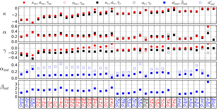
First, the strength of the AFD instabilities for small- compounds is reflected in the large negative values of and , which get closer to zero (and eventually become positive) as the tolerance factor increases. Note that, in principle, a large energy difference between the AFD phases and the cubic reference might also originate from small anharmonic couplings and [see Eqs. (16), (21), (26), and (33)]. However, these parameters do not present any marked or systematic variation with , and remain in the range between 0.1 eV/Å4 and 0.5 eV/Å4 for all investigated compounds.
Second, we find for all the investigated materials, reflecting the fact that the antiphase rotations constitute stronger structural instabilities of the cubic phase than their in-phase counterparts. Describing the anharmonic couplings is not as straightforward. Roughly, we find that the isotropic coupling constants and are similar for all the considered compounds, and that we generally have . In contrast, we tend to have , which is consistent with the dominance of the solution over purely in-phase or other purely antiphase states.
Third, while we obtain for all the investigated compounds, we find two materials (LaAlO3 and BaZrO3) for which . In such cases the in-phase tilts are not instabilities of the cubic phase, and it is thus natural that structures with only in-phase tilts cannot be stabilized, as mentioned above. Hence, our usual fitting procedure does not allow us to compute for these compounds; instead, we obtain it by diagonalizing the Hessian matrix – of second derivatives of the energy – corresponding to the cubic reference structure. Also, as can be seen in the Tables, for LaAlO3 and BaZrO3 we do not compute any anharmonic terms involving in-phase tilts, or the couplings with strains.
Fourth, our calculated parameters allow us to discuss in detail the reasons why the phase turns out to be the ground state of most perovskite oxides. As already mentioned, for all the considered compounds, antiphase tilts render more stable structures than in-phase rotations. Further, our fitted PES clearly indicates that the antiphase and in-phase modes compete with each other, as we get for all studied materials. Hence, it is now clear that the ground state, which combines antiphase and in-phase tilts, does not emerge because of a cooperation between the two types of AFD modes. Rather, the phase prevails in spite of the fact that these two distortions compete and tend to cancel each other.
Let us emphasize this point. Our results clearly show that there is no such thing as a driving force for the simultaneous occurrence of antiphase and in-phase tilts in ABO3 perovskites. Instead, the reason why they appear together in most compounds is somewhat mundane. Indeed, all the investigated materials share the feature that , i.e., they posses similarly strong antiphase and in-phase instabilities of the high-symmetry cubic structure. Thus, in principle such distortions should occur simultaneously, unless their competition is large enough for the strongest () to suppress the weakest (). Our results show that the - competition is not as strong, and thus the two tilt types coexist.
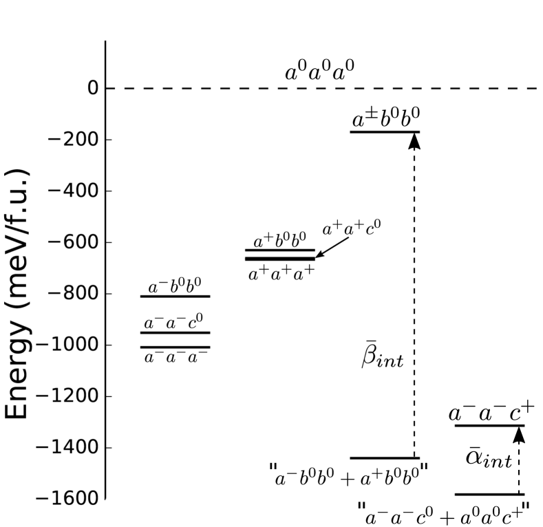
To gain additional insight, and to understand why the antiphase and in-phase tilts appear in the specific combination, let us turn our attention to Fig. 4. The diagram shows the relative stability, with respect to the cubic () phase, of different AFD polymorphs for the representative case of GdFeO3. The dominant antiphase-tilted phase is , closely followed by the structure, which lies about 50 meV/f.u. above it. The structures with only in-phase tilts are about 300 meV/f.u. above the corresponding antiphase-tilted ones, and the energy gap between the most () and least () stable one is about 35 meV/f.u. Now, for the sake of the argument, let us imagine that the and tilts do not interact. In that case, hybrid - states like those indicated in Fig. 4 – namely, “+” and “+”– could potentially be the ground state of the material. Indeed, in absence of - interactions, these two structures can be viewed as a simple combination of antiphase and in-phase distortions, and their energies with respect to the cubic reference would be and , respectively. As shown in Fig. 4, for GdFeO3 this yields energies well below that of the phase, simply because the energy gain associated to the condensation of an in-phase tilt ( in these examples, which is about 630 meV/f.u.) is much greater than the energy cost of rotating the antiphase-tilt axis (i.e., the anisotropy for , as given by meV/f.u., is comparatively small). As long as such a condition is met, having a ground state combining and tilts is in principle possible.
However, antiphase and in-phase tilts do interact repulsively (, ), which will increase the energy of our hypothetical hybrid configurations. The “+” structure will be most strongly affected, as the occurrence of and tilts about the same axis is much penalized by the large coupling . In Fig. 4 we show the energy of such a phase once the - interactions are considered; the result, which we denote , is obviously not competitive with other polymorphs. In contrast, for “+” the active - interaction is given by the relatively small coupling, and the resulting structure () is obviously competitive with the other low-lying polymorphs. In fact, this is the ground state in the case of GdFeO3.
By inspecting the parameters computed in the present investigation, it is apparent that the above picture applies to all the compounds with a ground state considered in this work. Hence, we think this picture is likely to be valid for most perovskite oxides.
Finally, let us turn our attention to the materials that do not present a ground state. In the case of the large- compounds, the situation is quite obvious from the above description. Whenever (LaAlO3, BaZrO3), there is actually no driving force for the occurrence of in-phase tilts, and the polymorph does not exist. Whenever we have a negative but small , we get a polymorph that barely differs from a structure [see Fig 2(g)]. In such cases, the repulsion is often able to push up the energy of the phase and yield a purely antiphase-tilted ground state. We should note that the result may depend on very tiny energy differences in some limit cases; see e.g. the occurrence of a ground state in NaTaO3 ( eV/Å2, eV/Å4), and its absence in NdAlO3 ( eV/Å2, eV/Å4). Yet, the general trends are clear.
In the case of the large- Zn-based compounds, the reasons why we obtain a lowest-lying state, instead of the fully developed polymorph, are totally different. Indeed, by inspecting the parameters in Table II, we find that these materials display the following distinct features affecting the vs competition. On one hand, they present very strong - repulsive interactions, featuring record values for in the case of ZnTiO3 and ZnGeO3. On the other hand, they display, by far, the strongest anisotropies among the investigated compounds, as quantified by and . As a result, antiphase tilts about and axes are strongly penalized compared to the state. The combination of these two factors, particularly the latter, explains why these materials prefer the polymorph. Interestingly, a (huge) antiphase rotation with constitutes the structural path connecting the perovskite and LiNbO3-type structures. Further, we know that, in reality, the considered Zn-based compounds crystallize in the LiNbO3-type phase or the (related) ilmenite structure. Hence, our present results in the small- limit – featuring and – reflect the well-known tendency to abandon the perovskite lattice and move towards a LiNbO3-like structure.Benedek and Fennie (2013) As a by-product of sorts, the phase losses its predominance in this limit.
Note that the above observations can be confirmed by considering the formulae in Section II and the actual parameters obtained for specific materials. For example, it is straightforward to check why the energy of the phase [, Eq. (33)] will be generally lower than that of competing polymorphs: it benefits from the contributions from both antiphase and in-phase distortions, while is relatively small. It is also easy to understand why the solution is a minimum of the energy [Eq. (36)], as this is essentially guaranteed by the positive interaction terms and . Further, it can be readily seen that, whenever , the possible existence of the phase as a singular point is unclear, as we would typically have in Eq. (32) if all the other parameters have values as those computed here. It is true that, from Eq. (32), one might imagine alternative ways to stabilize the phase even if is positive; for example, we might have a strong cooperative interaction , while keeping as the main driving force for the structural instability. Nevertheless, according to our DFT results, all the investigated compounds are far from such alternative scenarios, which thus seem to be highly unlikely.
IV.3 Strain effects
Let us now turn our attention to the elastic energy () and the coupling of strains with the tilt modes (). The corresponding parameters are given in Table I, as obtained from the fit of all the bare coupling constants in Eq. (2).
As regards , the behavior of the investigated materials is standard, the cubic phase being stable against strains. It is interesting to note that there is no clear dependence of the elastic constants on the tolerance factor, suggesting that chemical considerations – as opposed to steric – should be most relevant in this case.
As regards the coupling between strains and AFD modes, we find that the constants , , , and are positive for some compounds and negative for others. Thus, for example, LaAlO3 presents negative values of and , implying that negative strains , , – i.e., a smaller cell volume – will tend to weaken the instabilities; this is compatible with the known behavior of LaAlO3, as it is experimentally and computationally observed that an hydrostatic compression results in a transition from the usual tilted phase of the compound (, ) to a non-tilted structure (cubic ).Bouvier and Kreisel (2002) In contrast, positive values of these strain-tilt couplings imply the opposite effect, that is, an enhancement of the rotational instabilities upon compression; this is the most common behavior, as discussed at length by some of us in Ref. Xiang et al., 2017. In addition, we find that the coupling constant between shear strains and antiphase rotations () varies sign depending on the compound. Finally, it seems all but impossible to identify clear trends of the strain-phonon coupling parameters as a function of tolerance factor, which suggests that other (chemical) factors must play a role in determining their value. This issue, which is the focus of ongoing studies by some of us,Gu et al. falls beyond the scope of this work and will not be pursued here.
Rather, our present interest is to understand how strain affects the relative stability of the tilt phases. To gain insight into this question, we show in Fig. 3 the most important bare parameters [e.g., , , etc., obtained by fitting Eq. (2) to our DFT results] together with their strain-renormalized counterparts [e.g., , , etc., obtained by fitting Eq. (13)]. Note that a difference between bare and strain-renormalized couplings is indicative of a strain relaxation. Our main findings are as follows.
First, for the harmonic parameters and , we obtain essentially the same values from the two fitting procedures, for all investigated compounds. This is the expected result because, provided our fourth-order series is an accurate representation of the relevant PES, we should not have any strain renormalization of the harmonic constants (see Section II.2). Second, the strain renormalization is also negligible for the interaction couplings, so that we have and . This result is not obvious a priori, and indicates that, for the investigated compounds, strain does not play any significant role in the competition between antiphase and in-phase rotations. Third, there is a sizeable renormalization of the and parameters for some of the compounds studied (e.g., NaTaO3), although the effect has no qualitative significance. Note that we always have and , i.e., the strain results in larger tilt distortions by weakening the anharmonic (repulsive) interaction. This is easy to understand: For given values of and , the energy for fixed (zero) strains will be higher than the one obtained if we allow the strains to relax in response to the tilts. The former case is captured by the bare couplings, and the latter by the strain-renormalized ones; the mentioned energy reduction corresponds to having and strictly smaller than and , respectively. Finally, the anisotropy terms and also exhibit a significant strain renormalization for some compounds, although the effect is generally small. In this case, we have no definite expectations on the behavior of the renormalized parameters and, indeed, our findings do not show any obvious systematics. It is worth noting that, in cases in which or is close to zero, the strain relaxation may cause the coupling to change sign, and thus reverse the relative stability of the tetragonal (e.g., ) and rhombohedral (e.g., ) structures (see Section II.3). According to our results, SrGeO3 presents this behavior ( eV/Å4, eV/Å4), and NdAlO3 and PrAlO3 are borderline cases. This extreme sensitivity to strain is best characterized theoretically in ferroelectric PbTiO3,King-Smith and Vanderbilt (1994); Wojdeł et al. (2013) and our results here provide an AFD analogue of such an effect.
Hence, while strains do have some impact on our investigated PES, the effects are of little importance to the central question here, i.e., the preeminence of the structure among perovskites. Indeed, strain effects – which are negligible for the interacting constants and – are largely irrelevant in that respect. Let us note that we corroborated this conclusion by repeating the computational investigation of our thirty-five compounds, considering all the AFD polymorphs mentioned above, under the constraint of zero strains. (We thus impose that the lattice vectors be fixed at the values obtained from the symmetry-constrained relaxation of the cubic structure.) By fitting Eq. (13) to the DFT data thus computed, we obtain parameters that are qualitatively identical, and quantitatively very similar, to our strain-renormalized results in Table II. Hence, strains will not be further considered here.
IV.4 A-site antipolar distortions
Antipolar displacements of the A cations, as those shown in Fig. 1, have been found to play an important role in stabilizing the structure over competing polymorphs in some compounds.Benedek and Fennie (2013); Diéguez et al. (2011); Miao et al. (2014) In this Section we discuss how such modes can be treated, and their effect quantified and analyzed, within our present scheme.
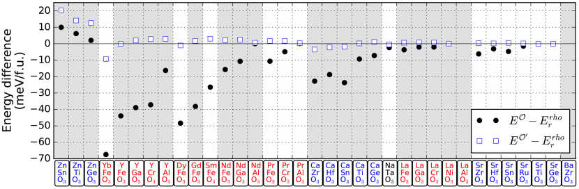
Let us first test the importance of the antipolar distortions by performing the following computational experiment: For all the materials considered here, we repeat the relaxation of the structure under the constraint that the A-cations be frozen in their high-symmetry positions. In other words, we impose null antipolar distortions and thus preclude the possibility that the A-cations may move off-center to optimize the energy of the phase. In the following we will refer to such a constraint as “frozen-A”, and the quantities computed in frozen-A conditions will be primed. Figure 5 summarizes our findings, showing how the energy difference between the and structures varies depending on whether the antipolar modes are allowed or not. The results are crystal clear: We observe that, for most of the considered compounds, the and phases become nearly degenerate in frozen-A conditions. Further, we typically have , so that the structure becomes the lowest-energy state. Hence, previous observations in the literature get confirmed: the antipolar A-cation distortions are essential for the preeminence of the ground state among perovskite oxides. In their absence, most compounds would present an ground state.
These antipolar distortions can be thought of as secondary modes that follow the primary and order parameters in the same way that strain does. Hence, the antipolar modes are naturally present whenever we relax the phase for any of the considered compounds; they couple to the octahedral tilts and strains, and thus contribute to the resulting structure and energy of the phase. Consequently, the effect of these modes is implicitly captured when we fit the parameters describing the relevant PES to DFT data. Note that this interpretation of the antipolar distortions as secondary modes is strictly correct only for compounds that do not present antipolar instabilities of the cubic phase, as is the case of the majority of materials here considered (see discussion in Section III and below). It is also important to realize that, from all the AFD polymorphs discussed above, such antipolar distortions appear only in the structure; in fact, it can be checked that none of the simpler phases considered here, for which we have either or , presents any secondary distortions besides strain.Bellaiche and Íñiguez (2013)
Since the antipolar distortions are treated implicitly in our PES description, we can view our calculated parameters in Tables I and II as being renormalized by these modes. Nevertheless, we can go further and explicitly study such a renormalization by recalling the relevant couplings between antipolar and AFD modes, which have been discussed elsewhere.Bellaiche and Íñiguez (2013) For simplicity, in the following we consider the particular variant of the phase, noting that the results for other, equivalent structures – e.g., the one described by – can be obtained directly by suitable symmetry transformations.
There are two antipolar modes associated to off-centering displacements on the A-cations. In the following we discuss at length the first and most relevant of them, which yields the largest structural distortions and associated energy reductions. We will briefly discuss the second one at the end of the Section.
The first antipolar mode features movements of the A cations along the [110] pseudo-cubic direction, spatially modulated according to the wave vector [see Fig. 1(c)]. This mode involves an homogeneous pattern of [110]-oriented dipoles in a given (001) plane, and the reversal of such dipoles as we move by one elemental cell along the [001] direction. Let be the amplitude of this distortion. Following Ref. Bellaiche and Íñiguez, 2013, one can prove that its lowest-order coupling with the AFD modes has the form
| (38) |
where is a material-dependent constant and we assume that the state is characterized by
| (39) |
Let the energy associated to this antipolar mode be given by
| (40) |
with , as it corresponds to a regular distortion that is not an instability of the cubic phase. [If were negative, we would need to introduce terms in .] We can add and to the energy in Eq. (2) and, in analogy to our treatment for the strain in Section II.2, impose the equilibrium condition
| (41) |
which yields the distortion
| (42) |
If we substitute this result into the above expressions for and , we obtain
| (43) |
where there is no explicit dependence on the antipolar mode amplitude. Now, by recalling the form of the energy for an state [Eq. (30)], we can see that the coupling term stemming from contributes exclusively to the anharmonic interaction constant . [If we work with the full expression for the energy (Eq. 2), we trivially find that the renormalized anharmonic coupling is . Further, if we write the full symmetry invariant for the trilinear -- coupling, we obtain a renormalization term proportional to , which contributes to in Eq. (6).]
It is important to note that this contribution to is negative. In other words, the relaxation favors an attractive, cooperative anharmonic interaction between antiphase and in-phase tilts. As a consequence, it tends to stabilize structures that combine both types of tilts about certain specific axes (e.g., and in our case), and will result in larger tilt amplitudes and a lower energy .
We can test this theoretical prediction numerically. As mentioned above, we have DFT results for relaxed phases in absence of antipolar distortions (frozen-A conditions). Hence, we can use those data, together with our DFT results for the simpler only-antiphase and only-in-phase AFD states, to compute the coupling constants that describe the corresponding PES. The main outcome of this exercise is shown in Fig. 3, where the effect of the antipolar renormalization on the parameters is clearly visible. (We get no significant difference for the other coupling constants, in agreement with the theoretical expectations.) Indeed, for all compounds we find , where a larger implies a greater - competition. As shown in Fig. 5, such a competition can become strong enough as to yield an ground state.
In view of these findings, we can conclude that the preeminence of the ground state over the polymorph stems from a balance between the tendency of the material to condense both antiphase and in-phase tilts () and the mutually-exclusive interaction between them (). This balance is a delicate one. Indeed, as shown in Fig. 5, it typically involves small energy differences meV/f.u., the phase being dominant in frozen-A conditions. Then, the extra energy reduction provided by the relaxation of antipolar modes () is usually enough to tip the balance and stabilize the ground state.
Finally, let us comment on the second antipolar mode occurring in the phase [Fig. 1(d)], which involves displacements of the A-cations along the pseudo-cubic direction, modulated according to the wave vector. Following Ref. Bellaiche and Íñiguez, 2013, we know that the leading coupling responsible for the activation of this secondary mode has the form
| (44) |
where is the amplitude of the -modulated antipolar distortion and is a material-dependent coupling constant. Assuming that the energy of this mode is given by
| (45) |
with , the tilt-dependent equilibrium value of is
| (46) |
and its contribution to the energy is
| (47) |
This result is similar to the one obtained above for the distortion. In fact, the qualitative effect of this second antipolar renormalization – i.e., to favor the simultaneous occurrence of antiphase and in-phase tilts – is exactly the same. There is one important difference, though: Relaxing the mode affects a sixth-order interaction between the tilts, a coupling that is not included in our fourth-order model of the relevant PES. Since our numerical results regarding the vs competition seem perfectly consistent with a fourth-order Taylor series, we can conclude that the effect of this second antipolar renormalization is probably small. Hence, we do not pursue this issue further in this work.
IV.5 Additional remarks
Let us conclude with some additional comments on our results.
IV.5.1 Energy landscape, sixth-order corrections
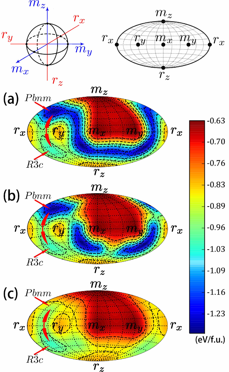
The above discussion focuses on the relative stability of the lowest-energy AFD polymorphs, i.e., the and phases. Nevertheless, from the PES given by our fitted , we have access to the full six-dimensional energy landscape and can thus explore its features. To do this, we find it convenient to implement the special stereographic projection shown in Fig. 6. We work with a three-dimensional Cartesian system, with coordinates , in which a positive value of () correspond to a positive (negative) value of . We can further define the two-dimensional surface obtained by minimizing the energy along the radial coordinate , and make a stereographic projection of the result. We can thus inspect the PES regions in which the energy is lowest. Figure 6(a) shows the energy map thus obtained for representative compound GdFeO3.
Before commenting on the features of this landscape, let us note the low-energy (dark blue) path displayed by Fig. 6(a), which connects the following string of structures: , where we start from the () phase indicated with an arrow in the figure and, as we move to the right and down, end up in an equivalent structure. According to our fitted 4th-order PES, all the structures along this path are rather low in energy; in particular, the phase is predicted to the second most stable polymorph of GdFeO3, only behind the ground state, and lying lower than the phase. This is a surprising result, as the tilt pattern is quite rare in nature; hence, we run first-principles simulations to verify it. Interestingly, the DFT simulations reveal that our 4th-order model – fitted to account for the – competition, as explained above – exaggerates the stability of the polymorph by about 240 meV/f.u.; in fact, we find that, at the DFT level, the phase lies above the structure by about 40 meV/f.u.
This result indicates that our 4th-order model is not sufficient to account for the details of the - interactions in a quantitatively accurate way. In hindsight, this finding is not surprising. For GdFeO3, and for most of the compounds considered here, the tilt amplitudes are very large, and it is natural for couplings above 4th-order to play a role. Specifically, our DFT result for the -type structures can be easily reproduced by extending the model with an additional 6th-order coupling of the form
| (48) |
which has the peculiarity of having no effect at all on the energy and stability of all the polymorphs discussed above. (For the coupling to be active, at least two in-phase tilt components must be different from zero.) We find that for eV/Å6 we recover the DFT result for the energy of GdFeO3’s structure. The corrected energy yields the landscape shown Fig. 6(b). The new map is overall quite similar to that of Fig. 6(a), except that the -like phases are relatively high-energy saddle points now.
It is apparent from this map that the and states both constitute energy minima, and that such minima are connected by a low-energy saddle point. Simple tetragonal structures, like those corresponding to the points marked and , are relatively high-energy saddles that appear as local maxima in our projection (for such states the energy is convex only along the radial direction ); in contrast, the orthorhombic structures and are lower-energy saddles, reflecting that we have for this material. A peculiar case is that of the state, e.g., the mid point between and in Fig. 6(b): Note that an -distortion reduces the energy of such a structure, as it takes it towards the ground state; in contrast, an -distortion increases the energy, as in this case the condensation of a new in-phase rotation (, ) cannot compensate for the increase in - repulsion ().
In Fig. 6(c) we show the stereographic projection of the PES of GdFeO3 obtained under the frozen-A constraint. (This PES includes a small 6th-order correction term with eV/Å6.) As compared with the actual PES [Fig. 6(b)], the most significant changes occur in the vicinity of the state. Indeed, the increased competition results in the near disappearance of the minimum and the consolidation of the ground state. Note also that the energy of other phases involving A-cation relaxations – e.g., the and structuresBellaiche and Íñiguez (2013) – increases significantly in frozen-A conditions, while, in contrast, the purely antiphase or in-phase states (e.g., , remain unaltered.
Let us conclude this part by noting that the issue discussed above for GdFeO3 – i.e., the exaggerated stability of the structure, as predicted by the default 4th-order model – is general among the compounds studied in this work. Indeed, we used our DFT methods to relax the phase of all investigated materials, and found that the error in the energy predicted by the 4th-order model tends to grow as the tolerance factor decreases. (It can be as large as 400 meV/f.u. for YbFeO3.) This is a reasonable result: smaller- compounds display larger tilts and, as a consequence, higher-order energy terms should become more relevant for an accurate PES description. Following the recipe described above, we can compute for all the investigated compounds that present a stable phase; the results are given in Table II.
These results show that our fourth-order models – which are sufficient to reproduce the low-lying PES accurately, and whose simplicity allows satisfying physical interpretations – perform poorly when it comes to predict the energies of less-favorable states. While this seems an acceptable compromise in the present study, such an inaccuracy might become a problem if, for example, these same models were used to predict the behavior of the materials under the action of fields (epitaxial stress Pertsev et al. (1998), electric Stengel and Íñiguez (2015)) that can be expected to stabilize unusual phases. Indeed, our results suggest that, generally speaking, one should validate low-order potentials before using them for quantitative investigations of materials subject to significant perturbations.
IV.5.2 More on the phase diagram
To conclude, let us comment on the scope of the present investigation as regards a full discussion of the phase diagram of these perovskites. In this work we compare the relative stability of different structural phases by inspection of their energies, as directly obtained from DFT simulations. We focus on discussing the character of the ground state structure, and are thus confined to the limit of very low temperatures (strictly speaking, to 0 K). Then, it is worth noting that, for the prediction of the ground state to be more accurate, one should add the zero-point contribution to our computed static energies. Yet, here we leave zero-point energies out of the discussion, essentially for two reasons: First, they are not defined for many of the considered structures, which are saddle points of the PES and thus have imaginary-frequency phonons associated to them. Second, they depend on the soft modes of the material as much as (actually, less than) they depend on the harder ones; hence, the discussion of zero-point energies has little to do with the PES of the tilt modes, which is our main focus in this work.
To these main reasons, let us add the expectation that, because all the AFD phases of a given compound share the same kind of lattice topology and chemical bonding, zero-point energies should not be strongly polymorph dependent. It is obvious, though, that we have materials in which the obtained energy gap between different phases is tiny, and in such cases zero-point effects might in principle tip the balance. Nevertheless, the general agreement between our results for the lowest-energy structure and experimental observations (we are not aware of any obvious conflict) suggests that zero-point energies do not play any important role in determining the ground state of these compounds. Let us note that this seems to be the case of most first-principles works with perovskite oxides, as zero-point corrections are seldom considered and, yet, good agreement with experiment is common.Rabe et al. (2007)
Finally, let us briefly comment on how one could investigate the effect of temperature on the competition among different tilt polymorphs. We have two distinct situations. On one hand, whenever we have compounds with well-developed O6 rotations, for which the and structures are local energy minima, it should be possible to account for the effect of temperature by using the well-known quasi-harmonic approximation (see, e.g., Ref. Cazorla and Íñiguez, 2013). This would require accurate and heavy calculations of the phonon spectrum, as a function of volume, from which the temperature-dependent free energy of the different polymorphs can be approximated. Such an approach that has been barely applied in studies of perovskite oxides. Yet, it is interesting to note that a detailed investigation of BiFeO3 (Ref. Cazorla and Íñiguez, 2013) showed that the structure is softer than the polymorph (which is polar, with space group , for this compound), and it becomes favored upon heating. Interestingly, if the occurrence of a relatively soft phase were general in the perovskite family, thermal effects would provide us with yet another reason for the prevalence of the state. Nevertheless, this point should be explicitly verified on a case by case basis, as we do not see any general reasons for the structure to be softer (or harder) than the one.
On the other hand, for compounds with weak tilt instabilities, the phase diagram will probably be determined by mechanisms that are typical of displacive soft-mode transitions. Hence a theoretical discussion will require a treatment of unstable phonon bands that will be, presumably, strongly temperature dependent. To study such cases we would need to resort to effective-potential schemes like e.g. those introduced in Refs. Zhong et al., 1994, 1995; Wojdeł et al., 2013. The few existing studies applying such methods to AFD compounds suggest that subtle interactions control the phase diagram,Wojdeł et al. (2013); Zhong and Vanderbilt (1995); Akbarzadeh et al. (2005) which dissuades us from formulating any general expectations.
V Conclusions
In summary, this article reports on a thorough theoretical investigation of ABO3 perovskite oxides whose structure is characterized by concerted tilts of the O6 octahedra that constitute the backbone of the lattice. Our results provide a clear picture of why one particular tilt polymorph (the pattern, corresponding to the orthorhombic space group) prevails over all other in most perovskite materials; indeed, we are able to identify the physical requirements for such a structure to occur – i.e., antiphase and in-phase tilts are both native instabilities of the cubic perovskite prototype, relatively small anisotropy energy of the antiphase tilts, relatively weak competition between antiphase and in-phase tilts –, which happen to occur very frequently. Our results also prove the critical role played by secondary distortions – antipolar modes involving the A cations – to weaken the antiphase/in-phase competition and yield the ground state. Additionally, we find that the polymorph losses its preeminence in two opposite limits – essentially, for small and large A cations – for completely different reasons, which we discuss in some detail. Hence, beyond corroborating some scattered observations in the literature, this work brings unprecedented insight into (and quantification of) the competition between different tilt phases in perovskite oxides, and we hope will be useful to better understand existing compounds and eventually design new ones.
This work was mainly funded by the Luxembourg National Research Fund through Grants FNR/P12/4853155/Kreisel COFERMAT (H.J.Z. and J.Í.), FNR/C15/MS/10458889 NEWALLS (H.J.Z. and J.Í.), and INTER/MOBILITY/15/9890527 GREENOX (L.B. and J.Í.), and by the Nature Science Foundation of China Grant No. 11574366 (P.C. and B.G.L.) and the China Scholarship Council Grant No. 201504910652 (P.C.). Additionally, we acknowledge support from the ERC Consolidator grant MINT with contract number 615759 (M.N.G. and M.B.) and ARO Grant No. W911NF-16-1-0227 (L.B.). Some figures were prepared using VESTAMomma and Izumi (2011) and matplotlib,Hunter (2007) and we made extensive use of several crystallographic servers.Aroyo et al. (2006a, b, 2011); Campbell et al. (2006); Hatch and Stokes (2003) Useful discussions with Philippe Ghosez and Mael Guennou are gratefully acknowledged.
References
- Glazer (1972) A. M. Glazer, Acta Crystallographica Section B 28, 3384 (1972).
- Lufaso and Woodward (2001) M. W. Lufaso and P. M. Woodward, Acta Crystallographica Section B 57, 725 (2001).
- Salje (1993) E. K. H. Salje, Phase transitions in ferroelastic and co-elastic materials (Cambridge University Press, Cambridge, 1993).
- Salje (2012) E. K. H. Salje, Annual Review of Materials Research 42, 265 (2012).
- Lines and Glass (1977) M. E. Lines and A. M. Glass, Principles and Applications of Ferroelectrics and Related Materials, Oxford Classic Texts in the Physical Sciences (Clarendon Press, Oxford, 1977).
- Rabe et al. (2007) K. M. Rabe, C. H. Ahn, and J. Triscone, eds., Physics of Ferroelectrics: A Modern Perspective (Springer Berlin Heidelberg, Berlin, Heidelberg, 2007).
- Catalan and Scott (2009) G. Catalan and J. F. Scott, Advanced Materials 21, 2463 (2009).
- Zhong and Vanderbilt (1995) W. Zhong and D. Vanderbilt, Physical Review Letters 74, 2587 (1995).
- Kornev et al. (2006) I. A. Kornev, L. Bellaiche, P.-E. Janolin, B. Dkhil, and E. Suard, Physical Review Letters 97, 157601 (2006).
- Wojdeł et al. (2013) J. C. Wojdeł, P. Hermet, M. P. Ljungberg, P. Ghosez, and J. Íñiguez, Journal of Physics: Condensed Matter 25, 305401 (2013).
- (11) T. Gu, T. Scarbrough, Y. Yang, J. Íñiguez, L. Bellaiche, and H. J. Xiang, arXiv:1710.06606v1 .
- Goldschmidt (1926) V. M. Goldschmidt, Die Naturwissenschaften 21, 477–485 (1926).
- Shannon (1976) R. D. Shannon, Acta Crystallographica Section A 32, 751 (1976).
- Dagotto (1993) E. Dagotto, Nanoscale phase separation and colossal magnetoresistance (Springer-Verlag, Berlin Heidelberg, 1993).
- Catalan (2008) G. Catalan, Phase Transitions 81, 729 (2008).
- Middey et al. (2016) S. Middey, J. Chakhalian, P. Mahadevan, J. W. Freeland, A. J. Millis, and D. D. Sarma, Annual Review of Materials Research 46, 305 (2016).
- Rau et al. (2016) J. G. Rau, E. K.-H. Lee, and H.-Y. Kee, Annual Review of Condensed Matter Physics 7, 195 (2016).
- Bousquet and Cano (2016) E. Bousquet and A. Cano, Journal of Physics: Condensed Matter 28, 123001 (2016).
- Zhao et al. (2016) H. J. Zhao, J. Íñiguez, X. M. Chen, and L. Bellaiche, Physical Review B 93, 014417 (2016).
- Zhao et al. (2017) H. J. Zhao, L. Bellaiche, X. M. Chen, and J. Íñiguez, Nature Communications 8, 14025 (2017).
- Grätzel (2014) M. Grätzel, Nature Materials 13, 838 (2014).
- Goodenough (1963) J. Goodenough, Magnetism and the chemical bond, Interscience monographs on chemistry: Inorganic chemistry section (Interscience Publishers, New York, London, 1963).
- Schlom et al. (2007) D. G. Schlom, L.-Q. Chen, C.-B. Eom, K. M. Rabe, S. K. Streiffer, and J.-M. Triscone, Annual Review of Materials Research 37, 589 (2007).
- Schlom et al. (2014) D. G. Schlom, L.-Q. Chen, C. J. Fennie, V. Gopalan, D. A. Muller, X. Pan, R. Ramesh, and R. Uecker, MRS Bulletin 39, 118 (2014).
- Benedek and Fennie (2011) N. A. Benedek and C. J. Fennie, Physical Review Letters 106, 107204 (2011).
- Bousquet et al. (2008) E. Bousquet, M. Dawber, N. Stucki, C. Lichtensteiger, P. Hermet, S. Gariglio, J.-M. Triscone, and P. Ghosez, Nature 452, 732 (2008).
- Rondinelli et al. (2012) J. M. Rondinelli, S. J. May, and J. W. Freeland, MRS Bulletin 37, 261 (2012).
- Mulder et al. (2013) A. T. Mulder, N. A. Benedek, J. M. Rondinelli, and C. J. Fennie, Advanced Functional Materials 23, 4810 (2013).
- Zhao et al. (2014a) H. J. Zhao, J. Íñiguez, W. Ren, X. M. Chen, and L. Bellaiche, Physical Review B 89, 174101 (2014a).
- Benedek et al. (2012) N. A. Benedek, A. T. Mulder, and C. J. Fennie, Journal of Solid State Chemistry 195, 11 (2012).
- Zanolli et al. (2013) Z. Zanolli, J. C. Wojdeł, J. Íñiguez, and P. Ghosez, Physical Review B 88, 060102 (2013).
- Zhao et al. (2014b) H. J. Zhao, W. Ren, Y. Yang, J. Íñiguez, X. M. Chen, and L. Bellaiche, Nature Communications 5, 4021 (2014b).
- Oh et al. (2015) Y. S. Oh, X. Luo, F. Huang, Y. Wang, and S. Cheong, Nature Materials 14, 407 (2015).
- Kim et al. (2016) T. H. Kim, D. Puggioni, Y. Yuan, L. Xie, H. Zhou, N. Campbell, P. J. Ryan, Y. Choi, J. Kim, J. R. Patzner, S. Ryu, J. P. Podkaminer, J. Irwin, Y. Ma, C. J. Fennie, M. S. Rzchowski, X. Q. Pan, V. Gopalan, J. M. Rondinelli, and C. B. Eom, Nature 533, 68 (2016).
- Glazer (1975) A. M. Glazer, Acta Crystallographica Section A 31, 756 (1975).
- Woodward (1997a) P. M. Woodward, Acta Crystallographica Section B 53, 32 (1997a).
- Woodward (1997b) P. M. Woodward, Acta Crystallographica Section B 53, 44 (1997b).
- Stokes et al. (2002) H. T. Stokes, E. H. Kisi, D. M. Hatch, and C. J. Howard, Acta Crystallographica Section B 58, 934 (2002).
- Cohen (1992) R. E. Cohen, Nature 358, 136 (1992).
- King-Smith and Vanderbilt (1994) R. D. King-Smith and D. Vanderbilt, Physical Review B 49, 5828 (1994).
- Posternak et al. (1994) M. Posternak, R. Resta, and A. Baldereschi, Physical Review B 50, 8911 (1994).
- Gu et al. (2012) Y. Gu, K. Rabe, E. Bousquet, V. Gopalan, and L.-Q. Chen, Physical Review B 85, 064117 (2012).
- White (1969) R. L. White, Journal of Applied Physics 40, 1061 (1969).
- Nye (1985) J. F. Nye, Physical Properties of Crystals: Their Representation by Tensors and Matrices, Oxford Science Publications (Clarendon Press, Oxford, 1985).
- Born and Huang (1954) M. Born and K. Huang, Dynamical Theory of Crystal Lattices, Oxford Classic Texts in the Physical Sciences (Clarendon Press, Oxford, 1954).
- Karki et al. (1997) B. B. Karki, G. J. Acklan, and J. Crain, Journal of Physics: Condensed Matter 9, 8579– (1997).
- Vanderbilt and Cohen (2001) D. Vanderbilt and M. H. Cohen, Physical Review B 63, 094108 (2001).
- Denton and Ashcroft (1991) A. R. Denton and N. W. Ashcroft, Phys. Rev. A 43, 3161 (1991).
- Bellaiche and Vanderbilt (2000) L. Bellaiche and D. Vanderbilt, Physical Review B 61, 7877 (2000).
- Íñiguez et al. (2003) J. Íñiguez, D. Vanderbilt, and L. Bellaiche, Physical Review B 67, 224107 (2003).
- Inaguma et al. (2008) Y. Inaguma, M. Yoshida, and T. Katsumata, Journal of the American Chemical Society 130, 6704 (2008).
- Benedek and Fennie (2013) N. A. Benedek and C. J. Fennie, The Journal of Physical Chemistry C 117, 13339 (2013).
- Inaguma et al. (2014) Y. Inaguma, A. Aimi, Y. Shirako, D. Sakurai, D. Mori, H. Kojitani, M. Akaogi, and M. Nakayama, Journal of the American Chemical Society 136, 2748 (2014).
- Ross and Leinenweber (2010) N. Ross and K. Leinenweber, Zeitschrift für Kristallographie 191, 93 (2010).
- Kohn and Sham (1965) W. Kohn and L. J. Sham, Physical Review 140, A1133 (1965).
- Hohenberg and Kohn (1964) P. Hohenberg and W. Kohn, Physical Review 136, B864 (1964).
- Perdew et al. (2008) J. P. Perdew, A. Ruzsinszky, G. I. Csonka, O. A. Vydrov, G. E. Scuseria, L. A. Constantin, X. Zhou, and K. Burke, Physical Review Letters 100, 136406 (2008).
- Kresse and Furthmüller (1996) G. Kresse and J. Furthmüller, Physical Review B 54, 11169 (1996).
- Kresse and Joubert (1999) G. Kresse and D. Joubert, Physical Review B 59, 1758 (1999).
- Dudarev et al. (1998) S. L. Dudarev, G. A. Botton, S. Y. Savrasov, C. J. Humphreys, and A. P. Sutton, Physical Review B 57, 1505 (1998).
- Kornev et al. (2007) I. A. Kornev, S. Lisenkov, R. Haumont, B. Dkhil, and L. Bellaiche, Physical Review Letters 99, 227602 (2007).
- Diéguez et al. (2011) O. Diéguez, O. E. González-Vázquez, J. C. Wojdeł, and J. Íñiguez, Physical Review B 83, 094105 (2011).
- Miao et al. (2014) N. Miao, N. C. Bristowe, B. Xu, M. J. Verstraete, and P. Ghosez, Journal of Physics: Condensed Matter 26, 035401 (2014).
- Gibert et al. (2012) M. Gibert, P. Zubko, R. Scherwitzl, J. Íñiguez, and J. M. Triscone, Nature Materials 11, 195 (2012).
- Weber et al. (2016) M. C. Weber, M. Guennou, N. Dix, D. Pesquera, F. Sánchez, G. Herranz, J. Fontcuberta, L. López-Conesa, S. Estradé, F. Peiró, J. Íñiguez, and J. Kreisel, Physical Review B 94, 014118 (2016).
- Blöchl (1994) P. E. Blöchl, Physical Review B 50, 17953 (1994).
- Long et al. (2013) J. Long, L. Yang, and X. Wei, Journal of Alloys and Compounds 549, 336 (2013).
- Perdew et al. (1996) J. P. Perdew, K. Burke, and M. Ernzerhof, Physical Review Letters 77, 3865 (1996).
- Abrahams et al. (1968) S. C. Abrahams, S. K. Kurtz, and P. B. Jamieson, Physical Review 172, 551 (1968).
- Wojdeł and Íñiguez (2014) J. C. Wojdeł and J. Íñiguez, Physical Review B 90, 014105 (2014).
- Redfern (1996) S. A. Redfern, Journal of Physics: Condensed Matter 8, 8267 (1996).
- Selbach et al. (2012) S. M. Selbach, J. R. Tolchard, A. Fossdal, and T. Grande, Journal of Solid State Chemistry 196, 249 (2012).
- Lytle (1964) F. Lytle, Journal of Applied Physics 35, 2212 (1964).
- Fleury et al. (1968) P. A. Fleury, J. F. Scott, and J. M. Worlock, Physical Review Letters 21, 16 (1968).
- Akbarzadeh et al. (2005) A. R. Akbarzadeh, I. Kornev, C. Malibert, L. Bellaiche, and J. M. Kiat, Physical Review B 72, 205104 (2005).
- Bouvier and Kreisel (2002) P. Bouvier and J. Kreisel, Journal of Physics: Condensed Matter 14, 3981 (2002).
- Xiang et al. (2017) H. J. Xiang, M. Guennou, J. Íñiguez, J. Kreisel, and L. Bellaiche, Physical Review B 96, 054102 (2017).
- Bellaiche and Íñiguez (2013) L. Bellaiche and J. Íñiguez, Physical Review B 88, 014104 (2013).
- Pertsev et al. (1998) N. A. Pertsev, A. G. Zembilgotov, and A. K. Tagantsev, Physical Review Letters 80, 1988 (1998).
- Stengel and Íñiguez (2015) M. Stengel and J. Íñiguez, Physical Review B 92, 235148 (2015).
- Cazorla and Íñiguez (2013) C. Cazorla and J. Íñiguez, Physical Review B 88, 214430 (2013).
- Zhong et al. (1994) W. Zhong, D. Vanderbilt, and K. M. Rabe, Physical Review Letters 73, 1861 (1994).
- Zhong et al. (1995) W. Zhong, D. Vanderbilt, and K. M. Rabe, Physical Review B 52, 6301 (1995).
- Momma and Izumi (2011) K. Momma and F. Izumi, Journal of Applied Crystallography 44, 1272 (2011).
- Hunter (2007) J. D. Hunter, Computing In Science & Engineering 9, 90 (2007).
- Aroyo et al. (2006a) M. I. Aroyo, J. M. Perez-Mato, C. Capillas, E. Kroumova, S. Ivantchev, G. Madariaga, A. Kirov, and H. Wondratschek, Zeitschrift für Kristallographie 221, 15 (2006a).
- Aroyo et al. (2006b) M. I. Aroyo, A. Kirov, C. Capillas, J. M. Perez-Mato, and H. Wondratschek, Acta Crystallographica Section A 62, 115 (2006b).
- Aroyo et al. (2011) M. I. Aroyo, J. M. Perez-Mato, D. Orobengoa, E. Tasci, G. de la Flor, and A. Kirov, Bulg. Chem. Commun. 43, 183 (2011).
- Campbell et al. (2006) B. J. Campbell, H. T. Stokes, D. E. Tanner, , and D. M. Hatch, Journal of Applied Crystallography 39, 607 (2006).
- Hatch and Stokes (2003) D. M. Hatch and H. T. Stokes, Journal of Applied Crystallography 36, 951 (2003).