Demonstration of a compact linear accelerator
Abstract
Recently, we presented a new approach for a compact radio-frequency (RF) accelerator structure and demonstrated the functionality of the individual components: acceleration units and focusing elements. In this paper, we combine these units to form a working accelerator structure including a matching section between the ion source extraction grids and the RF-acceleration unit. The matching section consist of six electrostatic quadrupoles (ESQs) fabricated using 3D-printing techniques. The matching section enables us to capture twice the amount of beam and match the beam envelope to conditions for an acceleration lattice. We present data from an integrated accelerator consisting of the source, matching section, and an ESQ doublet sandwiched between two RF-acceleration units.
pacs:
29.20.-c, 29.27.-a, 41.75.-, 41.85.Ne, 07.77.KaI Introduction
We recently presented a new approach to enable compact RF particle accelerators for the generation of high intensity ion beams. The concept is motivated by early research on the acceleration of many parallel beams for heavy ion driven inertial fusion energy. This earlier work showed that for extreme beam current applications, the considerable space charge could be feasibly managed by accelerating many parallel, closely-spaced lower current beams more economically than a small number of beams in separate accelerator structures.
Focusing and acceleration fields are limited by electrical breakdown, and for a quadrupole focusing element, a maximum operating field on the electrode will produce a stronger focusing gradient in a smaller diameter channel. Maschke Maschke (1979a, b) showed that as the multiple beam array electrostatic focusing electrodes and apertures are scaled to smaller dimensions, the average current density scales favorably, and increases until alignment tolerances and vacuum pressure in the dense structure lead to excessive emittance growth and beam loss. Experiments with a prototype multiple-beam RF accelerator demonstrated the concept for a beam-beam separation of 1.3 cm. Urbanus et al. (1989) Similarly, others were motivated to address high-space charge with closely packed quadrupole focusing arrays in a common induction accelerator for heavy ion inertial fusion energy Bangerter, Faltens, and Seidl (2013) using electrostatic and magnetic focusing quadrupoles.
Recent developments of micro-electromechanical systems (MEMS) have demonstrated impressive fabrication tolerances at very low cost, opening the way to mm-scale densely packed beams with electrostatic focusing and RF acceleration. Our first results with mm-scale structures are described in Refs. [Persaud et al., 2016] and [Persaud et al., 2017].
Scaling to a large number of densely packed beams may lead to various applications, such as mass analysis for ion implantation (few mA and up to 300 keV ion energy). Hamm and Hamm (2012) At higher current per beam, with each beam approaching the focusing limits set by space charge repulsion and beam loading in the RF system, the compact accelerator may meet the extreme beam requirements for ion beam heating of plasmas for fusion energy applications. Sonato et al. (2017)
In this paper, we focus on the challenge of the transverse matching of many round beams from the ion source to the alternating-gradient focusing channels of the accelerator. Beams injected from ion sources are usually cylindrically symmetric in profile, and may be slightly converging or diverging depending on the optics in the injector and the beam properties such as emittance and space charge. For injection into accelerators with alternating-gradient quadrupole focusing systems, the matched beam conditions midway between quadrupoles are generally a cylindrically symmetric spatial profile (x-y space) but the beam almost always is converging in one plane and diverging in the other. This may be seen from the solutions to the rms envelope equation for an alternating gradient quadrupole focusing lattice Reiser (1994). To minimize particle loss and emittance growth, a special matching section of several quadrupoles is often used to transform the beam envelope from the round conditions at the exit of the injector to matched beam conditions in the accelerator lattice.
II Matching Section Design
The rms transverse envelope equations describes the rms beam size as a function of the propagation direction subject to the applied electrostatic focusing fields from the quadrupoles, the effective defocusing due to the beam emittance, and the defocusing self-field of the ion beam. The system has four-fold symmetry and the horizontal and vertical equations are coupled via the space charge term:
| (1) |
and
| (2) |
The derivatives are with respect to the beam propagation axis (), and and are the horizontal and vertical envelope coordinates of the beam envelope. The quadrupole focusing strength, un-normalized emittance and dimensionless perveance of the beam are denoted by , , and , respectively. For non-relativistic particles
| (3) |
and
| (4) |
where is the beam line charge density, is the quadrupole potential, is the radius from the aperture center to the electrode and is the beam voltage. The beam envelope is simulated via numerical integration of the envelope equations, initialized by the beam parameters (, , and ) at the exit of the injector. These parameters were measured by imaging the beam profile at two axial locations downstream of the injector (without the matching section. A minimum of four quadrupoles is needed to solve for the quadrupole focusing strengths to match the beam envelope to the periodic focusing solution of the downstream elements: , where is the lattice period of the quadrupole focusing lattice in the accelerator and similarly for , and . For these first experiments with the matching section, we chose solutions to establish a simpler, converging beam at the entrance to the accelerator. Fig. 1 shows a solution which transforms the axi-symmetric diverging beam at the exit of the injector to a converging beam downstream of the matching section with a similar beam radius. To achieve this, we have used a FDDFFD solution instead of an alternating gradient pattern between focusing (F) and defocusing (D) in a given plane between successive quadrupoles (FDFD…).
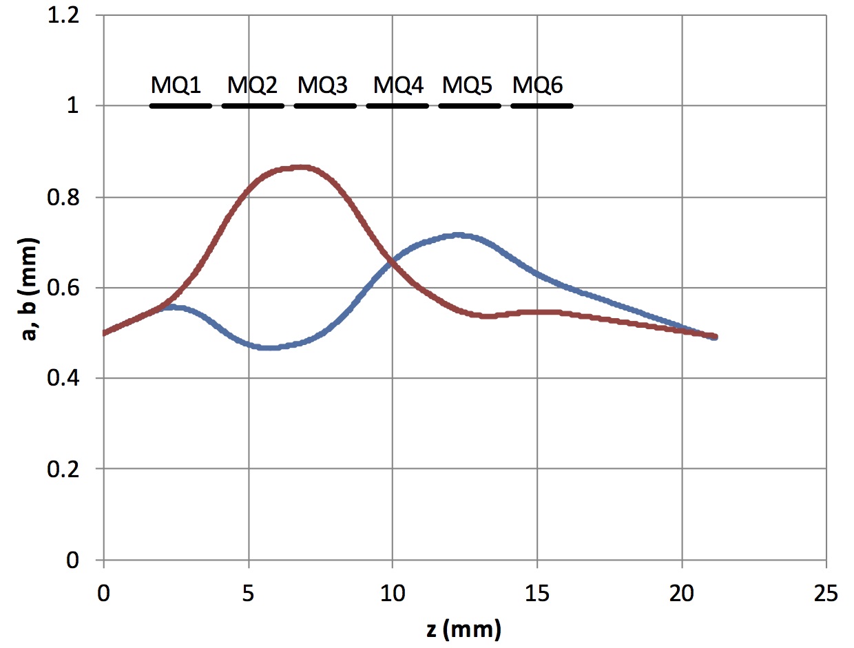
The input beam parameters are shown in Table 1, and the quadrupole voltages are all less than 600 Volts to be established in a bipolar manner. The solution is for an 8 keV Ar+ ion beam (I = 7 A, ). However, the quadrupole voltage solution is insensitive to the ion mass species and can transport a variety of ion species without extensive retuning.
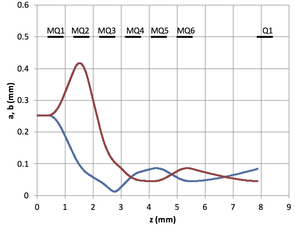
An envelope solution that establishes matched conditions at the beginning of an accelerator section is shown in Fig. 2.
| (mm) | 0.5 | (V) | 552 |
| (rad) | 0.028 | (V) | -500 |
| (mm) | 6.3e-4 | (V) | -512 |
| (keV) | 8.0 | (V) | 359 |
| mass (amu) | 40 | (V) | 352 |
| (V) | -136 |
III Quadrupole Fabrication and Experimental Setup
The principal components of the mechanical assembly are the electrodes which when electrically biased define the quadrupole field pattern, and the support frames which support the electrodes and maintain overall alignment. The electrodes are electroless nickel-coated on a monomer resin substrate pro . The substrates were manufactured with a rapid prototype, 3D-printing process, leading to the high precision (25 m) needed to maintain the electrode shapes and spacings for good alignment and field quality while maintaining low component cost. The electrode components are held in polyether ether ketone (PEEK) plastic support frames. Since this is a multiple beam structure, each polarity electrode for a quadrupole array is supported by connecting ribs to enable close spacing (Fig. 3).
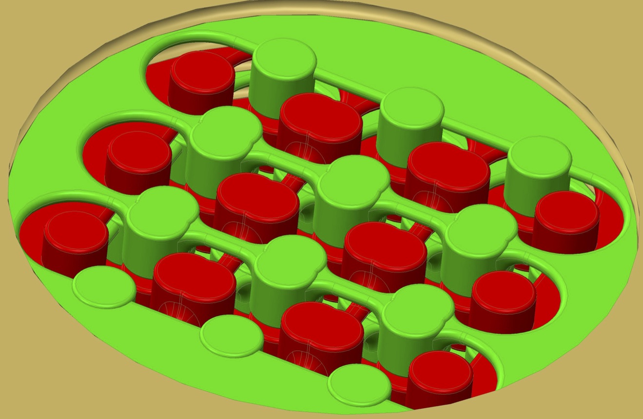
One set of electrodes overlays the opposing polarity electrodes and they fully overlap in forming a quadrupole of length 2 mm with gaps of 0.5 mm between successive quadrupoles. Electrical continuity to the electrodes is via soldered connections to a vapor deposited gold coating on the PEEK supports, which in turn is in contact with the nickel coated quadrupole electrodes. The nickel coating process slightly warped the quadrupole electrode parts. However, when held in place by the more rigid PEEK holders, the electrodes were restored to the desired coplanar orientation. A coordinate measuring survey of the assembly showed beam-center spacing (pitch between beams: 5.0 mm) errors and electrode diameter errors well within the 25 m tolerance specifications. The CAD model of the assembly is shown in Fig. 4, illustrating that a transverse array of quadrupoles is comprised of a pair of electrode parts where one part (green) will be biased to, e.g., for the horizontally oriented electrodes and the vertically oriented electrodes (red) are biased to . Thus, the voltages to establish a particular matching solution are common to all nine beams.
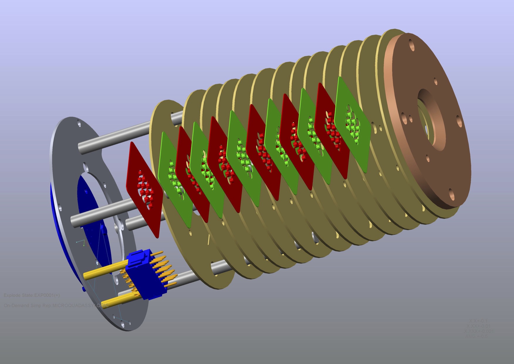
The assembled matching section is shown in Fig. 5. Note that there is considerable radial space available within this structure footprint to build a quadrupole array with many more beams, which would transmit a higher overall beam current, depending quadratically on the array size.
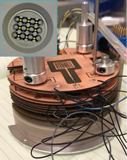
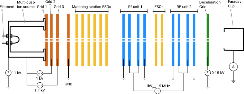
In previous workPersaud et al. (2016), we demonstrated acceleration of ion beams through four acceleration gaps and quadrupole focusing through a pair of electrostatic quadrupoles Persaud et al. (2017). In this work, we began by installing only the matching section downstream of the injector. The filament driven RF source with a array of extraction electrodes injected ions to the matching sectionJi et al. (2016). The exiting beam was diagnosed with an scintillator and image-intensified CCD camera. Following these observations, the RF accelerator section was added downstream of the matching section, with four acceleration gaps and two quadrupoles. The quadrupole and RF acceleration electrodes are fabricated from laser-cut copper clad PC-boards. The radius of the quadrupole and RF electrode apertures are 1 mm, half the matching section aperture. The exiting total ion beam current was measured in a Faraday cup, as shown in Fig. 6.
IV Results and Discussion
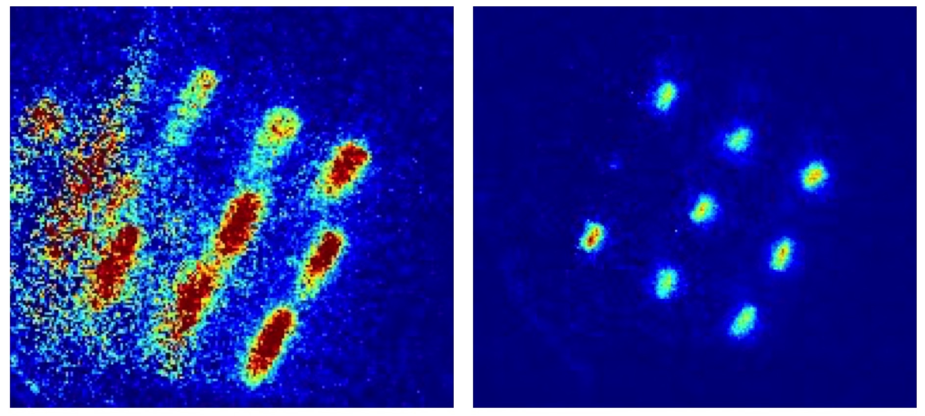
Each quadrupole was first energized separately and the expected ellipitical beam pattern was observed in accordance with the quadrupole polarity setting. Figure 7 shows an example for the first matching quadrupole energized. When all the quadrupoles are energized, the beams were more tightly-focused (the FWHM reduced by a factor 0.5).
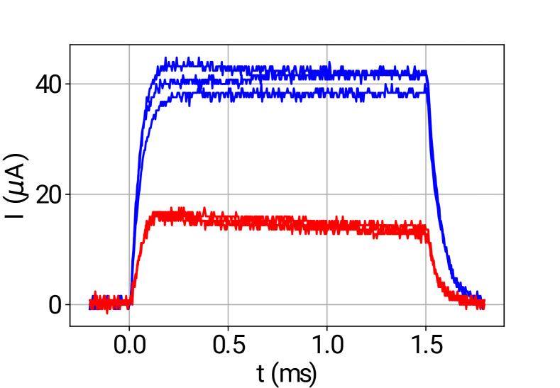
The ion source was pulsed for 1.5 ms, generating a nearly constant current during the pulse. Figure 8 shows that the transmitted beam current was approximately greater with the matching section energized.
We demonstrated the operation of the integrated assembly, including RF acceleration and quadrupole focusing in the acceleration section as shown in Fig. 6. The RF acceleration electrodes were driven from a common RF amplifier. Thus, the spacing between spacing between successive acceleration gaps was set to , as is common in many RF accelerators, where and , the RF wavelength. Thus particles near the peak of the acceleration waveform are subject to the same acceleration field at each gap.
The retarding potential of the decelerating grid was varied within the range , and the injected ion energy was keV. Since the RF frequency was 13.5 MHz, the relatively long beam pulses span many RF oscillations. Consequently, ions out of phase with the peak accelerating part of the RF waveform received less acceleration or were decelerated, and a continuum of ion energies is produced between and . Argon ion energies up to 13 keV were detected through the four acceleration gaps for 1.5 ms duration pulses. Extrapolating to many more acceleration gaps, the slower ions would be further out of phase and eventually lost, and the higher energy ions would be preferentially transported and accelerated.
Some voltage-breakdown in the matching section was observed. Contributing factors are secondary-electrons from ion lost to the electrodes. This will be remedied by tuning the envelope solution. Also, the matching section has a rather closed geometry, and we will add side-vents with higher pumping conductance to achieve a lower pressure within the matching section.
V Conclusion and Outlook
We have fabricated a compact, multiple-beam quadrupole matching system to transform the round beams exiting a multiple beam ion-source to the parameters required for high transmission of ions in an alternating gradient focusing system of an RF accelerator. The electrode structure substrates are 3D-printed monomer resins with nickel coating to define the quadrupole electrostatic fields, and parallel beams have a center-to-center spacing of 5 mm. The electrode lengths are 2 mm with a 0.5 mm gap between successive quadrupoles in the direction.
Scintillator measurements of the beam exiting the structure show the expected quadrupole focusing effect. When all the quadrupoles are energized, the focused intensity is increased and the beam diameter reduced. Faraday cup measurements also show that the transmitted current is more than doubled by the matching section. Experiments with the matching section coupled to the compact RF accelerator structure with four acceleration gaps including two focusing quadrupoles between acceleration stages showed ion acceleration from the additive acceleration from the four gaps.
The experience gained here point to improvements to the matching section design. Avoiding the warping caused by the nickel coating of the monomer electrode substrate may be accomplished by fabricating the part wholly out of metal in a 3D-printing process. Also, ports or vents on the side of the matching section will lower the local pressure in the path of the beam near the ion source, improving the voltage holdoff.
We are presently exploring methods for generating several kV of acceleration per acceleration gap with compact RF power sources. This is important to enable a compact accelerator ( m long) structure capable of generating 300 keV ions.
Higher average current and beam-power can be generated by introducing a bunching section Wangler (2008) after the ion source and matching section to more efficiently capture () the injected beam to the stable phase part of the RF acceleration waveform.
Scaling to many more parallel beams and higher current per beam will enable the development of this accelerator technology for high beam power applications. Neither require significant increases in component cost nor the development of advanced ion sources. For example, for the 5-mm pitch between focusing channels tested here, there is ample space to increase the number of parallel beams to on each 100-mm diameter wafer. Each beam could have a peak current of 120 A, consistent with established current densities from plasma based ion sources (ca. 15 mA/cm2). A total beam current of 9 mA can be produced in a compact structure, for a total beam power in the kilowatt range.
Acknowledgements.
We thank Takeshi Katayanagi for excellent technical support. We are grateful for insightful discussions with Andris Faltens and James Galvin. This work was supported by the US Department of Energy through the ARPA-E ALPHA program under contract DE-AC0205CH11231.References
- Maschke (1979a) A. Maschke, Technical report BNL-51022 (1979a), 10.2172/5914736.
- Maschke (1979b) A. Maschke, Technical report BNL-51029 (1979b), 10.2172/5914442.
- Urbanus et al. (1989) W. Urbanus, R. Wojke, J. Bannenberg, H. Klein, A. Schempp, R. Thomae, T. Weis, and P. V. Amersfoort, Nuclear Instruments and Methods in Physics Research Section B: Beam Interactions with Materials and Atoms 37-38, 508 (1989).
- Bangerter, Faltens, and Seidl (2013) R. O. Bangerter, A. Faltens, and P. A. Seidl, Reviews of Accelerator Science and Technology 06, 85 (2013).
- Persaud et al. (2016) A. Persaud, Q. Ji, E. Feinberg, P. A. Seidl, W. L. Waldron, T. Schenkel, A. Lal, K. B. Vinayakumar, S. Ardanuc, and D. A. Hammer, Review of Scientific Instruments 88, 063304 (2016).
- Persaud et al. (2017) A. Persaud, P. A. Seidl, Q. Ji, E. Feinberg, W. L. Waldron, T. Schenkel, S. Ardanuc, K. B. Vinayakumar, and A. Lal, Physics Procedia 90, 136 (2017).
- Hamm and Hamm (2012) R. W. Hamm and M. E. Hamm, eds., Industrial Accelerators and Their Applications (World Scientific, 2012).
- Sonato et al. (2017) P. Sonato, P. Agostinetti, T. Bolzonella, F. Cismondi, U. Fantz, A. Fassina, T. Franke, I. Furno, C. Hopf, I. Jenkins, E. Sartori, M. Tran, J. Varje, P. Vincenzi, and L. Zanotto, Nuclear Fusion 57, 056026 (2017).
- Reiser (1994) M. Reiser, “Theory and design of charged particle beams,” (John Wiley and Sons, Inc., New York, 1994) Chap. 4, pp. 234–240.
- (10) “MicroFine Green Resin, ProtoLabs service,” https://www.protolabs.com/media/638680/microfine-green-resin-fineline.pdf .
- Ji et al. (2016) Q. Ji, P. Seidl, W. Waldron, J. Takakuwa, A. Friedman, D. Grote, A. Persaud, J. Barnard, and T. Schenkel, Review of Scientific Instruments 87, 02B707 (2016).
- Wangler (2008) T. P. Wangler, RF Linear Accelerators (John Wiley and Sons, 2008) Chap. 4.