Self-error-corrected hyperparallel photonic quantum computation working with both the polarization and the spatial-mode degrees of freedom111Published in Opt. Express 26, 23333–23346 (2018).
Abstract
Usually, the hyperparallel quantum computation can speed up quantum computing, reduce the quantum resource consumed largely, resist to noise, and simplify the storage of quantum information. Here, we present the first scheme for the self-error-corrected hyperparallel photonic quantum computation working with both the polarization and the spatial-mode degrees of freedom of photon systems simultaneously. It can prevent bit-flip errors from happening with an imperfect nonlinear interaction in the nearly realistic condition. We give the way to design the universal hyperparallel photonic quantum controlled-NOT (CNOT) gate on a two-photon system, resorting to the nonlinear interaction between the circularly polarized photon and the electron spin in the quantum dot in a double-sided microcavity system, by taking the imperfect interaction in the nearly realistic condition into account. Its self-error-corrected pattern prevents the bit-flip errors from happening in the hyperparallel quantum CNOT gate, guarantees the robust fidelity, and relaxes the requirement for its experiment. Meanwhile, this scheme works in a failure-heralded way. Also, we generalize this approach to achieve the self-error-corrected hyperparallel quantum CNOTN gate working on a multiple-photon system. These good features make this scheme more useful in the photonic quantum computation and quantum communication in the future.
pacs:
03.67.Lx, 03.67.Pp, 03.65.Yz, 42.50.PqI Introduction
Quantum computation works as a pattern of parallel computing and it has a stronger capacity in information processing. It can speed up factorizing a large number Shor94 and searching data Grover97 ; Long01 . The ultimate aim of quantum computation is the realization of quantum computer and the key element of a quantum computer is the quantum controlled-NOT (CNOT) gate (or its equivalency, the quantum controlled-phase gate). Many physical architectures have been proposed to implement quantum computation, such as photons pgate1 ; pgate2 ; pgate3 ; pgate4 ; pgate5 ; pgate8 ; pgate9 ; pgate10 ; pgate11 ; pgate12 , atoms atgate1 ; atgate2 ; atgate3 ; atgate4 ; atgate6 ; atgate7 ; atgate8 ; atgate9 ; atgate10 , quantum dots qdgate1 ; qdgate3 ; qdgate5 ; qdgate6 ; qdgate7 ; qdgate4 , diamond nitrogen-vacancy defect centers nvgate1 ; nvgate2 , nuclear magnetic resonance nmrgate1 ; nmrgate2 ; nmrgate3 ; nmrgate4 ; nmrgate5 ; nmrgate6 ; nmrgate7 , and so on. Photon is an idea information carrier as it has a high transmission speed, a weak interaction with its environment, and a low cost for its preparation. Moreover, a photon system can have multiple degrees of freedom (DOFs), which can be used in various quantum information processing tasks pqip1 ; pqip2 ; pqip3 ; pqip4 ; pqip5 . A state of a photon system being simultaneously entangled in several DOFs is referred to as a hyperentanglement, and its generation has been extensively researched both theoretically and experimentally hbsg1 ; hbsg2 ; hbsg3 ; hbsg4 ; hbsg5 ; hbsg6 ; hbsg7 ; hbsg8 ; hbsg9 ; hbsg10 ; hbsg11 . The hyperentangled states of the photon systems can improve both the channel capacity and the security of quantum communication largely. The hyperparallel quantum computation is accomplished with the hyperentangled states of the photon systems. The hyperparallel quantum computation can achieve the full potential of the parallel computing in quantum computation, and it can speed up quantum computing, save quantum resource, resist to noise, and will be useful for easy storage in the following process.
The first protocol for the hyperparallel quantum CNOT gate was proposed by Ren et al. hyper1 in 2013. In their protocol, a deterministic hyper-CNOT gate is constructed and it operates in both the spatial-mode and the polarization DOFs for a photon pair simultaneously. Up to now, several hyperparallel quantum gate protocols have been proposed, including the hyperparallel CNOT gate on a two-photon system with two DOFs and the hyperparallel Toffoli gate on a three-photon system with two DOFs hyper2 ; hyper3 ; hyper4 ; hyper5 . A deterministic (hyperparallel) photonic quantum gate can be completed with nonlinearity interaction, which can be provided by a matter qubit such as an artificial atom trapped in a microcavity. The electron spin in a GaAs-based or InAs-based charged quantum dot (QD) trapped in a double-sided microcavity is an attractive matter qubit qdgate6 ; huqd1 . Utilizing the technique of spin echo, the electron spin coherence time of a charged QD can be maintained for more than 3 qdtime1 ; qdtime2 , and the electron spin relaxation time can be longer ( ) qdtime3 ; qdtime4 . The techniques of fast preparing the superposition states of an electron spin in a singly charged QD qdpre1 ; qdpre2 , fast manipulating the electron spin in a charged QD qdmani1 ; qdmani2 ; qdmani3 ; qdmani4 , and detecting the state of the electron spin in a charged QD qddete have been realized. Moreover, it is easy to embed a charged QD into a solid-state microcavity.
In the ideal case, the QD-microcavity system can provide a perfect nonlinear interaction which can be used to construct a unity-fidelity deterministic (hyperparallel) photonic quantum gate. When it turns into the realistic condition, the nonlinear interaction is not perfect, which will reduce the fidelity of the quantum gate. Fidelity, which is the description of the quality of the quantum gate, is defined as , where and are the realistic final state and the ideal final state, respectively. In the realistic condition, , which means there would be some errors in the final result of a quantum gate and leads to a non-unity fidelity. For a quantum CNOT gate, there would be bit-flip errors in the realistic condition and the fidelity would be non-unity. Specifically speaking, for a quantum CNOT gate, represents the initial state of the system, where the subscripts and respectively represent the control qubit and the target qubit, and the coefficients satisfy and . is the ideal final state after a quantum CNOT gate, which means the state of the target qubit is flipped when the control qubit is in the state , while it would not be changed when the control qubit is in the state . However, in the realistic condition, after the evolution of the system, the final state might be , which means there is a possibility that the state of the target qubit is not flipped when the control qubit is in the state and the state of the target qubit is flipped when the control qubit is in the state . The coefficients , , , and and the fidelity of the quantum CNOT gate are affected by the parameters of the photon and the QD-microcavity system. That is to say, in a quantum CNOT gate together with a hyperparallel quantum CNOT gate, bit-flip errors can happen in the realistic condition, which would be reflected by the non-unity fidelity. As the importance of improving the fidelity of a quantum gate, the research in quantum gates with a robust fidelity has attracted much attention and several interesting schemes of quantum gates for atom systems atgate7 ; atgate8 ; atgate9 and QD systems qdgate4 with robust fidelities have been proposed.
In this paper, we give an original approach to construct the universal self-error-corrected hyperparallel photonic quantum CNOT gate working on a two-photon system in both the polarization and the spatial-mode DOFs. In this gate, the state of one photon in the polarization and the spatial-mode DOFs controls the state of the other photon in the polarization and the spatial-mode DOFs simultaneously, which is equal to two identical quantum CNOT gates operating simultaneously on the systems in one DOF. It can speed up quantum computing, reduce the quantum resource consumed largely, resist to noise, and simplify the storage of quantum information in a practical application. More interestingly, it can prevent the bit-flip errors arising from the nearly realistic imperfect nonlinear interaction of the QD-microcavity system. Its self-error-corrected pattern prevents bit-flip errors from happening in the gate, guarantees its fidelity robust, and relaxes its requirement for the realistic parameters. This self-error-corrected hyperparallel photonic quantum CNOT gate also works in a failure-heralded way. Meanwhile, we generalize this approach of the self-error-corrected hyperparallel photonic quantum CNOT gate working on a two-photon system to achieve the self-error-corrected hyperparallel photonic quantum CNOTN gate working on a multiple-photon system, which also works in a failure-heralded way. These good features make this scheme more useful in the hyperparallel photonic quantum computation and the multiple-photon hyperentangled-state generation for quantum communication in the future.
II Nonlinear interaction between a circularly polarized photon and a QD in a double-sided microcavity
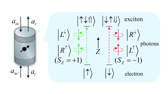
A singly charged electron In(Ga)As QD or a GaAs interface QD is set at the wave loop of a double-sided microcavity. The reflection coefficients of the bottom and the top distributed Bragg reflectors of the double-sided microcavity are the same. An excess electron is injected into the QD. After the optical excitation by a circularly polarized photon, an exciton consisting of two electrons bound to one heavy hole with negative charges is created. According to Pauli’s exclusion principle, the circularly polarized photon or () can only realize the transition from to , and the circularly polarized photon or () can only realize the transition from to , as shown in Fig. 1.
The dipole interaction process can be represented by Heisenberg equations of motion for the annihilation operator of the microcavity mode and the dipole operator of the exciton . The Heisenberg equations in the interaction picture and the input-output relationships are described as Walls94
| (1) |
Here is the coupling strength between the and the microcavity. , , and are frequencies of the photon, the microcavity, and transition, respectively. , , and represent dipole decay rate, the microcavity decay rate, and the microcavity leaky rate, respectively. and are noise operators. , , , and are the input and output field operators. In the weak excitation approximation (), after the nonlinear interaction between the circularly polarized photon and the QD-microcavity system, the reflection coefficient and the transmission coefficient can be described by qdgate6 ; anjunhong
| (2) |
If the circularly polarized photon interacts with a cold microcavity, that is , the reflection and the transmission coefficients can be written as
| (3) |
The evolution rules for the nonlinear interaction between the circularly polarized photon and the QD in a double-sided microcavity in the realistic condition can be described as qdgate6
| (4) |
III Self-error-corrected hyperparallel photonic quantum CNOT gate
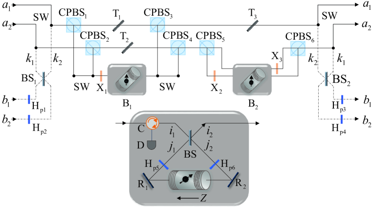
The hyperparallel photonic quantum CNOT gate working on a two-photon system in both the polarization and the spatial-mode DOFs, completes the task that when the polarization of photon (the control qubit) is in the state , a bit flip takes place on the state in the polarization DOF of photon (the target qubit), and simultaneously when the spatial mode of photon is in the state , a bit flip takes place on the state in the spatial-mode DOF of photon . The schematic diagram for our self-error-corrected hyperparallel photonic quantum CNOT gate is shown in Fig. 2. The QD-microcavity system is set in a basic block and the circularly polarized photon interacts with the QD-microcavity system through the basic block. In this way, the hyperparallel photonic quantum CNOT gate is constructed with a self-error-corrected pattern and works in a failure-heralded way.
The schematic diagram for the basic block is shown in the inset of Fig. 2. The electron spin in the QD in the microcavity is initially prepared in the state and a right-circularly polarized photon is injected into the basic block from the input path. After the photon passing through BS and H, it interacts with the QD-microcavity system. The rules of the nonlinear interaction between the photon and the QD-microcavity system in the realistic condition is governed by Eq. (4). And at last the photon passes through H and BS again. The final state of the system consisting of the photon and the electron spin in the QD becomes
| (5) |
Similarly, when the electron spin in the QD in the microcavity is initially prepared in the state , after a right-circularly polarized photon passing through the basic block from the input path, the final state of the system becomes
| (6) |
and in Eqs. (5) and (6) are the reflection coefficient and the transmission coefficient for the basic block. Equations. (5) and (6) describe the rules of the interaction between the photon and the basic block. If the photon is reflected from the basic block with the probability of , the polarization of the photon and the state of the electron spin in the QD would not be changed. The reflected photon would be detected by the single-photon detector and the following process would be terminated. If the photon is transmitted from the basic block with the probability of , the polarization of the photon would be changed and the state of the electron spin in the QD would be changed as . The transmitted photon will be used in the following process and the system consisting of the photon and the electron spin in the QD has an integrated coefficient , which can guarantee the fidelity unity in the nearly realistic condition.
Based on the rules of the interaction between a right-circularly polarized photon and a basic block, a self-error-corrected hyperparallel photonic quantum CNOT gate working in a failure-heralded way can be constructed. The detail principle can be described as follows in step by step.
Initially, the two electron spins in QD1 and QD2 are prepared in the states and , and the two photons and are in the states and , respectively. Here, , , , and .
First, photon is injected into the circuit from the input path . After photon passes through CPBS1 and CPBS2, in both of the two spatial modes and , the wave packet in the left-circular polarization will pass through X1 and the first basic block B1, and the wave packet in the right-circular polarization will pass through T1 and T2. If there is a click of the single-photon detector in B1, the process of the self-error-corrected hyperparallel photonic quantum CNOT gate fails and it is terminated. If the single-photon detector in B1 does not click, the whole process will continue. The wave packet in the left-circular polarization and the wave packet in the right-circular polarization would reunion after passing through CPBS3,4. In this time, the state of the hybrid system consisting of two photons and and two electron spins in QD1 and QD2 is changed from to . Here
| (7) |
Subsequently, for the wave packet of photon in the spatial mode , it transmits through T3. For the wave packet of photon in the spatial mode , after it passes through CPBS5, the wave packet in the left-circular polarization transmits through X2 and the second basic block B2 in sequence, and the wave packet in the right-circular polarization transmits through the second basic block B2 and X3 in sequence. Similarly, if there is a click of the single-photon detector in B2, the process of the self-error-corrected hyperparallel photonic quantum CNOT gate fails and it is terminated. If there is no click of the single-photon detector in B2, the two wave packets of different polarizations in the spatial mode reunion at CPBS6, and the photon comes out of the quantum circuit from path . And then Hadamard operations are respectively performed on the electron spins in QD1 and QD2. The state of the hybrid system is changed into
| (8) |
Second, photon is injected into the circuit from the input path . After photon passes through Hp1,2 and BS1, the state of the hybrid system becomes
| (9) |
Here, . Subsequently, photon passes through the circuit consisting of the optical elements and two basic blocks. Similarly, if there is a click of the single-photon detector in B1 or B2, the process of the self-error-corrected hyperparallel photonic quantum CNOT gate fails and it is terminated. If there is no click, the whole process will continue. The polarization Hadamard and spatial-mode Hadamard operations are performed again on photon by HP3,4 and BS2, respectively. Hadamard operations are performed either on the two electron spins in QD1 and QD2 again. In this time, the state of the system consisting of two photons and and two electron spins in QD1 and QD2 is changed into
At last, the electron spins in QD1 and QD2 are measured in the orthogonal basis . If the electron spin in QD1 is in the state , an additional phase-flip operation is performed on photon , and if the electron spin in QD2 is in the state , an additional phase-flip operation is performed on photon . Conditioned on the results of the measurement on the QD1 and QD2, the two-photon system, up to a single-photon rotation, is collapsed into the desired state with a success probability as follows
| (11) |
From Eq. (11), one can see that there is a bit flip of the state on the polarization DOF for photon when the polarization of photon is in the state , and there is a bit flip of the state on the spatial-mode DOF for photon when the spatial mode of photon is in the state . Meanwhile, from Eq. (11), one can see that in the nearly realistic condition with imperfect nonlinear interaction, bit-flip errors do not happen in our hyperparallel photonic quantum CNOT gate, which means it works in the self-error-corrected pattern. Furthermore, from Eq. (III), one can see that is an integrated coefficient for the state of the two-photon system and the two electron spins in the QDs. Transmission coefficient for the basic block is the function of transmission coefficient and reflection coefficient which are affected by the experimental parameters , , , , , , and . That is to say, these experimental parameters would not affect the fidelity of the hyperparallel photonic quantum CNOT gate, which relaxes the requirement for experiment. Overall, the schematic diagram shown in Fig. 2 completes a self-error-corrected hyperparallel photonic quantum CNOT gate in the nearly realistic condition, which eliminates bit-flip errors, guarantees a robust fidelity, and relaxes the requirement for experiment, and its failure is heralded by the single-photon detectors.
IV Self-error-corrected hyperparallel photonic quantum CNOTN gate
The previous approach completes the self-error-corrected hyperparallel quantum CNOT gate working on a two-photon system, which can be generalized to achieve the self-error-corrected hyperparallel quantum CNOTN gate working on a multiple-photon system. The self-error-corrected hyperparallel photonic quantum CNOTN gate working on a multiple-photon system is completed with two basic blocks consisting of two QD-microcavity systems as auxiliaries, which is the same as the self-error-corrected hyperparallel quantum CNOT gate working on a two-photon system. Initially, the two electron spins in the two QDs are prepared in the states and . The control photon is in the state with and . The target photons are in the states with and .
The schematic diagram shown in Fig. 2 can also be used to achieve the self-error-corrected hyperparallel photonic quantum CNOTN gate. First, the control photon is injected into the circuit from input path . During photon passing through the circuit, if there is a click of the single-photon detector in the basic block B1 or B2, the process of self-error-corrected hyperparallel photonic quantum CNOTN gate fails and it is terminated. If there is no click of the single-photon detector in B1 nor B2, with Hadamard operations respectively performed on the electron spins in QD1 and QD2, the state of the hybrid system is changed into
| (12) |
Second, the first target photon is injected into the circuit from the input path . Similarly, during photon passing through the circuit, if there is a click of the single-photon detector in the basic block B1 or B2 the process of self-error-corrected hyperparallel photonic quantum CNOTN gate fails and it is terminated. If there is no click of the single-photon detector in B1 nor B2, the state of the hybrid system evolves into
| (13) |
Subsequently, the target photon from to is injected into the circuit from the input path one by one. The process is similar to the case that the click of the single-photon detector in B1 or B2 heralded the failure of the self-error-corrected hyperparallel photonic quantum CNOTN gate. If there is no click of the single-photon detector in B1 nor B2, after the last target photon exits from the output path , the state of the hybrid system is changed into
| (14) |
At last, Hadamard operations are performed on both the two electron spins in QD1 and QD2, and they are measured in the orthogonal basis . If the electron spin in QD1 and the electron spin in QD2 are respectively in the state and , the control photon and the target photons are in the state
| (15) |
If the electron spins in QD1 and QD2 are respectively in the state and , with respective additional phase-flip operations and on photon , the photon system consisting of one control photon and target photons is also projected into the state as shown in Eq. (15), which shows that there is a bit flip of the state on the polarization DOF for each target photon when the polarization of the control photon is in the state , and there is a bit flip of the state on the spatial-mode DOF for each target photon when the spatial mode of the control photon is in the state . Meanwhile, Eq. (15) is obtained under the consideration of nearly realistic condition, in which there are no terms show the happening of bit-flip errors. Furthermore, from Eq. (14), one can see is an integrated coefficient for the state of the system, so the fidelity of hyperparallel photonic quantum CNOTN gate is robust to the realistic experimental parameters, which relaxes the requirement for experiment. Overall, the approach of self-error-corrected hyperparallel quantum CNOT gate for a two-photon system is successively generalized to achieve the self-error-corrected hyperparallel quantum CNOTN gate for a multiple-photon system, which eliminates bit-flip errors, guarantees a robust fidelity, and relaxes the requirement for experiment, and its failure is heralded by single-photon detectors.
V Discussion and summary
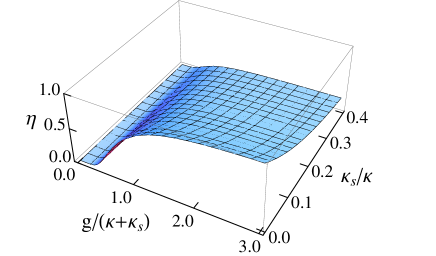
The efficiency is defined as the ratio of the number of the output photons to the input photons. The efficiency of the self-error-corrected hyperparallel photonic quantum CNOT gate is described as
| (16) |
which varies with the parameter and as shown in Fig. 3. The non-unity efficiency of our proposal originates from photon loss. For example, there is a probability that a part of the photons are detected by single-photon detectors in the two basic blocks and these photons can also lose when passing through partially transmitted mirrors. For a practical scattering condition with and , the efficiency of our self-error-corrected hyperparallel photonic quantum CNOT gate can reach . With the same experimental parameters, the efficiencies of our self-error-corrected hyperparallel photonic quantum CNOT2 gate and CNOT3 gate can reach and , respectively.
The fidelities of our self-error-corrected hyperparallel photonic quantum CNOT gate and CNOTN gate are robust to the experimental parameters , , , , , , and , which relaxes the requirement for experiment. Exciton dephasing is a slight factor which would have a negative effect on the fidelity qdtime5 . Taking the microcavity photon lifetime and the electron spin coherence time qdtime6 into account, the fidelity of every QD-microcavity system would be affected by an amount of . Meanwhile, the imperfect mixing of heavy-light hole would lead to an imperfect optical selection which could affect the fidelity a little as well qd1 . This imperfect mixing can be suppressed by engineering the shape and the size of QDs or by choosing the types of QDs.
The accomplishment of our self-error-corrected hyperparallel photonic quantum CNOT gate and CNOTN gate requires the technique of the measurement on the state of the electron spin in the QD in the orthogonal basis , which can be realized by measuring the helicity of the transmitted or reflected photon. Meanwhile, two transitions and couple to two microcavity modes with right- and left-circular polarization. So the microcavity for supporting two circularly polarized modes with the same frequency is required. This requirement can be satisfied modes1 ; modes2 ; modes3 ; modes4 . For example, in 2012, Luxmoore et al. precisely tuned the energy split between the two circularly polarized microcavity modes to just 0.15 modes1 . Also, the accomplishment of our scheme needs optical switches, which can couple different photons in and out the circuit of photonic quantum gate and couple different spatial modes of one photon in and out the circuit of the basic block. The performance of optical switch such as loss, delays, and the destruction on the photons, would affect the performance of our scheme. Fortunately, the suitable ultrafast optical switching device, that enables us to route single photons for quantum information processing, has been demonstrated. These switches exhibit a minimal loss, high speed performance, and a high contrast without disturbing the quantum state of photons that pass through them os1 ; os2 ; os3 . For instance, an ultrafast switch has been experimentally demonstrated and it completes the switch operation in 10 os1 , which is much shorter than the electron spin coherence time of a charged QD (3) qdtime1 ; qdtime2 . In our scheme, the failure-heralded character relies on the clicks of single-photon detectors in basic blocks. When there is a click of either single-photon detector, the process of self-error-corrected hyperparallel photonic CNOT gate and CNOTN gate fails and it will be terminated. If the single-photon detector is perfect enough, no click of the single-photon detector marks the success of the scheme.
For establishing scalable quantum computation, multiqubit gates are useful. As well known, they can be constructed by two-qubit gates and single-qubit gates BBC95 . The direct realization of a multiqubit gate with one control qubit and multiple target qubits is essential and more efficient, and this topic has attracted much attention atgate6 ; hyper5 ; nqubit1 ; nqubit2 ; nqubit3 ; nqubit4 . Fortunately, through directly generalizing our approach of self-error-corrected hyperparallel photonic quantum CNOT gate working on a two-photon system, the self-error-corrected hyperparallel photonic quantum CNOTN gate working on a multiple-photon system is achieved, in which one photon in the polarization and the spatial-mode DOFs respectively controls all of the target photons in the polarization and the spatial-mode DOFs. Our self-error-corrected hyperparallel photonic quantum CNOTN gate is directly achieved rather than constructed by universal quantum gates, which has a potential in performing hyperentanglement preparation SB01 , error corrections TCT14 , and quantum algorithms BR01 ; LFL15 .
In summary, we have presented the first scheme for designing the self-error-corrected hyperparallel photonic quantum CNOT gate, which relaxes the problem of the bit-flip errors happening in the quantum gate in the nearly realistic condition. The self-error-corrected pattern of our hyperparallel photonic quantum CNOT gate decreases the bit-flip errors, guarantees the robust fidelity, and relaxes the requirement of its experiment. Meanwhile, our self-error-corrected hyperparallel photonic quantum CNOT gate works in a failure-heralded way, as the clicks of single-photon detectors can mark the failure of the self-error-corrected hyperparallel photonic quantum CONT gate. Moreover, it can be generalized to the self-error-corrected hyperparallel photonic quantum CONTN gate, which also works in the failure-heralded way. These features make our scheme more useful in quantum computation and the multi-photon hyperentangled-state generation in quantum communication in the future.
ACKNOWLEDGEMENTS
This work is supported by the National Natural Science Foundation of China under Grants No. 11474026, No. 11674033, and No. 11505007, and the Fundamental Research Funds for the Central Universities under Grant No. 2015KJJCA01.
References
- (1) P. W. Shor, “Algorithms for quantum computation: discrete logarithms and factoring,” in Proceedings of the 35th Annual Symposium on Foundations of Computer Science, S. Goldwasser, ed. (IEEE Computer Society Press, 1994), pp. 124–134.
- (2) L. K. Grover, “Quantum mechanics helps in searching for a needle in a haystack,” Phys. Rev. Lett. 79, 325–328 (1997).
- (3) G. L. Long, “Grover algorithm with zero theoretical failure rate,” Phys. Rev. A 64, 022307 (2001).
- (4) E. Knill, R. Laflamme, and G. J. Milburn, “A scheme for efficient quantum computation with linear optics,” Naure 409, 46–52 (2001).
- (5) M. A. Nielsen, “Optical quantum computation using cluster states,” Phys. Rev. Lett. 93, 040503 (2004).
- (6) Y. X. Gong, G. C. Guo, and T. C. Ralph, “Methods for a linear optical quantum Fredkin gate,” Phys. Rev. A 78, 012305 (2008).
- (7) J. L. O’ Brien, G. J. Pryde, A. G. White, T. C. Ralph, and D. Branning, “Demonstration of an all-optical quantum controlled-NOT gate,” Naure 426, 264–267 (2003).
- (8) S. Gasparoni, J. W. Pan, P. Walther, T. Rudolph, and A. Zeilinger, “Realization of a photonic controlled-NOT gate sufficient for quantum computation,” Phys. Rev. Lett. 93, 020504 (2004).
- (9) K. Nemoto and W. J. Munro, “Nearly deterministic linear optical controlled-NOT gate,” Phys. Rev. Lett. 93, 250502 (2004).
- (10) X. Q. Li, Y. W. Wu, D. Steel, D. Gammon, T. H. Stievater, D. S. Katzer, D. Park, C. Piermarocchi, and L. J. Sham, “An all-optical quantum gate in a semiconductor quantum dot,” Science 301, 809–811 (2003).
- (11) H. R. Wei and F. G. Deng, “Scalable photonic quantum computing assisted by quantum-dot spin in double-sided optical microcavity,” Opt. Express 21, 17671–17685 (2013).
- (12) C. Wang, Y. Zhang, R. Z. Jiao, and G. S. Jin, “Universal quantum controlled phase gate on photonic qubits based on nitrogen vacancy centers and microcavity resonators,” Opt. Express 21, 19252–19260 (2013).
- (13) Y. H. Kang, Y. Xia, and P. M. Lu, “Two-photon phase gate with linear optical elements and atom-cavity system,” Quantum Inf. Process. 15, 4521–4535 (2016).
- (14) D. Jaksch, H. J. Briegel, J. I. Cirac, C. W. Gardiner, and P. Zoller, “Entanglement of atoms via cold controlled collisions,” Phys. Rev. Lett. 82, 1975–1978 (1999).
- (15) D. Jaksch, J. I. Cirac, P. Zoller, S. L. Rolston, R. Côté, and M. D. Lukin, “Fast quantum gates for neutral atoms,” Phys. Rev. Lett. 85, 2208–2211 (2000).
- (16) L. Isenhower, E. Urban, X. L. Zhang, A. T. Gill, T. Henage, T. A. Johnson, T. G. Walker, and M. Saffman, “Demonstration of a neutral atom controlled-NOT quantum gate,” Phys. Rev. Lett. 104, 010503 (2010).
- (17) A. S. Sørensen and K. Mølmer, “Measurement induced entanglement and quantum computation with atoms in optical cavities,” Phys. Rev. Lett. 91, 097905 (2003).
- (18) H. F. Wang, A. D. Zhu, and S. Zhang, “One-step implementation of a multiqubit phase gate with one control qubit and multiple target qubits in coupled cavities,” Opt. Lett. 39, 1489–1492 (2014).
- (19) Y. Li, L. Aolita, D. E. Chang, and L. C. Kwek, “Robust-fidelity atom-photon entangling gates in the weak-coupling regime,” Phys. Rev. Lett. 109, 160504 (2012).
- (20) J. Borregaard, P. Kómár, E. M. Kessler, A. S. Sørensen, and M. D. Lukin, “Heralded quantum gates with integrated error detection in optical cavities,” Phys. Rev. Lett. 114, 110502 (2015).
- (21) W. Qin, X. Wang, A. Miranowicz, Z. Zhong, and F. Nori, “Heralded quantum controlled-phase gates with dissipative dynamics in macroscopically distant resonators,” Phys. Rev. A 96, 012315 (2017).
- (22) J. Song, Y. Xia, and H. S. Song, “Quantum gate operations using atomic qubits through cavity input-output process,” Europhys. Lett. 87, 50005 (2009).
- (23) D. Loss and D. P. DiVincenzo, “Quantum computation with quantum dots,” Phys. Rev. A 57, 120–126 (1998).
- (24) A. Imamoglu, D. D. Awschalom, G. Burkard, D. P. DiVincenzo, D. Loss, M. Sherwin, and A. Small, “Quantum information processing using quantum dot spins and cavity QED,” Phys. Rev. Lett. 83, 4204–4207 (1999).
- (25) C. Y. Hu, W. J. Munro, and J. G. Rarity, “Deterministic photon entangler using a charged quantum dot inside a microcavity,” Phys. Rev. B 78, 125318 (2008).
- (26) C. Y. Hu, W. J. Munro, J. L. O’Brien, and J. G. Rarity, “Proposed entanglement beam splitter using a quantum-dot spin in a double-sided optical microcavity,” Phys. Rev. B 80, 205326 (2009).
- (27) H. R. Wei and F. G, Deng, “Universal quantum gates on electron-spin qubits with quantum dots inside single-side optical microcavities,” Opt. Express 22, 593–607 (2014).
- (28) T. Li and F. G. Deng, “Error-rejecting quantum computing with solid-state spins assisted by low-Q optical microcavities,” Phys. Rev. A 94, 062310 (2016).
- (29) T. van der Sar, Z. H. Wang, M. S. Blok, H. Bernien, T. H. Taminiau, D. M. Toyli, D. A. Lidar, D. D. Awschalom, R. Hanson, and V. V. Dobrovitski, “Decoherence-protected quantum gates for a hybrid solid-state spin register,” Nature 484, 82–86 (2012).
- (30) H. R. Wei and F. G. Deng, “Compact quantum gates on electron-spin qubits assisted by diamond nitrogen-vacancy centers inside cavities,” Phys. Rev. A 88, 042323 (2013).
- (31) N. A. Gershenfeld and I. L. Chuang, “Bulk spin-resonance quantum computation,” Science 275, 350–356 (1997).
- (32) D. G. Cory, A. F. Fahmy, and T. F. Havel, “Ensemble quantum computing by NMR-spectroscopy,” Proc. Natl. Acad. Sci. United States Am. 94, 1634–1639 (1997).
- (33) I. L. Chuang, N. Gershenfeld, M. G. Kubinec, and D. W. Leung, “Bulk quantum computation with nuclear magnetic resonance: theory and experiment,” Proceeding Royal Soc. A 454, 447–467 (1998).
- (34) R. Schack and C. M. Caves, “Classical model for bulk-ensemble NMR quantum computation,” Phys. Rev. A 60, 4354–4362 (1999).
- (35) J. A. Jones, V. Vedral, A. Ekert, and G. Castagnoli, “Geometric quantum computation using nuclear magnetic resonance,” Nature 403, 869–871 (2000).
- (36) G. R. Feng, G. F. Xu, and G. L. Long, “Experimental realization of nonadiabatic holonomic quantum computation,” Phys. Rev. Lett. 110, 190501 (2013).
- (37) Y. Long, G. R. Feng, Y. C. Tang, W. Qin, and G. L. Long, “NMR realization of adiabatic quantum algorithms for the modified simon problem,” Phys. Rev. A 88, 012306 (2013).
- (38) L. Marrucci, C. Manzo, and D. Paparo, “Optical spin-to-orbital angular momentum conversion in inhomogeneous anisotropic media,” Phys. Rev. Lett. 96, 163905 (2006).
- (39) E. Nagali, F. Sciarrino, F. De Martini, L. Marrucci, B. Piccirillo, E. Karimi, and E. Santamato, “Quantum information transfer from spin to orbital angular momentum of photons,” Phys. Rev. Lett. 103, 013601 (2009).
- (40) A. R. C. Pinheiro, C. E. R. Souza, D. P. Caetano, J. A. O. Huguenin, A. G. M. Schmidt, and A. Z. Khoury, “Vector vortex implementation of a quantum game,” J. Opt. Soc. Am. B 30, 3210–3214 (2013).
- (41) G. Milione, T. A. Nguyen, J. Leach, D. A. Nolan, and R. Alfano, “Using the nonseparability of vector beams to encode information for optical communication,” Opt. Lett. 40, 4887–4890 (2015).
- (42) W. F. Balthazar, C. E. R. Souza, D. P. Caetano, E. F. Galvão, J. A. O. Huguenin, and A. Z. Khoury, “Tripartite nonseparability in classical optics,” Opt. Lett. 41, 5797–5800 (2016).
- (43) G. Vallone, R. Ceccarelli, F. De Martini, and P. Mataloni, “Hyperentanglement of two photons in three degrees of freedom,” Phys. Rev. A 79, 030301(R) (2009).
- (44) D. Bhatti, J. von Zanthier, and G. S. Agarwal, “Entanglement of polarization and orbital angular momentum,” Phys. Rev. A 91, 062303 (2015).
- (45) J. T. Barreiro, N. K. Langford, N. A. Peters, and P. G. Kwiat, “Generation of hyperentangled photon pairs,” Phys. Rev. Lett. 95, 260501 (2005).
- (46) C. Cinelli, M. Barbieri, F. De Martini, and P. Mataloni, “Realization of hyperentangled two-photon states,” Laser Phys. 15, 124–128 (2005).
- (47) M. Barbieri, C. Cinelli, F. De Martini, and P. Mataloni, “Generation of (22) and (44) two-photon states with tunable degree of entanglement and mixedness,” Fortschritte der Physik 52, 1102–1109 (2004).
- (48) M. Barbieri, C. Cinelli, P. Mataloni, and F. De Martini, “Polarization-momentum hyperentangled states: Realization and characterization,” Phys. Rev. A 72, 052110 (2005).
- (49) A. Rossi, G. Vallone, A. Chiuri, F. De Martini, and P. Mataloni, “Multipath entanglement of two photons,” Phys. Rev. Lett. 102, 153902 (2009).
- (50) F. G. Deng, B. C. Ren, and X. H. Li, “Quantum hyperentanglement and its applications in quantum information processing,” Sci. Bull. 62, 46–68 (2017)
- (51) Y. Q. He, D. Ding, P. Tao, F. L. Yan, and T. Gao, “Generation of four-photon hyperentangled state using spontaneous parametric down-conversion source with the second-order term,” Acta Phys. Sin. 67, 060302 (2018).
- (52) B. Coutinho dos Santos, K. Dechoum, and A. Z. Khoury, “Continuous-variable hyperentanglement in a parametric oscillator with orbital angular momentum,” Phys. Rev. Lett. 103, 230503 (2009).
- (53) K. Liu, J. Guo, C. X. Cai, S. F. Guo, and J. R. Gao, “Experimental Generation of Continuous-Variable Hyperentanglement in an Optical Parametric Oscillator,” Phys. Rev. Lett. 113, 170501 (2014).
- (54) B. C. Ren, H. R. Wei, and F. G. Deng, “Deterministic photonic spatial-polarization hyper-controlled-not gate assisted by a quantum dot inside a one-side optical microcavity,” Laser Phys. Lett. 10, 095202 (2013).
- (55) B. C. Ren and F. G. Deng, “Hyper-parallel photonic quantum computation with coupled quantum dots,” Sci. Rep. 4, 4623 (2014).
- (56) T. J. Wang, Y. Zhang, and C. Wang, “Universal hybrid hyper-controlled quantum gates assisted by quantum dots in optical double-sided microcavities,” Laser Phys. Lett. 11, 025203 (2014).
- (57) B. C. Ren, G. Y. Wang, and F. G. Deng, “Universal hyperparallel hybrid photonic quantum gates with dipole-induced transparency in the weak-coupling regime,” Phys. Rev. A 91, 032328 (2015).
- (58) T. Li and G. L. Long, “Hyperparallel optical quantum computation assisted by atomic ensembles embedded in double-sided optical cavities,” Phys. Rev. A 94, 022343 (2016).
- (59) C. Y. Hu, A. Young, J. L. O’Brien, W. J. Munro, and J. G. Rarity, “Giant optical Faraday rotation induced by a single-electron spin in a quantum dot: applications to entangling remote spins via a single photon,” Phys. Rev. B 78, 085307 (2008).
- (60) J. R. Petta, A. C. Johnson, J. M. Taylor, E. A. Laird, A. Yacoby, M. D. Lukin, C. M. Marcus, M. P. Hanson, and A. C. Gossard, “Coherent manipulation of coupled electron spins in semiconductor quantum dots,” Science 309, 2180–2184 (2005).
- (61) A. Greilich, D. R. Yakovlev, A. Shabaev, A. L. Efros, I. A. Yugova, R. Oulton, V. Stavarache, D. Reuter, A. Wieck, and M. Bayer, “Mode locking of electron spin coherences in singly charged quantum dots,” Science 313, 341–345 (2006).
- (62) J. M. Elzerman, R. Hanson, L. H. Willems van Beveren, B. Witkamp, L. M. K. Vandersypen, and L. P. Kouwenhoven, “Single-shot read-out of an individual electron spin in a quantum dot,” Nature 430, 431–435 (2004).
- (63) M. Kroutvar, Y. Ducommun, D. Heiss, M. Bichler, D. Schuh, G. Abstreiter, and J. J. Finley, “Optically programmable electron spin memory using semiconductor quantum dots,” Nature 432, 81–84 (2004).
- (64) M. Atatüre, J. Dreiser, A. Badolato, A. Högele, K. Karrai, and A. Imamoglu, “Quantum-dot spin-state preparation with near-unity fidelity,” Science 312, 551–553 (2006).
- (65) M. Atatüre, J. Dreiser, A. Badolato, and A. Imamoglu, “Observation of faraday rotation from a single confined spin,” Nat. Phys. 3, 101–106 (2007).
- (66) J. Berezovsky, M. H. Mikkelsen, N. G. Stoltz, L. A. Coldren, and D. D. Awschalom, “Picosecond coherent optical manipulation of a single electron spin in a quantum dot,” Science 320, 349–352 (2008).
- (67) D. Press, T. D. Ladd, B. Y. Zhang, and Y. Yamamoto, “Complete quantum control of a single quantum dot spin using ultrafast optical pulses,” Nature 456, 218–221 (2008).
- (68) J. A. Gupta, R. Knobel, N. Samarth, and D. D. Awschalom, “Ultrafast manipulation of electron spin coherence,” Science 292, 2458–2461 (2001).
- (69) P. C. Chen, C. Piermarocchi, L. J. Sham, D. Gammon, and D. G. Steel, “Theory of quantum optical control of a single spin in a quantum dot,” Phys. Rev. B 69, 075320 (2004).
- (70) R. Hanson, L. H. Willems van Beveren, I. T. Vink, J. M. Elzerman, W. J. M. Naber, F. H. L. Koppens, L. P. Kouwenhoven, and L. M. K. Vandersypen, “Single-shot readout of electron spin states in a quantum dot using spin-dependent tunnel rates,” Phys. Rev. Lett. 94, 196802 (2005).
- (71) D. F. Walls and G. J. Milburn, Quantum Optics, (Springer-Verlag, 1994).
- (72) J. H. An, M. Feng, and C. H. Oh, “Quantum-information processing with a single photon by an input-output process with respect to low-Q cavities,” Phys. Rev. A 79, 032303 (2009).
- (73) C. Y. Hu and J. G. Rarity, “Loss-resistant state teleportation and entanglement swapping using a quantum-dot spin in an optical microcavity,” Phys. Rev. B 83, 115303 (2011).
- (74) D. Press, K. De Greve, P. L. McMahon, T. D. Ladd, B. Friess, C. Schneider, M. Kamp, S. Höfling, A. Forchel, and Y. Yamamoto, “Ultrafast optical spin echo in a single quantum dot,” Nat. Photonics 4, 367–370 (2010).
- (75) G. Bester, S. Nair, and A. Zunger, “Pseudopotential calculation of the excitonic fine structure of million-atom self-assembled quantum dots,” Phys. Rev. B 67, 161306 (2003).
- (76) I. J. Luxmoore, E. D. Ahmadi, B. J. Luxmoore, N. A.Wasley, A. I. Tartakovskii, M. Hugues, M. S. Skolnick, and A. M. Fox, “Restoring mode degeneracy in H1 photonic crystal cavities by uniaxial strain tuning,” 100, 121116 (2012).
- (77) C. Bonato, E. van Nieuwenburg, J. Gudat, S. Thon, H. Kim, M. P. van Exter, and D. Bouwmeester, “Strain tuning of quantum dot optical transitions via laser-induced surface defects,” Phys. Rev. B 84, 075306 (2011).
- (78) K. Hennessy, C. Högerle, E. Hu, A. Badolato, and A. Imamoğlu, “Tuning photonic nanocavities by atomic force microscope nano-oxidation,” Appl. Phys. Lett. 89, 041118 (2006).
- (79) Y. Eto, A. Noguchi, P. Zhang, M. Ueda, and M. Kozuma, “Projective measurement of a single nuclear spin qubit by using two-mode cavity QED,” Phys. Rev. Lett. 106, 160501 (2011).
- (80) M. Hall, J. Altepeter, and P. Kumar, “Ultrafast switching of photonic entanglement,” Phys. Rev. Lett. 106, 053901 (2011).
- (81) M. Hall, J. Altepeter, and P. Kumar, “All-optical switching of photonic entanglement,” New J. Phys. 13, 105004 (2011).
- (82) T. M. Rambo, J. B. Altepeter, and P. Kumar, “Functional quantum computing: An optical approach,” Phys. Rev. A 93, 052321 (2016).
- (83) A. Barenco, C. H. Bennett, R. Cleve, D. P. DiVincenzo, N. Margolus, P. Shor, T. Sleator, J. A. Smolin, and H. Weinfurter, “Elementary gates for quantum computation,” Phys. Rev. A 52, 3457 (1995). %ֱ ӹ
- (84) G. W. Lin, X. B. Zou, X. M. Lin, and G. C. Guo, “Robust and fast geometric quantum computation with multiqubit gates in cavity QED,” Phys. Rev. A 79, 064303 (2009).
- (85) C. P. Yang, S. B. Zheng, and F. Nori, “Multiqubit tunable phase gate of one qubit simultaneously controlling n qubits in a cavity,” Phys. Rev. A 82, 062326 (2010).
- (86) C. P. Yang, Q. P. Su, F. Y. Zhang, and S. B. Zheng, “Single-step implementation of a multiple-target-qubit controlled phase gate without need of classical pulses,” Opt. Lett. 39, 3312–3315 (2014).
- (87) C. H. Bai, D. Y. Wang, S. Hu, W. X. Cui, X. X. Jiang, and H. F. Wang, “Scheme for implementing multitarget qubit controlled-NOT gate of photons and controlled-phase gate of electron spins via quantum dot-microcavity coupled system,” Quantum Inf. Process. 15, 1485–1498 (2016).
- (88) M. S̆as̆ura and V. Buz̆ek, “Multiparticle entanglement with quantum logic networks: Application to cold trapped ions,” Phys. Rev. A 64, 012305 (2001).
- (89) T. H. Taminiau, J. Cramer, T. van der Sar, V. V. Dobrovitski, and R. Hanson, “Universal control and error correction in multi-qubit spin registers in diamond,” Nat. Nanotechnol. 9, 171–176 (2014).
- (90) T. Beth and M. Rötteler, “Quantum algorithms: Applicable algebra and quantum physics,” in Quantum information, G. Alber, T. Beth, M. Horodecki, P. Horodecki, R. Horodecki, M. Rötteler, H. Weinfurter, R. Werner, and A. Zeilinger, eds (Springer, 2001), pp. 96–150 .
- (91) Y. Lu, G. R. Feng, Y. S. Li, and G. L. Long, “Experimental digital quantum simulation of temporal-spatial dynamics of interacting fermion system,” Sci. Bull. 60, 241–248 (2015).