A polymer based phononic crystal
Abstract
A versatile system to construct polymeric phononic crystals by using ultrasound is described. In order to fabricate this material a customised cavity device fitted with a 2 MHz acoustic transducer and an acoustic reflector is employed for standing wave creation in the device chamber. The polymer crystal is formed when the standing waves are created during the polymerisation process. The resulting crystals are reproduced in the shape of the tunable cavity device, and add unique periodic features. Their separation is related to the applied acoustic wave frequency during the fabrication process and their composition was found to be made up to two material phases. To assess the acoustic properties of the polymer crystals their average acoustic velocity is measured relative to monomer solutions of different concentrations. It is demonstrated that one of the signature characteristics of phononic crystal, the slow wave effect, was expressed by the polymer. Furthermore the thickness of a unit cell is analysed from images obtained from an optical microscope. By knowing the thickness the average acoustic velocity is calculated to be 1538 m/s when the monomer/cross-linker concentration is 1.5 M. This numerical calculation closely agrees with the predicted value for this monomer/cross-linker concentration of 1536 m/s. This work provides a methodology for accessing a new type of adaptable phononic crystal based on flexible polymers.
keywords:
phononic crystal , polymer crystal , slow wave effect , acoustic standing wave , polyacrylamide1 Introduction
Phononic crystals occur naturally as the result of the periodic nature of atomic crystals. The concept of artificial phononic crystals was proposed decades ago [5, 12] and significant interest has followed since but not limited [29, 30, 24, 23, 8, 9, 7]. The attraction is that these materials can potentially address enduring engineering challenges in acoustics as they introduce physical effects that change the very nature of acoustic wave excitation and propagation. They can be commonly achieved by periodically altering the density or bulk modulus, so that the acoustic waves propagation depends on wavelength, which in turn alters the group velocity, phase velocity and the non-linear properties of the material. Alternatively for subwavelength periodicity evanescent acoustic surface waves have also been employed [28]. Together the breadth of phononic crystal applications is considerable with band gap and band edge states able to disperse the group velocity and bend acoustic waves [27, 22], leading to applications including signal processing [1, 20] and opportunities to reduce thermal conductivity [10, 11].
This rapidly growing field of study originated in bulk materials, however it was difficult to produce the periodic properties. Initially this was achieved by combining bulk acoustic wave devices to make filters. This activity became easier with surface acoustic wave devices and their metallic grating [28, 13]. These have provided excellent acoustic propagation control, and so these devices control acoustic waves to provide signal processing for mobile phones. A key development is the interdigitated electrode structure. A periodic metal pattern is formed on a substrate, and interacts with a surface wave, typically a Rayleigh wave. Unfortunately this method cannot be used for bulk materials, so it cannot be used to modulate sound transmission in the larger environment. Nevertheless some attempts have been made to create bulk phononic crystals as a first step to creating acoustic metamaterials. As a newly emerging field metamaterials display counter-intuitive physical effects. Due to the Bragg scattering caused by impedance contrast of the mass density or the elastic moduli, useful acoustic dispersion, band gap and slow wave effect emerge. Although the theoretical research of phononic crystals is rich in numerical models, fabrications methods are rare. These broadly consist of solid sphere arrays embedded in soft matrix [15, 25, 6, 14]. Or more recently, 3D printing technology is used for phononic crystal fabrication [17]. Because of these limited options, most of these crystals are built slowly, layer by layer.
We report a versatile method to add multiple periodic features using a monomer/cross-linker solution as a starting point. This method applies acoustic standing waves to an acrylamide system undergoing a polymerisation process. In the following sections we consider the theory of phononic crystals alongside bulk grating approaches. We describe the standing wave imprinting device, formulation of monomer/cross-linker mix and go on to analyse polymer images, imprinting mechanism and acoustic transmission properties associated with these polymeric phononic crystals.
2 Theory
The applications of acoustics often involve the interaction of waves at the acoustic boundaries. Acoustic reflection occurs along a path associated with the incident wave. Only part of the incident wave energy transmits from the first medium, referred as medium here, into the second medium, referred as reflector here. The most basic acoustic properties that determine this include the medium elasticity and density. The elasticity and density of a medium determine the acoustic impedance , which in turn governs the transmission coefficient and the reflection coefficient . Both and are independent from the energy flow direction. Under the condition of normal incidence,
| (1) |
A typical acoustic phononic crystal is a collective cluster of a number of unit cells made up of two layers with an acoustic boundary in between. To comprehend the waves propagation in a periodic structure, it is essential to understand the nature of the wave eigenmode in it. Bloch indicated that a wave propagating in a periodic structure is a superposition of a series of plane wave [3]. The Bloch theorem is expressed as:
| (2) |
Where is the wave vector, is the position, is Euler’s number, is the imaginary unit. is the periodic function of the crystal lattice with in which is the periodicity of the crystal lattice. Being different from the velocity definition of a particle, waves have three types of velocities, including phase velocity , group velocity and energy velocity , amongst which the phase velocity refers to the propagation of an equiphase surface; the group velocity to the propagation of a wave pocket; and the energy velocity to the propagation of energy. The group velocity is proved to be equivalent to the energy velocity of a Bloch wave [26], i.e.:
| (3) |
Where holds dispersion relation with , and are the average wave energy flow density and wave energy density respectively. While the phase velocity applies to a wave at single frequency, i.e..
A key feature is when the length scale of the periodic structure is comparable to the wavelength of the wave, the excitation of the unit cells leads to a strong resonant scattering. Thus the action of the phononic crystal can be evidenced by this strong resonant scattering and a ”slow wave effect” [27, 22].
3 Experimental setup
In order to fabricate the polymer crystal, a bespoke ultrasonic cavity chamber is employed for holding the monomer/cross-linker solution within the field of defined acoustic standing waves. To assess the subsequent interaction of developed polymer crystals with acoustic waves, a series of average acoustic velocity measurements have been obtained at room temperature. The following subsections present the design concept of this adjustable cavity device, the procedure for fabricating the polymeric phononic crystal and the acoustic velocity measurements needed to characterise the material.
3.1 Adjustable polymeric phononic crystal fabrication tube
The basic design concept allows flexible creation of polymer crystals. It functions by projecting wave energy into the device cavity chamber which in turn contain trapped standing waves. Here the pressure waves interact with the liquid phase monomer/cross-linker. The resulting acoustic field depends on constructive and destructive interference of the acoustic waves which depend on sample properties and separation of the transducer and reflector. The distance is tuned to be a multiple of half wavelength to form the standing wave. Hence this design allows pathlength phase adjustment between the transducer and the reflector, which is essential for fabricating high quality polymer crystals.
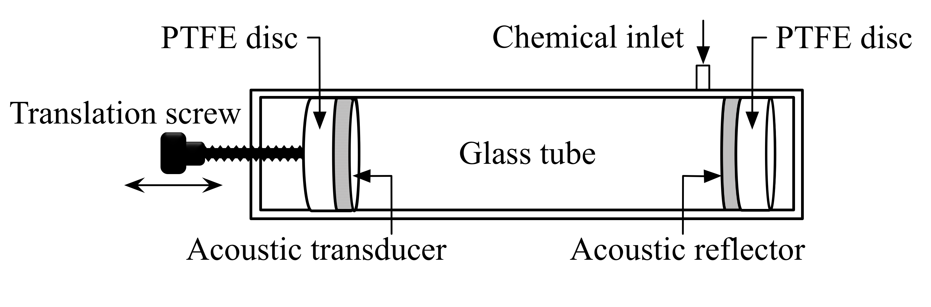
The main device body consists of a glass tube (Soham Scientific, Ely, UK) with an inner diameter of 30 mm. The space available for the monomer solution is confined within the glass tube by two circular discs made from polytetrafluoroethylene (PTFE). One incorporates a 2 MHz acoustic transducer of 25mm in diameter (Noliac, Denmark) whilst the other supports an acoustic reflector made from stainless steel. The distance between the transducer and the steel reflector can be regulated by a translation screw that converts rotary motion into the linear disc motion inside the glass tube (Figure 1).
| material | v | Z (MRayl) | R | |
|---|---|---|---|---|
| platinum | 3.26 | 21.40 | 84.74 | 0.966 |
| gold | 3.24 | 19.70 | 62.60 | 0.954 |
| stainless steel | 5.79 | 7.69 | 45.63 | 0.937 |
| copper | 5.01 | 8.93 | 41.46 | 0.931 |
| silver | 3.60 | 1.60 | 37.76 | 0.925 |
| brass | 4.70 | 8.64 | 37.30 | 0.924 |
| titanium | 8.27 | 5.15 | 27.69 | 0.899 |
| iron cast | 5.90 | 7.69 | 25.00 | 0.888 |
| lead | 2.20 | 11.20 | 24.49 | 0.886 |
| aluminium | 6.42 | 2.70 | 17.33 | 0.840 |
| glass silica | 5.90 | 2.20 | 13.00 | 0.796 |
| polystyrene | 2.34 | 1.04 | 2.47 | 0.251 |
To maximise the reflected acoustic waves so that energy is largely trapped in the tube, the acoustic reflector is selected to maximise the acoustic impedance mismatch between medium and reflector. The acoustic impedance of the monomer solution is assumed to equal water at 1.48 MRayl at 20∘C [4]. The properties of potential materials are listed in Table 1. They are sorted in descending order according to their reflection coefficient . Platinum or gold produces the best reflection performance, however for this application the stainless steel disc is more accessible and practical.
3.2 Polymeric phononic crystal fabrication
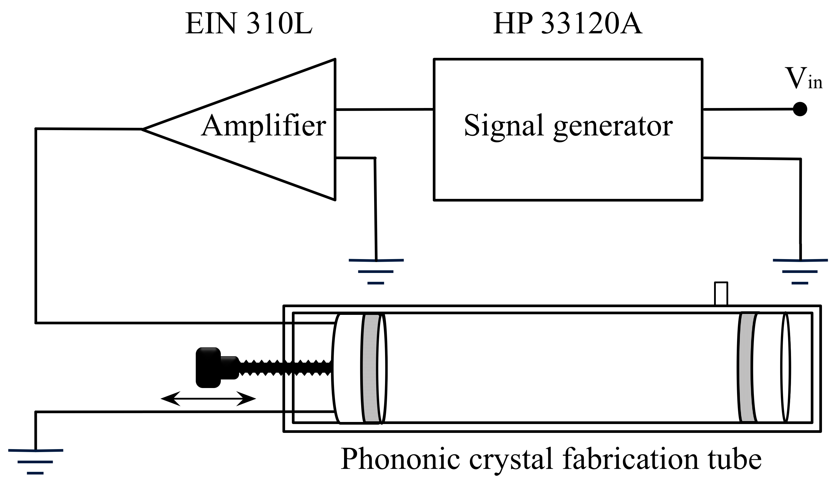
The periodic structure that emerges is associated with the acoustic standing wave field in the fabrication tube chamber. An HP 33120A signal generator in-line with an ENI 310L power amplifier is arranged to excite the piezo disc at its natural resonant frequency. Figure 2 illustrates the fabrication setup. A monomer/cross-linker solution containing 98.5 mol% acrylamide and 1.5 mol% N,N’-methylenebisacrylamide(MBA) is used to fill the fabrication tube. The chemical initiators, including 10%(w/v) freshly prepared ammonium persulfate (APS) and tetramethylethylenediamine (TEMED) are loaded and the chemical inlet sealed. The tube is shaken gently to achieve thorough mixing of the reagents. The device is left on the table in a secure horizontal position. The signal generator energises the piezo disc (Noliac Ceramics NCE51) at Vpp 90 mV at its resonant frequency. The translation screw knob is adjusted and a periodic structure forms in the tube that is clearly visible to the naked eye. The distance between the piezo disc and the stainless steel reflector is approximately 6 mm. The polymerisation process takes less than 1 min. The signal generator and the amplifier are switched off at a predetermined time corresponding to the onset of polymer rigidification.
3.3 Acoustic velocity measurement of the polymer
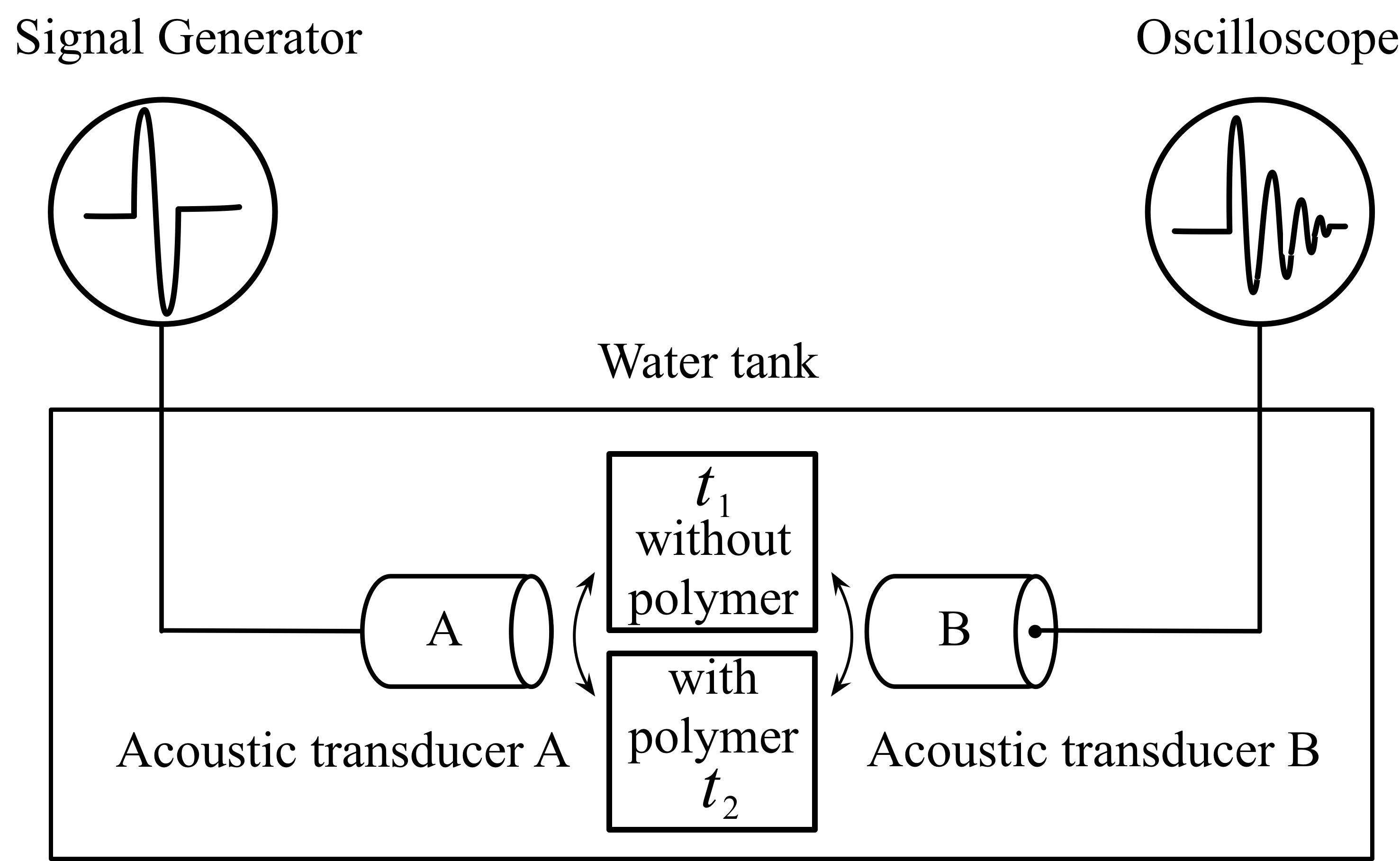
To investigate any slowing effect on acoustic waves we measured their average acoustic velocities and compared to their counterparts using a pulsed based setup. Figure 3 illustrates how the acoustic velocity through a polymer block is measured. An acoustic signal burst generated by the transducer A travels through the tank media to reach transducer B. If a polymer block is placed in path A-B a time difference results. Rearranging the time difference calculation Equation 4, Equation 5 gives the average acoustic velocity through the polymer alone, .
| (4) |
| (5) |
Where is the polymer thickness measured with a digital calliper. To minimise measurement error due to the polymer creep, hard plastic discs of known thickness are placed on either side of the polymer crystal during measurement. is the acoustic velocity in water and depends on temperature. used in this study is calculated from a quadratic equation =. This simplified equation is reasonably accurate over the 15-35∘C temperature range [16]. The coefficient are given in Table 2 and is the temperature of water in Celsius. The water temperature used for the velocity measurements is controlled at 23 0.2∘C and corresponds to 1491 m/s.
| 0 | 1404.30 |
|---|---|
| 1 | 4.70 |
| 2 | -0.04 |
4 Results and discussion
4.1 The polymeric crystal
The nature of the polymer crystal is related to the acoustic standing wave field and the shape of the fabrication tube. The process employed for making the polymer cyrstal is described in section 3.2. The resulting crystal after stabilisation is a 6mm thick polymer disc with a diameter of 30 mm. Importantly, the disc contains distinct layers that can be seen by the naked eye. To help interpret the nature of layers we consider a simplified approach here.
The mechanism determining the formation of the polymer crystal is still unconfirmed. Nevertheless the resulting patterns definitely emerge from pressure wave action on the monomer mix during the cross-linking process. If we move forward with a simple interpretative models, it is reasonable to conclude the rate of poylmer cross linking is proportional to the amplitude of the acoustic standing wave. Thus subject to the nodal or antinodal conditions the resulting material is likely to be biphasic, ie containing two different mechanical phases. Here the antinodes should produce a stiffer material and conversely at the nodes a less stiff material. Thus light passing through the polymer may experience a difference in propagation path leading to a visible contrast, which matches our experimental observations.
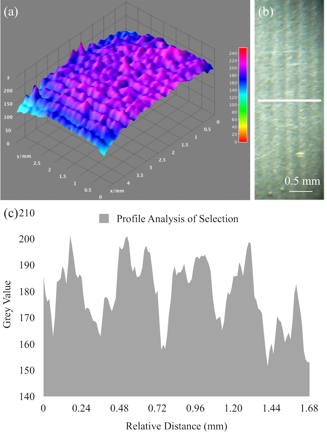
Optical microscopy was used to evaluate the quality of the crystals formed. A 1 mm thick piece of polymer crystal was used to assess line definition and spacing. This was sliced perpendicular to the radial plane with the cross-section facing the lens of a 4 magnification microscope. The grey values of the selected cross-section area is plotted as a 3D surface shown in Figure 5 (a). To assist with periodicity analysis, a profile analysis was performed and shown in Figure 5 (b). The pixel grey values along a line are presented in Figure 5 (c) -. Two light and shaded striations stand out signifying a biphasic material form. Based on an average wavelength of 0.7120.0077 mm (8 measurements) and a 2.16 MHz standing wave frequency the average acoustic velocity was found to be 1538 m/s, which is consistent with interpolated values for acoustic velocity vs. acrylamide concentration in Section 4.3. Here the patterns were coherent and consistently well-formed.
The transducer frequency determines the spacing in the crystal structure. The data shown in Figure 4 reveals the patterns can be formed with the periodicity decreasing proportionally with frequency. This is evidenced by the factor 2 increase in frequency yielding the expected factor 2 reduction in periodicity. Thus the microscopy data reveals contrast that is linked to material changes, so alternating bright and dark regions are a record of the acoustic field during crosslinking. However it is unproven whether the fluctuations in brightness are due to a mechanical periodicity.
4.2 The structurised polymer under scanning electron microscope (SEM)
SEM data was used to confirm mechanical periodicity in the polymer crystal. Here the SEM data in Figure 6 shows the cross-section topology is periodic indicating an underlying variation of ‘hills and valleys’ across the sample cross-section. Furthermore these regions include elongated voids and circular voids, confirming the recording of entrenched periodic mechanical properties by the standing wave. Thus it would imply the inherent potential to scatter an acoustic wave.
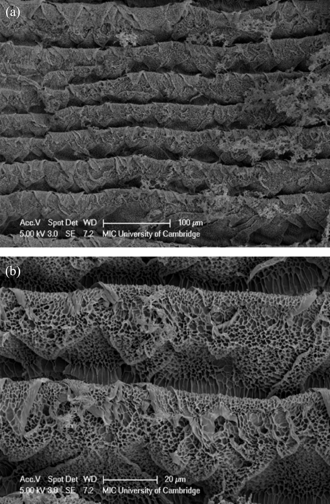
Freeze drying of the acrylamide polymers was found to reduce structural coherence by imposing unequal forces on the structure. Thus the SEM images which were useful in identifying the mechanical periodicity of polymer, also confirms that drying of the polymer will distort the structure. Thus water content does influence the coherence of these polymer crystals. As crystallisation patterns have been successfully recorded and confirmed the optical and SEM data it is useful to study acoustic wave transmission through them. In particular based on the theory of ”the slow wave effect” we investigate the important scattering and velocity relationship.
4.3 Average acoustic velocity across the polymer
We investigated the relation between the acoustic velocities of polymer crystals according to different polyacrylamide concentrations. As a reference point the signal from the counterpart material was also measured. These counterparts are fabricated in the same cavity device and corresponding acrylamide solutions, but during polymerisation the acoustic standing wave field is absent. Therefore no periodic structure emerges. The polymer explore acrylamide concentrations between 5 %(w/v) and 40 %(w/v) in 5 %(w/v) intervals.
The corresponding polymer acoustic velocities are presented in Figure 7. A positive linear correlation between the acrylamide concentration and average acoustic velocity is observed. The general linear model function in SPSS reveals a correlation between the concentration of acrylamide and acoustic velocity across the polymer crystal. The -value of interest is 0.001. The fact that it is smaller than the predetermined significance level 0.05 suggests these two fitting lines are independent.
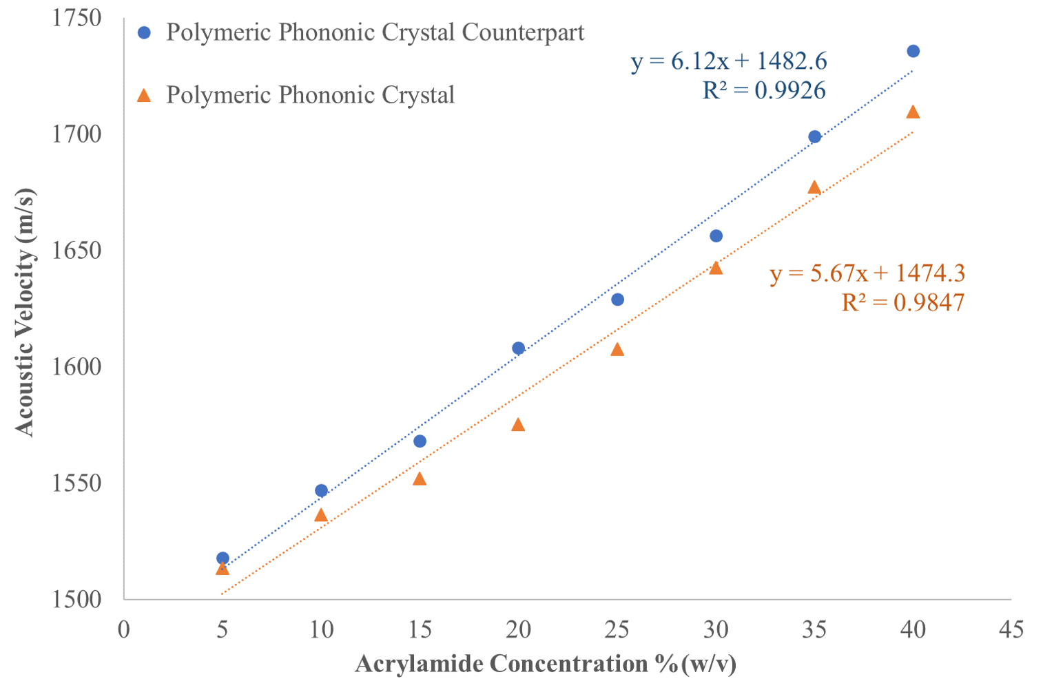
A key finding is the average acoustic velocity (at 1 MHz) of the polymer crystals is lower than their bulk polymer conterparts. This agrees with the slow wave effect. Here the periodic structure of a phononic crystal interacts with the waves. Although the temporal coherence is maintained with the incident acoustic wave, the scattering has a noticeable impact on the group velocity [21]. In Section 4.1 the optical evaluation of a slice of the polymer crystal indicates the average acoustic velocity through it is 1538 m/s. The monomer/cross-linker solution used in that experiment is 1.5 M equivalent to 10.85 %(w/v). Substitute the acrylamide factor with 10.85%(w/v) in the orange fitting line in Figure 7, it gives an average acoustic velocity 1536 m/s as a result in accordance with the optical evaluation value.
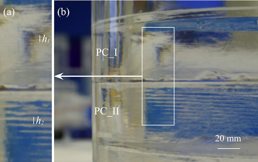
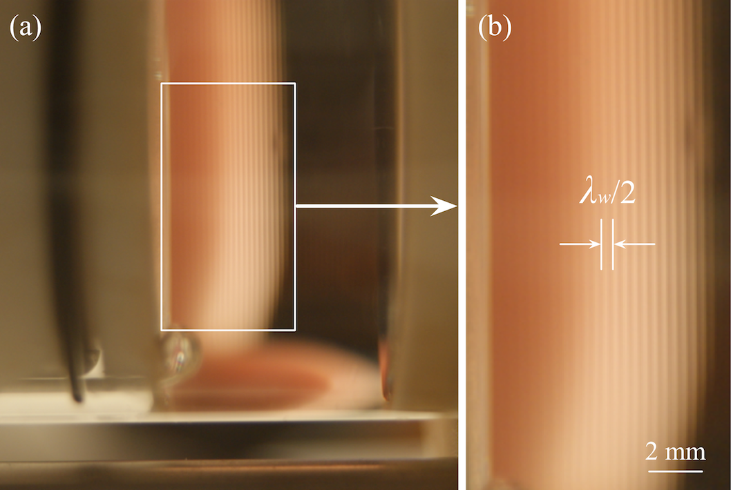
One may argue that when the monomer concentration is 0 %(w/v), the acoustic velocity tends to pure water , i.e. . The intercepts for both fitting lines thus should have been set at the acoustic velocity of water at ambient temperature. However, it must be noted for pure water, the acoustic standing wave still induces a periodic structure as shown in Figure 8. Thus the surprising result is that a temporary periodic field can also lead to a velocity shift.
The partitioning mechanism leading to the formation of a unique periodic structure in polyacrylamide is complex. Copolymerisation of acrylamide and MBA is already more involved than the standard free radical polymerisation [18]. One perspective is that when polymerisation is taking place a sequence of events occur in the micro-environment varying pressure and energy and physico-chemical conditions over time and space. This exacerbates polymerisation complexity. Thus a working hypothesis which is one of several yet to be confirmed, is that the acoustic standing waves promote a density differential over space. As the polymer chains elongate, they become insoluble and precipitate. These precipitates have a different density from the solution. As an acoustic pressure gradient from standing wave prevails, the partially polymerised matter moves towards the nodes. Meanwhile, the monomer concentration and cross-linker also affect the polymer elasticity modulus and density [2]. Overall more investigation of the event sequence is needed to isolate the mechanism.
5 Conclusion
A novel approach for fabricating polymeric phononic crystals with acoustic standing waves has been demonstrated. The cavity device follows a well established approach to create a standing wave field suitable for the polymer transformation. The starting form prior to cross-linking, comprises a 4 ml monomer/cross-linker solution plus polymerisation chemical initiators. The resulting form of the polymer crystal mirrors the cylindrical shape of the fabrication tube producing 30 distinctive layers. These have alternating refractive indices that are visible to naked eye.
The resultant polymeric phononic crystals were investigated by observing under an optical microscope and in transmission via an SEM. The latter provides detailed information on the periodic structure, the pore sizes in the polymer and the scale of the change. Visualising the periodic structure and determining its periodicity, provides an approximate calculation of the average acoustic velocity across the phononic crystal. The value 1538 m/s closely agrees with the interpolated value from the direct acoustic velocity measurements 1536 m/s. The refractive index differences can be attributed to variable monomer concentration affecting the elasticity. The acoustic velocity of pulses travelling through these phononic crystals and their counterparts are evaluated. The group velocity of the phononic crystals shows a lower acoustic velocity relative to counterparts of the same shape that omit periodic structures. These measurements match with theoretical studies of the behaviour of the slow wave effect in phononic crystals.
Contrasting with existing work this rapid fabrication approach does not necessitate the inclusion of particles, reducing complexity and saving fabrication time and costs. In its native form it is capable of creating unit cells from the standing wave planes adding important local resonance behaviour to the polymer. Thus it provides a significant shortcut for fabricating polymeric phononic crystals at both large and small scales within the time scale of one minute.
6 Acknowledgement
The authors are grateful to Dr Jeremy Skepper for assistance with SEM imaging of the sample and to Dr Ke Xu Zhou for helpful discussions on the mechanism. For part of this work, Dr Nan Li was funded by the Cambridge Overseas Trust.
7 References
References
- [1] Sarah Benchabane, Abdelkrim Khelif, J-Y Rauch, Laurent Robert, and Vincent Laude. Evidence for complete surface wave band gap in a piezoelectric phononic crystal. Physical Review E, 73(6):065601, 2006.
- [2] Vilhelm Bjerknes. Fields of force: supplementary lectures, applications to meteorology; a course of lectures in mathematical physics delivered December 1 to 23, 1905. Number 1. The Columbia university press, 1906.
- [3] Felix Bloch. Über die quantenmechanik der elektronen in kristallgittern. Zeitschrift für Physik A Hadrons and Nuclei, 52(7):555–600, 1929.
- [4] David L Bradley and Wayne D Wilson. Acoustic impedance of sea water as a function of temperature, pressure and salinity. Technical report, NAVAL ORDNANCE LAB WHITE OAK MD, 1966.
- [5] L Brillouin and M Parodi. Propagation of waves in periodic structures. Foreign literature, 1953.
- [6] Wei Cheng, Jianjun Wang, Ulrich Jonas, George Fytas, and Nikolaos Stefanou. Observation and tuning of hypersonic bandgaps in colloidal crystals. Nature materials, 5(10):830–836, 2006.
- [7] Y Cheng, JY Xu, and XJ Liu. Broad forbidden bands in parallel-coupled locally resonant ultrasonic metamaterials. Applied Physics Letters, 92(5):051913, 2008.
- [8] Nicholas Fang, Dongjuan Xi, Jianyi Xu, Muralidhar Ambati, Werayut Srituravanich, Cheng Sun, and Xiang Zhang. Ultrasonic metamaterials with negative modulus. Nature materials, 5(6):452–456, 2006.
- [9] Liang Feng, Xiao-Ping Liu, Ming-Hui Lu, Yan-Bin Chen, Yan-Feng Chen, Yi-Wei Mao, Jian Zi, Yong-Yuan Zhu, Shi-Ning Zhu, and Nai-Ben Ming. Acoustic backward-wave negative refractions in the second band of a sonic crystal. Physical review letters, 96(1):014301, 2006.
- [10] Jean-Numa Gillet, Yann Chalopin, and Sebastian Volz. Atomic-scale three-dimensional phononic crystals with a very low thermal conductivity to design crystalline thermoelectric devices. Journal of Heat Transfer, 131(4):043206, 2009.
- [11] Patrick E Hopkins, Charles M Reinke, Mehmet F Su, Roy H Olsson III, Eric A Shaner, Zayd C Leseman, Justin R Serrano, Leslie M Phinney, and Ihab El-Kady. Reduction in the thermal conductivity of single crystalline silicon by phononic crystal patterning. Nano letters, 11(1):107–112, 2010.
- [12] Manvir S Kushwaha, Peter Halevi, Leonard Dobrzynski, and Bahram Djafari-Rouhani. Acoustic band structure of periodic elastic composites. Physical review letters, 71(13):2022, 1993.
- [13] Vincent Laude, Mikaël Wilm, Sarah Benchabane, and Abdelkrim Khelif. Full band gap for surface acoustic waves in a piezoelectric phononic crystal. Physical Review E, 71(3):036607, 2005.
- [14] Damien Leduc, Bruno Morvan, Alain Tinel, Rebecca Sainidou, and Pascal Rembert. Magnetic-sphere-based phononic crystals. Crystals, 6(7):78, 2016.
- [15] Zhengyou Liu, Xixiang Zhang, Yiwei Mao, YY Zhu, Zhiyu Yang, Che Ting Chan, and Ping Sheng. Locally resonant sonic materials. Science, 289(5485):1734–1736, 2000.
- [16] J Lubbers and R Graaff. A simple and accurate formula for the sound velocity in water. Ultrasound in medicine & biology, 24(7):1065–1068, 1998.
- [17] F Lucklum and MJ Vellekoop. Rapid prototyping of 3d phononic crystals using high-resolution stereolithography fabrication. Procedia Engineering, 120:1095–1098, 2015.
- [18] KB McAuley. The chemistry and physics of polyacrylamide gel dosimeters: why they do and don’t work. In Journal of Physics: Conference Series, volume 3, page 29. IOP Publishing, 2004.
- [19] Robert C McMaster, Paul Mcintire, and Michael L Mester. Nondestructive testing handbook. Vol. 7: Ultrasonic testing ASNT. American Society for Nondestructive Testing, Inc, 4153 Arlington Plaza, Columbus, Ohio 43228, USA, 1986. 677, 1986.
- [20] Saeed Mohammadi and Ali Adibi. On chip complex signal processing devices using coupled phononic crystal slab resonators and waveguides. AIP Advances, 1(4):041903, 2011.
- [21] John H Page, Henry P Schriemer, IP Jones, Ping Sheng, and David A Weitz. Classical wave propagation in strongly scattering media. Physica A: Statistical Mechanics and its Applications, 241(1-2):64–71, 1997.
- [22] John H Page, Ping Sheng, Henry P Schriemer, I Jones, Xiaodun Jing, and David A Weitz. Group velocity in strongly scattering media. Science, pages 634–637, 1996.
- [23] Chunyin Qiu and Zhengyou Liu. Acoustic directional radiation and enhancement caused by band-edge states of two-dimensional phononic crystals. Applied physics letters, 89(6):063106, 2006.
- [24] Chunyin Qiu, Zhengyou Liu, Jing Shi, and CT Chan. Directional acoustic source based on the resonant cavity of two-dimensional phononic crystals. Applied Physics Letters, 86(22):224105, 2005.
- [25] R Sainidou, B Djafari-Rouhani, Y Pennec, and JO Vasseur. Locally resonant phononic crystals made of hollow spheres or cylinders. Physical Review B, 73(2):024302, 2006.
- [26] Kazuaki Sakoda. Optical properties of photonic crystals, volume 80. Springer Science & Business Media, 2004.
- [27] Henry P Schriemer, Michael L Cowan, John H Page, Ping Sheng, Zhengyou Liu, and David A Weitz. Energy velocity of diffusing waves in strongly scattering media. Physical Review Letters, 79(17):3166, 1997.
- [28] Tsung-Tsong Wu, Zi-Gui Huang, and S Lin. Surface and bulk acoustic waves in two-dimensional phononic crystal consisting of materials with general anisotropy. Physical review B, 69(9):094301, 2004.
- [29] Suxia Yang, John H Page, Zhengyou Liu, Michael L Cowan, Che Ting Chan, and Ping Sheng. Focusing of sound in a 3d phononic crystal. Physical review letters, 93(2):024301, 2004.
- [30] Xiangdong Zhang and Zhengyou Liu. Negative refraction of acoustic waves in two-dimensional phononic crystals. Applied Physics Letters, 85(2):341–343, 2004.