Extreme Asymmetry in Metasurfaces via Evanescent Fields Engineering: Angular-Asymmetric Absorption
Abstract
On the quest towards full control over wave propagation, the development of compact devices that allow asymmetric response is a challenge. In this Letter, we introduce a new paradigm for the engineering of asymmetry in planar structures, revealing and exploiting unilateral excitation of evanescent waves. We test the idea with the design and experimental characterization of a metasurface for angular-asymmetric absorption. The results show that the contrast ratio of absorption (the asymmetry level) can be arbitrarily engineered from zero to infinity for waves coming from two oppositely tilted angles. We demonstrate that the revealed asymmetry effects cannot be realized using conventional diffraction gratings, reflectarrays, and phase-gradient metasurfaces. This Letter opens up promising possibilities for wave manipulation via evanescent waves engineering with applications in one-side detection and sensing, angle-encoded steganography, flat nonlinear devices and shaping the scattering patterns of various objects.
Asymmetric wave propagation has attracted significant interest in recent years due to its fundamental importance in many applications, for example, in one-way communication systems. Many asymmetric properties (Faraday rotation, wave isolation, etc.) can be realized only using nonreciprocal components (e.g., ferrites Adam et al. (2002), nonlinear materials Fallahi and Perruisseau-Carrier (2012); Mahmoud et al. (2015), and materials with space-time modulated properties Sounas et al. (2013); Hadad et al. (2015)). However, some asymmetric propagation effects (asymmetric wave transmission, reflection, absorption) are reciprocal effects. Some interesting results have been achieved using artificial 2D composites, so-called metasurfaces Menzel et al. (2010); Mutlu et al. (2012); Huang et al. (2012); Zhang et al. (2013); Pfeiffer and Grbic (2014); Fedotov et al. (2006); Wu et al. (2013); Pfeiffer et al. (2014); Ra’di et al. (2014); Alaee et al. (2015a); Asadchy et al. (2015); Shevchenko et al. (2015); Odit et al. (2016); Yazdi et al. (2015); Alaee et al. (2015b); Faniayeu and Mizeikis (2017). Depending on the physics of the asymmetric response, the known structures can be classified to two main types. In the metasurfaces of the first type, asymmetric transmission or reflection is achieved due to asymmetric polarization conversion Menzel et al. (2010); Mutlu et al. (2012); Huang et al. (2012); Zhang et al. (2013); Pfeiffer and Grbic (2014); Fedotov et al. (2006); Wu et al. (2013); Pfeiffer et al. (2014). For example, a right circularly polarized beam is transmitted from medium 1 to medium 2 as a left circularly polarized beam, while the same right circularly polarized beam, when incident reciprocally from medium 2 to medium 1, is fully reflected, preserving its polarization state. Although such system exhibits unidirectional transmission for waves impinging on the two opposite sides, its scattering matrix is symmetric, as dictated by the reciprocity theorem. In metasurfaces of the second type, asymmetric response can be achieved without polarization conversion, but only for devices working in the reflection regime. In such devices, the asymmetry of reflection coefficient phase for illuminations from opposite sides was exploited in specifically designed bianisotropic metasurfaces Ra’di et al. (2014); Alaee et al. (2015a); Asadchy et al. (2015); Shevchenko et al. (2015); Odit et al. (2016); Asadchy et al. (2018). In lossy structures, asymmetric absorption becomes possible Yazdi et al. (2015); Alaee et al. (2015b); Faniayeu and Mizeikis (2017).
In the aforementioned works, asymmetric wave propagation was achieved only from different sides of composite layers and for normally incident waves. From the theoretical point of view and for many applications (e.g., multifunctional grating, flat optics), it is important to create planar structures with asymmetric response for illuminations from two half-spaces with respect to the normal direction of the surface or for two arbitrary angular sectors. In principle, if the metasurface allows induced currents in the normal to the surface plane direction, asymmetric reflection at oblique incidence angles can be realized simply by using arrays of tilted elements. An example is an array of small tilted mirrors, which looks transparent if we look along the mirror planes, but strongly reflective if we look from the orthogonal direction. More advanced angular-asymmetric wave propagation was reported in Ref. Pfeiffer and Grbic (2016). However, this geometry-induced mechanism has significant limitations: the desired performance can be achieved only for angle, and fabrication of nonplanar structures with tilted inclusions can be complicated. To the best of our knowledge, asymmetrically reflecting planar metasurfaces without normal polarization are not known.
In this Letter, we demonstrate that evanescent waves engineering can provide a robust platform to control the asymmetric response of metasurfaces for oblique incidence, as well as allow other new functionalities. As an example, we theoretically and experimentally validate angular-asymmetric absorption in impenetrable planar reciprocal surfaces, and we show that the asymmetry level and the incidence configuration can be arbitrarily defined. This structure exhibits extremely broken symmetry of absorption properties with respect to the incidence angle: nearly zero and nearly total absorption for waves incident from and angles, respectively. We demonstrate that, to achieve extreme angular asymmetry of absorption, one must ensure excitation of a proper set of evanescent waves propagating along the surface in the direction of the incident-wave wave vector. Moreover, the surface properties must vary quasicontinuously with discretization of at least 10 elements per one wavelength. Thus, conventional diffraction gratings Hutley (1982); Popov et al. (1990) and recently introduced metagratings Ra’di et al. (2017); Epstein and Rabinovich (2017); Ra’di and Alù (2018), which include not more than two elements per period (three elements per wavelength), cannot be exploited to create such asymmetric reflectors. Our design of an angular asymmetric absorber is based on gradient metasurfaces Yu et al. (2011); Asadchy et al. (2017), i.e., diffraction gratings with properties varying at a deeply subwavelength scale.
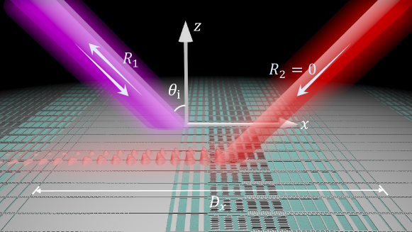
Let us consider an impenetrable reciprocal metasurface with periodicity along the direction, located in the plane (see Fig. 1). The metasurface is illuminated by a TE()-polarized plane wave at an incidence angle . Naturally, if the periodicity is smaller than a half-wavelength of the incident radiation (which is the case for conventional electromagnetic absorbers), the reflection and absorption are even functions with respect to angle . This fact originates from reciprocity of the system, which implies that specular reflections are the same for illuminations from and angles. In order to break the reflection symmetry of the metasurface, it is necessary (but not sufficient) to ensure its proper periodicity so that diffracted modes can propagate. In this case, waves incident from the opposite directions ( and ) can be reflected into diffracted harmonics and with different amplitudes. Therefore, although the specular reflection remains an even function of the incidence angle (due to reciprocity), absorption coefficient and total reflection become noneven functions. The field reflected by a periodically modulated metasurface can be interpreted as a sum of Floquet harmonics. The tangential wave number of the th harmonic is related to the period and the incident wave number as . The corresponding normal component of the reflected wave number equals . If is greater than the incident wave number, the wave is evanescent and it does not contribute to the far field. For the harmonic wave satisfying , is real, and this wave is propagating.
Our aim is to achieve controllable nonspecular reflection for waves incident on the metasurface at an angle and full absorption of waves incident at an angle . We will show that such asymmetric absorption can be achieved through unbalanced excitation of evanescent waves along the metasurface in these two cases (stronger evanescent waves contribute to higher energy dissipation at a lossy metasurface). To this end, we look for a solution when a few or none evanescent waves are excited for illumination at , while the opposite illumination results in multiple and strong evanescent harmonics.
First, let us consider illumination of the metasurface at an angle and require that the reflected field is represented only by one propagating harmonic with electric field amplitude , where is the incident electric field and is the reflection coefficient into that harmonic. Thus, we assume that no specular reflections are allowed and that no evanescent waves are excited for this illumination (in Ref. sup , we demonstrate that this scheme is the most efficient way to realize extremely asymmetric absorption). The tangential components of the total electric field at the plane can be written as , where the time-harmonic dependency in the form is assumed.
The corresponding total magnetic field reads , with being the free-space wave impedance. The ratio of these tangential electric and magnetic fields gives the required surface impedance
| (1) |
where is the linearly varying phase. The real part of the surface impedance is an even function of and always non-negative for passive () metasurfaces. In contrast, the imaginary part of the surface impedance is an odd function of which creates angular asymmetry of the electromagnetic response. As is seen from Eq. (1), the periodicity of the surface impedance is , where stands for the wavelength. Arrays with such periodicity allow only one propagating diffraction harmonic, and this scenario is sometimes referred in the literature as the Littrow configuration Loewen et al. (1977); Popov et al. (1990); Destouches et al. (2005) or retroreflection regime Doumanis et al. (2013).
If the metasurface with properties dictated by Eq. (1) is illuminated at the opposite angle (same polarization), the reflected fields do not contain a single plane wave anymore. Indeed, the incident field has reversed phase distribution , and, therefore, fulfillment of the boundary condition [Eq. (1)] is possible only if a certain set of evanescent waves is excited. These evanescent waves will contribute to additional power dissipation in the metasurface. The total reflected fields can be represented as an infinite sum of Floquet harmonic modes, , where is the complex amplitude of the th harmonic. The total tangential electric and magnetic fields at read
| (2) |
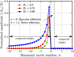
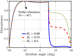
By enforcing the boundary condition, , we determine the amplitudes of all the Floquet harmonics using the method reported in Hwang (2012) (a MATLAB code can be downloaded from Ref. sup ). Figure 2 shows the determined complex magnitudes of harmonics for illumination at an angle [hereafter, as an example, we consider a metasurface designed for , i.e., with the periodicity ]. Three scenarios are illustrated, corresponding to three different surface impedance profiles [Eq. (1)], which were calculated assuming , , and . As is seen from Fig. 2, for all three scenarios, the magnitudes of propagating harmonics (specular refection) and (retroreflection with amplitude ) are zero, meaning that all of the incident energy is dissipated in the lossy metasurface. The reason of full absorption is excitation of an infinite set of evanescent harmonics. Note that all the excited evanescent modes are of negative order () and propagate along the direction. This effect highlights the role of evanescent fields as a mechanism of phase matching between the incident wave and the metasurface. Interestingly, the less absorption we require for the illumination at (the higher ), the stronger evanescent harmonics are excited for the illumination at , ensuring full absorption for that illumination direction. We can see that the contrast ratio of absorption, defined as , can be arbitrarily adjusted from zero to infinity by manipulating the amplitudes of evanescent harmonics. In all the three cases for different , the absorptance curve is extraordinarily asymmetric with respect to the incident angle, as shown in Fig. 2. The limiting case of is of special interest where the absorptance curve resembles the Heaviside step function. At the critical angle , where the mode becomes propagating or evanescent, the metasurface abruptly switches its response from an absorber to a reflector. Additionally, the frequency-domain response of the surface is discussed in Ref. sup .
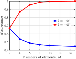
Before the implementation of the surface impedance [Eq. (1)], it is important to consider the influence of the impedance discretization on the metasurface performance. Figure 2 demonstrates how absorptance for illuminations at angles and depends on the number of sub-cells in each period (surface impedance is modeled by a step function with steps over a period). The data in the figure corresponds to the scenario when ; the discretization data for scenarios with other values of are plotted in Ref. sup . Thus, the asymmetry of absorptance strongly depends on the number of subelements and for higher asymmetry (higher ) a large number of small sub-cells is required. This fact shows that angle-asymmetric absorption is not possible to achieve using conventional gratings and “metagratings”. In our implementation, we synthesize the surface impedance with using sub-elements over a period. Such discretization ensures the proper excitation of evanescent waves over the metasurface (see detailed analysis of evanescent modes versus in Ref. sup ).
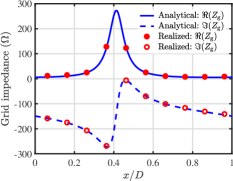
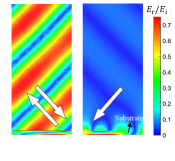
Next, we realize the required surface impedance at 75 GHz with a metallic pattern supported by a metal-backed dielectric slab [with the relative permittivity and thickness m]. Based on the transmission-line theory, the required sheet (or grid) impedance of the pattern can be expressed as Wang et al. (2018) , where and are the wave impedance and the normal component of the wave number in the dielectric. The calculated required grid impedance is shown in Fig. 2. Using full-wave simulations hfs , we analyze the reflected field from the ideal grid impedance discretized into 10 subcells on the metal-backed dielectric substrate [see Fig. 2]. The field distribution confirms that with subcells per period the metasurface possesses desired response: Retroreflection with the field amplitude of for illumination at and nearly full absorption (99.5%) for illumination at . In the latter case, strong evanescent fields are triggered in the vicinity of the metasurface in accordance with the theory, which induces total absorption with the presence of metal losses. It should be mentioned that the unilateral excitations of strong evanescent waves can have also other applications, for example, for creating nonreciprocal devices based on substrates with nonlinear properties.
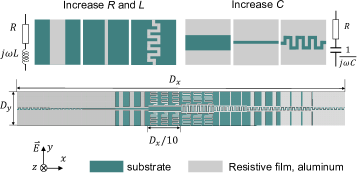
Next, we implement the complex grid impedances as 10 subcells. Here, we utilize a thin aluminum film with thickness of 25 nm and measured grid resistivity of /sq Wang et al. (2017). By structuring the homogeneous film, we can create the required grid resistance and reactance on a surface as shown in Fig. 2. The required resistance is realized by tailoring the width and length of the metallic strips. For the polarization of the incident wave shown in Fig. 2, the smaller width and the longer length result in higher grid resistance. Since such structures inherently contain some inductive characteristics (which increase when width decreases), we introduce a capacitive gap as another degree of freedom to control the grid reactance. Similarly, the capacitance of the gap can be increased by narrowing or meandering the gap, without affecting the resistive part. In this way, we can independently engineer the grid resistance and reactance. Following this method, all the subcells were optimized with geometrical dimensions specified in Ref. sup . Figure 2 (see circle points) shows that the realized grid impedances of the 10 subcells closely follow the required theoretical curve. Next, we combine together the sub-cells into one unit cell shown in Fig. 2. Without further optimization, the simulated results show retro-reflection , which is very close to the design target value of , and the reflection for the opposite illumination is (97.4% absorption). The specular reflectance for both illuminations is 2.7%.
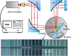
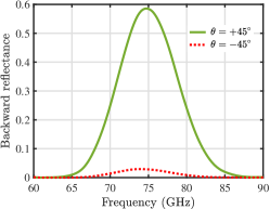
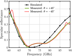
Figure 3 depicts the schematic of the experiment setup (see more details in Ref. sup ). The sample is fabricated using photolithography and lift-off process. Figure 3 shows the measured backward reflectance spectra (retroreflection squared) of the gradient metasurface illuminated at and . The results are in excellent agreement with the theory. At the operating frequency of 75 GHz, the measured backward reflectance for reaches 58.5% (versus theoretical ), while for it is equal to 2.8% (versus theoretical ). Figure 3 shows the specular reflectance for both illuminations. Due to reciprocity of the metasurface, the two measured curves are practically identical. At 75 GHz, only 5.6% of the incident power is specularly reflected (versus simulated 2.7%). Thus, the absorptance calculated from the measured data for illuminations at and is approximately 36% and 92%, respectively. Due to the fabrication limitations and material dispersion, one cannot infinitely scale down the structure dimensions to higher frequencies towards the visible range. However, the developed theory is rather general and applicable to the whole electromagnetic spectrum. It is worth mentioning that the presented structuring method is not a unique solution for the implementation of required impedance profiles. In optics, it is always possible to simplify the configurations of subelements or use high-permittivity dielectric cells to satisfy the required impedance boundary condition.
To summarize, we have demonstrated that evanescent waves excited in subwavelength gratings can be exploited to achieve extreme electromagnetic effects in planar structures. As a particular example of an effect that is not possible in conventional phase-gradient metasurfaces or diffraction gratings, we have demonstrated angular-asymmetric absorption and reflection. The concept of wave control via evanescent harmonics engineering can be scaled to other frequencies and applied to wave processes of different nature. In addition to its theoretical significance, it can have multiple practical outcomes. For example, by replacing the dielectric substrate of the metasurface by a nonlinear material, one can design various compact nonreciprocal devices. Since strong evanescent waves are excited only for one of the opposite illuminations, the effective permittivity of the nonlinear substrate will be different for these two cases. As a result, the metasurface response will not obey the Lorentz reciprocity theorem. Importantly, the amplitude of the waves impinging on the metasurface do not have to be large and can be the same for the opposite illuminations. Other important applications of the proposed angular-asymmetric structures include unidirectional emission, multifunctional gratings, systems for one-side detection, sensing and radar cross section control.
This work was supported by the Academy of Finland (Projects 288145, 287894, and 309421). The authors thank Jingwei Zhou (Aalto University) for technical discussions and Tapio Mkel (VTT) for his help in the fabrication.
References
- Adam et al. (2002) J. D. Adam, L. E. Davis, G. F. Dionne, E. F. Schloemann, and S. N. Stitzer, IEEE Trans. Microwave Theory Tech. 50, 721 (2002).
- Fallahi and Perruisseau-Carrier (2012) A. Fallahi and J. Perruisseau-Carrier, Appl. Phys. Lett. 101, 231605 (2012).
- Mahmoud et al. (2015) A. M. Mahmoud, A. R. Davoyan, and N. Engheta, Nat. Commun. 6, 8359 (2015).
- Sounas et al. (2013) D. L. Sounas, C. Caloz, and A. Alù, Nat. Commun. 4, 2407 (2013).
- Hadad et al. (2015) Y. Hadad, D. L. Sounas, and A. Alù, Phys. Rev. B 92, 100304 (2015).
- Menzel et al. (2010) C. Menzel, C. Helgert, C. Rockstuhl, E.-B. Kley, A. Tünnermann, T. Pertsch, and F. Lederer, Phys. Rev. Lett. 104, 253902 (2010).
- Mutlu et al. (2012) M. Mutlu, A. E. Akosman, A. E. Serebryannikov, and E. Ozbay, Phys. Rev. Lett. 108, 213905 (2012).
- Huang et al. (2012) C. Huang, Y. Feng, J. Zhao, Z. Wang, and T. Jiang, Phys. Rev. B 85, 195131 (2012).
- Zhang et al. (2013) S. Zhang, F. Liu, T. Zentgraf, and J. Li, Phys. Rev. A 88, 023823 (2013).
- Pfeiffer and Grbic (2014) C. Pfeiffer and A. Grbic, Phys. Rev. Appl. 2, 044011 (2014).
- Fedotov et al. (2006) V. A. Fedotov, P. L. Mladyonov, S. L. Prosvirnin, A. V. Rogacheva, Y. Chen, and N. I. Zheludev, Phys. Rev. Lett. 97, 167401 (2006).
- Wu et al. (2013) L. Wu, Z. Yang, Y. Cheng, M. Zhao, R. Gong, Y. Zheng, J. Duan, and X. Yuan, Appl. Phys. Lett. 103, 021903 (2013).
- Pfeiffer et al. (2014) C. Pfeiffer, C. Zhang, V. Ray, L. J. Guo, and A. Grbic, Phys. Rev. Lett. 113, 023902 (2014).
- Ra’di et al. (2014) Y. Ra’di, V. S. Asadchy, and S. A. Tretyakov, IEEE Trans. Antennas Propag. 62, 3749 (2014).
- Alaee et al. (2015a) R. Alaee, M. Albooyeh, A. Rahimzadegan, M. S. Mirmoosa, Y. S. Kivshar, and C. Rockstuhl, Phys. Rev. B 92, 245130 (2015a).
- Asadchy et al. (2015) V. S. Asadchy, Y. Ra’di, J. Vehmas, and S. A. Tretyakov, Phys. Rev. Lett. 114, 095503 (2015).
- Shevchenko et al. (2015) A. Shevchenko, V. Kivijarvi, P. Grahn, M. Kaivola, and K. Lindfors, Phys. Rev. Appl. 4, 024019 (2015).
- Odit et al. (2016) M. Odit, P. Kapitanova, P. Belov, R. Alaee, C. Rockstuhl, and Y. S. Kivshar, Appl. Phys. Lett. 108, 221903 (2016).
- Yazdi et al. (2015) M. Yazdi, M. Albooyeh, R. Alaee, V. Asadchy, N. Komjani, C. Rockstuhl, C. R. Simovski, and S. Tretyakov, IEEE Trans. Antennas Propag. 63, 3004 (2015).
- Alaee et al. (2015b) R. Alaee, M. Albooyeh, M. Yazdi, N. Komjani, C. Simovski, F. Lederer, and C. Rockstuhl, Phys. Rev. B 91, 115119 (2015b).
- Faniayeu and Mizeikis (2017) I. Faniayeu and V. Mizeikis, Appl. Phys. Exp. 10, 062001 (2017).
- Asadchy et al. (2018) V. S. Asadchy, A. Díaz-Rubio, and S. A. Tretyakov, Nanophotonics 7, 1069 (2018).
- Pfeiffer and Grbic (2016) C. Pfeiffer and A. Grbic, Phys. Rev. Lett. 117, 077401 (2016).
- Hutley (1982) M. C. Hutley, Diffraction gratings (Techniques of Physics) (Academic Press, London, 1982).
- Popov et al. (1990) E. Popov, L. Tsonev, and D. Maystre, J. Mod. Opt. 37, 367 (1990).
- Ra’di et al. (2017) Y. Ra’di, D. L. Sounas, and A. Alù, Phys. Rev. Lett. 119, 067404 (2017).
- Epstein and Rabinovich (2017) A. Epstein and O. Rabinovich, Phys. Rev. Appl. 8, 054037 (2017).
- Ra’di and Alù (2018) Y. Ra’di and A. Alù, ACS Photonics 5, 1779 (2018), https://doi.org/10.1021/acsphotonics.7b01528 .
- Yu et al. (2011) N. Yu, P. Genevet, M. A. Kats, F. Aieta, J.-P. Tetienne, F. Capasso, and Z. Gaburro, Science 334, 333 (2011).
- Asadchy et al. (2017) V. S. Asadchy, D.-R. A, S. N. Tcvetkova, D.-H. Kwon, A. Elsakka, M. Albooyeh, and S. A. Tretyakov, Phys. Rev. X 7, 031046 (2017).
- (31) See Supplemental Material for additional information on optimal configuration for extremely asymmetric absorption, frequency dependence of absorptance, effect of discretization accuracy on the absorption asymmetry, and implementation method.
- Loewen et al. (1977) E. G. Loewen, M. Nevière, and D. Maystre, Appl. Opt. 16, 2711 (1977).
- Destouches et al. (2005) N. Destouches, A. V. Tishchenko, J. C. Pommier, S. Reynaud, O. Parriaux, S. Tonchev, and M. A. Ahmed, Opt. Exp. 13, 3230 (2005).
- Doumanis et al. (2013) E. Doumanis, G. Goussetis, G. Papageorgiou, V. Fusco, R. Cahill, and D. Linton, IEEE Trans. Antennas Propag. 61, 232 (2013).
- Hwang (2012) R.-B. R. Hwang, Periodic Structures: Mode-Matching Approach and Applications in Electromagnetic Engineering (John Wiley & Sons, New York, 2012).
- Wang et al. (2018) X.-C. Wang, A. Díaz-Rubio, A. Sneck, A. Alastalo, T. Mäkelä, J. Ala-Laurinaho, J.-F. Zheng, A. V. Räisänen, and S. A. Tretyakov, IEEE Trans. Antennas and Propag. 66, 1340 (2018).
- (37) ANSYS HFSS 15, www.ansys.com.
- Wang et al. (2017) X.-C. Wang, A. Díaz-Rubio, and S. A. Tretyakov, IEEE Trans. Microwave Theory Tech. 65, 5009 (2017).