figure \cftpagenumbersofftable
Polarized Beam Patterns from a Multi-Moded Feed For Observations of the Cosmic Microwave Background
Abstract
We measure linearly polarized beam patterns for a multi-moded concentrator and compare the results to a simple model based on geometric optics. We convolve the measured co-polar and cross-polar beams with simulated maps of CMB polarization to estimate the amplitude of the systematic error resulting from the cross-polar beam response. The un-corrected error signal has typical amplitude of 3 nK, corresponding to inflationary B-mode amplitude . Convolving the measured cross-polar beam pattern with maps of the CMB E-mode polarization provides a template for correcting the cross-polar response, reducing it to negligible levels.
keywords:
beam pattern, polarimeter, cosmic microwave background* Address all correspondence to: Alan Kogut, \linkablealan.j.kogut@nasa.gov
1 Introduction
Linear polarization of the cosmic microwave background provides a unique window into the physics of the early universe. Gravitational waves created during an inflationary epoch interact with the CMB at later times to impart a distinctive signature in linear polarization. For the simplest (single-field) inflation models, the amplitude of this B-mode signal depends on the energy scale of inflation as
| (1) |
where is the power ratio of gravitational waves to density fluctuations [1]. Current measurements set upper limits at 95% confidence [2]. If inflation results from Grand Unified Theory physics (energy GeV), the B-mode amplitude should be of order 30 nK. Signals at this level could be detected by a dedicated polarimeter, providing a critical test of a central component of modern cosmology.
The inflationary signal is faint compared to the fundamental limit imposed by photon noise statistics for a single-moded detector in a one-second integration. Even ideal (noiseless) detectors suffer from this limit; the only solution is to collect more photons. The light-gathering ability of a detector can be specified by its etendu , where is the detector area and is the solid angle. Increasing the etendu adds modes, thereby increasing both the signal and the photon noise. The modes are independent, so that the noise increases as the square root of the etendu . But since the signal increases linearly with etendu, the signal-to-noise ratio improves as , increasing the overall system sensitivity.
A common implementation for CMB polarization increases the instrument etendu using a focal plane tiled with thousands of detectors (for a recent review, see [3]). These systems typically couple the detector to the sky using optical structures (feed horn, lenslet, phased antenna array) which restrict the system response to a single electromagnetic mode at the sensor. Single-moded systems achieve diffraction-limited angular resolution with well-defined (Gaussian) beam profiles, but the large number of sensors required drives system-level complexity and cost, both directly and through the accompanying need for cryogenic multiplexing to reduce the wire count to cold stages of the instrument.
Multi-moded sensors provide an alternative design solution. The beam width of a diffraction-limited system observing a single polarization state in a single mode scales with wavelength, . In a multi-moded system, the etendu is fixed so that the number of modes scales as . The different electromagnetic modes form an orthogonal basis set and add incoherently at the detector. Assuming nearly equal occupancy for most modes, the detector sensitivity then scales as . For detector area , the number of modes is large, allowing a corresponding reduction in detector count compared to a single-moded system of comparable sensitivity.

The Primordial Inflation Explorer (PIXIE) [4, 5] is a mission concept to measure CMB polarization at levels . PIXIE combines four multi-moded detectors with a polarizing Fourier transform spectrometer (FTS) to achieve background-limited sensitivity across a broad frequency range. Figure 1 shows the optical design. A pair of primary mirrors 55 cm in diameter produce two co-aligned beams on the sky. Folding flats and secondary mirrors transfer the beams to the FTS, which mixes the beams and introduces an optical phase delay. The recombined beams are then routed to a pair of non-imaging concentrators, each of which contains two multi-moded bolometric detectors to sense the fringe pattern as a function of optical phase delay. The instrument etendu of 400 mm2 sr corresponds to flat-topped beam with full width at half maximum 2.6∘ on the sky, and is conserved throughout the optical path.
An important aspect of the proposed instrument design is the use of non-imaging concentrators to couple light from the FTS to the detectors. Each detector is sensitive to a single linear polarization; any cross-polar response to the orthogonal polarization produces an effective rotation of the measured polarization with respect to the true polarization on the sky. The cross-polar response of single-moded structures is well understood. A corrugated circular feedhorn, for example, will typically exhibit cross-polarization at levels -25 dB with a distinctive quadrupolar (cloverleaf) angular pattern [6]. The cross-polar response of multi-moded structures is more complicated. We describe measurements and modeling of the co-polar and cross-polar beam patterns for a rectangular multi-moded concentrator designed for the PIXIE polarimeter, and assess the impact of the measured cross-polar response for measurements of the inflationary polarization signal.
2 Multi-Moded Concentrator Design
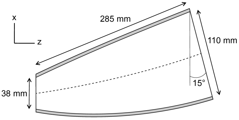
Figure 2 shows the concentrator design, which transforms the beam from the FTS to a sr solid angle at the detector. To preserve linear polarization, the concentrator has a rectangular cross section, with 4 walls each of which forms an elliptical section. Each concentrator contains a pair of polarization-sensitive bolometers, mounted within an integrating cavity at the exit aperture of the concentrator. Each bolometer detects a single linear polarization; the pair are mounted with their polarization directions rotated by 90∘ to measure orthogonal polarization states.
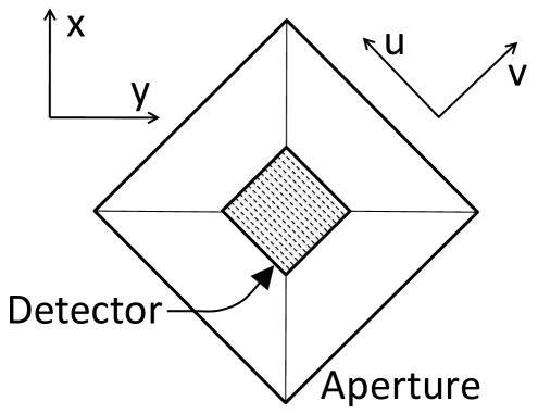
Light from the FTS enters the concentrator at an angle of 15∘ from the axis. The concentrator design minimizes the resulting asymmetry in the polarized beam patterns by rotating the concentrator 45∘ about the axis. Since the instrument remains symmetric from side to side ( to ), the rotated concentrator has two identical “top” walls and two identical“bottom” walls, with the top and bottom figures described by different elliptical sections. The detectors are mounted behind the square exit aperture formed by the four walls, and are necessarily aligned with the concentrator walls. In terms of the instrument coordinate system, we may write the detector polarizations as
| (2) |
with one detector sensitive to rotated 45∘ counter-clockwise from the vertical () and the other sensitive to rotated 45∘ clockwise (Fig. 3). Since the detector coordinates are symmetric with respect to any top–bottom () asymmetry, the polarized beam patterns from the detector pair are correspondingly symmetric. 111 A previous version[7] of the concentrator did not employ this 45∘ rotation and had a poorer match between the beams.
| Measurement | Sky | Number of Modes |
|---|---|---|
| Frequency | Frequency | |
| 10.8 GHz | 32 GHz | 5 |
| 35 GHz | 105 GHz | 49 |
| 91 GHz | 273 GHz | 330 |
3 Polarized Beam Pattern Measurements
We measured the co-polar and cross-polar beam patterns of a scaled version of the PIXIE concentrator. Measurements took place within the Goddard Electromagnetic Anechoic Chamber (GEMAC) facility and are similar to previous measurements described in [7]. Briefly, we transmit power in a single linear polarization and use an unpolarized Thomas Keating THz absolute power meter to record the power at the concentrator as a function of angle from the point-source transmitter. A wire grating between the power meter and the exit aperture of the concentrator defines the polarization state at the power meter. The grating can be rotated to sample either the or polarization. An absorbing iris at entrance aperture of the concentrator truncates the corners of the aperture and serves as a beam stop to circularize the beam patterns.
Although PIXIE’s FTS has frequency response to THz frequencies, the fixed noise of the power meter and the limited broadcast power available at frequencies above 100 GHz make direct measurements at higher frequencies impractical. Instead, we increase all dimensions of the PIXIE concentrator by a factor of three, and measure the beam patterns of the scaled concentrator at frequencies 10.8 GHz, 35 GHz, and 91 GHz corresponding to sky measurements of 32 GHz, 105 GHz, and 273 GHz for the un-scaled concentrator. The frequencies are selected to measure the beam pattern in the few-mode limit, the multi-moded geometric optics limit, and an intermediate case (Table 1). Note that the frequency spectrum of the CMB polarization follows the derivative of a blackbody spectrum, and peaks at frequencies near 270 GHz well into multi-moded operation. GEMAC data at 91 GHz sample the beam pattern near this peak.

The measured beam patterns include the response of the concentrator as well as the detector. The PIXIE detectors use silicon wires degeneratively doped with phosphorus to absorb light in a single linear polarization [8]. The measured beam patterns use a wire grating to reflect light in a single linear polarization, then measuring the transmitted light in the orthogonal polarization using an unpolarized power meter. The geometry of the power meter aperture and its location within the integrating cavity, as well as the position of the reflective wire grating, are appropriately scaled to match the detector for the PIXIE FTS.
Figure 4 shows the co-polar beam patterns measured at 35 GHz with the scaled concentrator (corresponding to 105 GHz for the unscaled design). The top panel shows slices through the flat-topped beam in the left–right (instrument to ) and up–down (instrument to ) directions. As expected, the beam patterns are symmetric with respect to but show a few-dB “tilt” in from the off-axis illumination. The bottom panel shows the beam patterns along and slices (bottom row) correspond to the detector and coordinate directions. Note that for all four slices, the co-polar beam pattern sampled by the detector is nearly identical to the pattern sampled by the orthogonal detector. This minimizes temperature–polarization mixing between unpolarized (temperature) gradients and the smaller polarized sky signal.
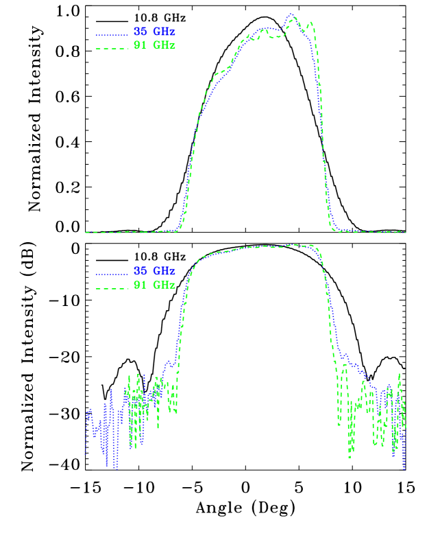
Figure 5 compares a slice through the copolar beam in the orientation at each of the mapped frequencies. The beam profile is similar at 35 and 91 GHz but broadens at 10.8 GHz where diffraction plays a more significant a role.
The co-polar beam patterns measure the response of the concentrator to a linearly polarized plane wave, when the polarization of the incident beam matches the polarization accepted by the detector (e.g. incident polarization measured by the detector). We also measure the cross-polar response when the detector is orthogonal to the incident polarization ( incident polarization measured by the detector). Figure 6 shows the cross-polar beam pattern measured at 35 GHz. As with Fig 4, we show the cross-polar response in 4 slices through the flat-topped beam, corresponding to the principal instrument ( and ) and detector ( and ) symmetries.

The cross-polar beam pattern has a similar flat-topped shape as the co-polar beam, but at a reduced amplitude. The dominant effect of the cross-polar response is a modest reduction in polarization efficiency (Table 2). The measured beam patterns correspond to polarization efficiency of 0.95, nearly independent of frequency. The polarization efficiency reduces the instrument response to a linearly polarized sky signal, and may be absorbed into the instrument calibration. It thus affects instrument signal-to-noise estimates, but does not induce systematic error in the measured sky polarization.
4 Comparison with Model
We model the co-polar and cross-polar beam patterns using a ray-trace code in the geometric optics limit. As discussed in [7], we account for operation in the few-mode limit by first binning the modeled beam pattern on a rectangular grid, Fourier transforming the binned beam map, sorting the complex Fourier coefficients by angular frequency, and Fourier transforming back to real space using only the lowest values. This removes the high spatial frequency information from the modeled beam pattern, approximating the effect of few-mode operation without computationally expensive phase matching. We then convolve the mode-truncated pattern with the Airy pattern for the appropriate observing frequency to approximate the effects of diffraction at the iris.
| Measurement | Polarization |
|---|---|
| Frequency | Efficiency |
| 10.8 GHz | 0.96 |
| 35 GHz | 0.93 |
| 91 GHz | 0.95 |
Figure 7 compares the co-polar and cross-polar beam patterns at measured frequency 35 GHz. Data and model agree well across the flat-topped beam, with rms difference 0.7 dB in both the co-polar and cross-polar response for either or polarization. The agreement between the measured and modeled beam patterns highlights the utility of the simple model technique. Direct electromagnetic computation of beam patterns through software code such as CST or HFSS requires amplitude and phase matching for each mode. A large number of modes in an off-axis geometry requires long computational times for a single configuration, becoming prohibitive for a design process with multiple iterations. The ray-trace code is simple, fast, and readily accounts for effects including off-axis orientation and complex detector geometries while retaining accurate modeling of both the co-polar and cross-polar beam response.

5 Discussion
Each PIXIE detector samples a single linear polarization (Stokes in instrument-fixed coordinates). The instrument rotates about the beam boresight to modulate the sky signal, allowing reconstruction of Stokes and parameters for each independent pixel on the sky [4]. Structure within the cross-polar response on angular scales smaller than the beam width can generate systematic error in the reconstructed sky signal. We estimate the magnitude of this effect by convolving the measured co-polar and cross-polar beam patterns with Monte Carlo simulations of polarized CMB sky signals.
The beam patterns for the full PIXIE instrument depend on both the concentrator and the fore-optics. Ray-trace modeling shows that the cross-polar response is dominated by the concentrator. We thus use the beam patterns measured for the scaled concentrator to estimate the systematic error resulting from the cross-polar beam response of the full instrument. The concentrator is designed to illuminate the transfer mirror T5 coupling the detectors to the spectrometer. The measured beam widths of the concentrator thus do not represent the width of the final PIXIE beams on the sky. However, since the optics conserve beam etendu, we may approximate the final beam on the sky by scaling the measured co-polar and cross-polar beam patterns by the diameter ratio of the 112 mm coupling mirror used for beam measurements to the PIXIE 550 mm primary mirror. The resulting beam has a diameter of 2.6∘.
We generate random realizations of CMB polarization using a standard CDM cosmology [9], evaluated to harmonic moment (angular scale 7). We convolve the simulated Stokes and maps with the scaled beam to generate the instrument response at fixed spin angle , then rotate the beam with respect to the sky and repeat for 32 angular steps uniformly covering spin angle [0, ]. Although the PIXIE fore-optics and FTS interfere the signals from two co-pointed beams, we ignore any additional cancellation of beam effects from the fore-optics and simply scale the beam patterns measured from the concentrator. The resulting signal is thus an upper limit to the systematic error expected from the full PIXIE optical system.

Figure 8 shows the resulting systematic error signal for two complete rotations of the beam over the simulated sky. The solid line shows the effect of the cross-polar response of the scaled 35 GHz beam (corresponding to 105 GHz sky signal). The “tilt” in the beam from the off-axis illumination modulates the response at the spin period. Since a true polarization signal is modulated twice per spin, the tilt does not contribute to the reconstructed polarization. We fit the simulated data to azimuthal spin modes,
| (3) |
where denotes the azimuthal order. The dotted line shows the dipole () component. The component (dashed line) is degenerate with true sky polarization, but is substantially smaller. We repeat the analysis for 100 realizations of the CMB sky. The systematic error component has mean amplitude nK with standard deviation 1.7 nK. Compared to the inflationary B-modes, the error from the measured cross-polar response corresponds to mean with standard deviation . Note that this represents an upper limit to the potential systematic error before correction. CMB polarization is dominated by the E-mode component. The measured cross-polar beam pattern may be convolved with maps of the E-mode polarization to correct the cross-polar response, further reducing its effect on B-mode searches.
6 Conclusion
We measure the co-polar and cross-polar beam patterns from a multi-moded concentrator designed for the PIXIE polarimeter. The beams provide a flat-topped pattern on the sky and are fully symmetrized between orthogonal linear polarizations. The cross-polar beam pattern has similar angular dependence as the co-polar beam; the dominant effect of the cross-polar response is a reduction in polarization efficiency to a measured efficiency of 95%. Structure in the cross-polar response on angular scales smaller than the 2.6∘ co-polar beam creates a systematic error when reconstructing the polarization signal from the sky. Monte Carlo simulations show the un-corrected error signal to have mean amplitude nK, corresponding to an error for the inflationary B-mode signal. Convolving the measured cross-polar beam pattern with maps of the CMB E-mode polarization provides a template for correcting the cross-polar response, reducing it to negligible levels.
Acknowledgements.
The authors gratefully acknowledge the assistance of G. De Amici and S. Seufert for measurements of the polarized beam patterns.References
- [1] D. H. D. H. Lyth and A. A. Riotto, “Particle physics models of inflation and the cosmological density perturbation,” Physics Reports 314, 1–146 (1999).
- [2] BICEP2 Collaboration, Keck Array Collaboration, P. A. R. Ade, et al., “Improved Constraints on Cosmology and Foregrounds from BICEP2 and Keck Array Cosmic Microwave Background Data with Inclusion of 95 GHz Band,” Physical Review Letters 116, 031302 (2016).
- [3] M. H. Abitbol, Z. Ahmed, D. Barron, et al., “CMB-S4 Technology Book, First Edition,” ArXiv e-prints (2017).
- [4] A. Kogut, D. J. Fixsen, D. T. Chuss, et al., “The Primordial Inflation Explorer (PIXIE): a nulling polarimeter for cosmic microwave background observations,” Journal of Cosmology and Astroparticle Physics 7, 025 (2011).
- [5] A. Kogut, J. Chluba, D. J. Fixsen, et al., “The Primordial Inflation Explorer (PIXIE),” in Space Telescopes and Instrumentation 2016: Optical, Infrared, and Millimeter Wave, Proceedings of the SPIE 9904, 99040W (2016).
- [6] P. Kildal, Foundations of Antennas: A Unified Approach, PROFESSIONAL PUB SERV (2000).
- [7] A. Kogut, D. J. Fixsen, and R. S. Hill, “Polarization properties of a broadband multi-moded concentrator,” Journal of the Optical Society of America A 32, 1040 (2015).
- [8] P. C. Nagler, K. T. Crowley, K. L. Denis, et al., “Multimode bolometer development for the PIXIE instrument,” in Millimeter, Submillimeter, and Far-Infrared Detectors and Instrumentation for Astronomy VIII, Proceedings of the SPIE 9914, 99141A (2016).
- [9] Planck Collaboration, P. A. R. Ade, N. Aghanim, et al., “Planck 2015 results. XIII. Cosmological parameters,” Astronomy and Astrophysics 594, A13 (2016).
Alan Kogut is an astrophysicist at NASA’s Goddard Space Flight Center. He received his A.B. from Princeton University and his PhD from the University of California at Berkeley. His research focuses on observations of the frequency spectrum and linear polarization of the cosmic microwave background and diffuse astrophysical foregrounds at millimeter and sub-mm wavelengths.
Dale Fixsen is an astrophysicist at the University of Maryland. He received his B.S. from Pacific Lutheran University, Tacoma Washington and his PhD from Princeton University. His research focuses on the spectrum, temperature, and polarization of the cosmic microwave background and the radio and infrared cosmic backgrounds.