Dynamics of magnetic skyrmion clusters driven by spin-polarized current with a spatially varied polarization
Abstract
Magnetic skyrmions are promising candidates for future information technology. Here, we present a micromagnetic study of isolated skyrmions and skyrmion clusters in ferromagnetic nanodisks driven by the spin-polarized current with spatially varied polarization. The current-driven skyrmion clusters can be either dynamic steady or static, depending on the spatially varied polarization profile. For the dynamic steady state, the skyrmion cluster moves in a circle in the nanodisk, while for the static state, the skyrmion cluster is static. The frequency of the circular motion of skyrmion is also studied. Furthermore, the dependence of the skyrmion cluster dynamics on the magnetic anisotropy and Dzyaloshinskii-Moriya interaction is investigated. Our results may provide a pathway to realize magnetic skyrmion cluster based devices.
Index Terms:
Magnetism in solids, magnetic skyrmion, spin current, spintronics, micromagnetics.I Introduction
Magnetic skyrmions are topologically protected quasi-particles usually stabilized by the Dzyaloshinskii-Moriya interaction (DMI) [1, 2, 3, 4]. The DMI in the bulk magnetic materials with broken inversion symmetry can result in the formation of Bloch-type skyrmions [5]. The DMI originating from the interface between ultra-thin magnetic film and a transition metal can lead to the formation of Néel-type skyrmions [6]. Because skyrmions can have small size and reasonable stability, many potential spintronic and electronic applications based on skyrmions have been proposed [7, 8, 9, 10, 11, 12, 15, 13, 14, 16]. The ability to create and observe skyrmions experimentally has further enhanced their competitiveness [17, 5, 18, 19, 6, 20, 21]. Moreover, skyrmions can be manipulated by a number of methods, such as spin-polarized current [7, 22, 23], spin wave [24, 25], and magnetic field [26, 27], which diversifies the application of skyrmions. For the magnetic field, uniform fields in symmetric systems cannot move skyrmions but one needs to break the in-plane symmetry, such as applying an additional in-plane field [26] or a field gradient [28, 29].
In this Letter, we show that the isolated skyrmion and skyrmion cluster [30, 31, 32] in a ferromagnetic nanodisk with interface-induced DMI can be manipulated by the spin-polarized current with a spatially varied polarization, e.g., a vortex-like polarization. Such a vortex-like polarization is assumed to be realized by a vortex polarizer, which has been used to improve the performance of nano-oscillators in previous literature [33, 34]. The skyrmions driven by the spin-polarized current with a vortex-like polarization can reach either a dynamic steady state or a static state, depending on the profile of the spatially varied polarization. With applying the vertical spin current, some of the skyrmions in the skyrmion cluster are destroyed. For the dynamic steady state, the remaining skyrmions move in a circle in the final state, while for the static state, the remaining skyrmions are static. Hence, using the spin-polarized current with a vortex-like polarization, it is possible to rotate, assemble, compress and delete skyrmions in the nanodisk in a quantitative manner.
II Methods
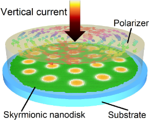
The simulation model, as shown in Fig. 1, is an ultra-thin ferromagnetic nanodisk with the thickness of nm and the diameter of nm on a heavy-metal substrate inducing DMI. The micromagnetic simulations are performed with the Object Oriented MicroMagnetic Framework (OOMMF) simulator [35]. The dynamics of magnetization is described by the Landau-Lifshitz-Gilbert (LLG) equation including a Slonczewski-like torque, written as
| (1) |
where is the reduced magnetization , is the saturation magnetization, is the gyromagnetic ratio and is the damping coefficient, is the effective field including the contributions of Heisenberg exchange, DMI, perpendicular magnetic anisotropy (PMA) and demagnetization field. The variable is defined as , where is the reduced Plank constant, is the current density, is the assumed full spin polarization rate, is the nanodisk thickness, is the electron charge, is the vacuum permeability constant, and is the spin polarization. We consider four cases of the spatially varied polarization profile , which could be realized by a vortex polarizer, as shown in Fig. 2 (a) in the left-most column. While the field-like torque can occur in relevant systems, it is not included in this study because we have checked and found that the effect of field-like torque on the skyrmion dynamics is small.
The model is discretized into cuboidal volume elements with the size of nm nm nm. The default DMI constant is mJ/m2. For the phase diagrams, DMI constant varies from mJ/m2 to mJ/m2 with a step of mJ/m2. The interfacial DMI strength can be controlled by varying the thickness of the underlying heavy metal layer [36]. The saturation magnetization is kA/m. The exchange constant is pJ/m. The PMA constant varies from MJ/m3 to MJ/m3. The Gilbert damping coefficient ranges to . The spin-polarized current injection area is a circle with a diameter of nm upon the nanodisk. The current density is in the range of MA/cm2. The Oersted field is not included for all the simulations. Initially, an isolated skyrmion or skyrmion cluster has been created in the nanodisk and relaxed into stable state. The skyrmion cluster is composed of skyrmions in our simulations.
III Results and Discussion
III-A Manipulating the isolated skyrmion
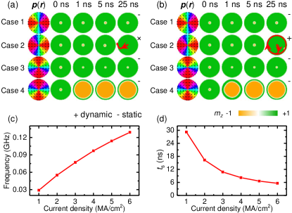
We first study the manipulation of an isolated skyrmion driven by the spin current with the spatially varied polarization. Initially, an isolated skyrmion is placed at the nanodisk center and relaxed. The results for and are shown in Fig. 2(a) and (b), respectively. The case 1 and 2 are corresponding to the outward-pointing and inward-pointing radial polarization profiles, respectively. The case 3 and 4 corresponds to the counterclockwise and clockwise vortex-like polarization profiles, respectively. For case 1, the skyrmion doesn’t move when the spin current is injected. For case 2, the skyrmion stays at its initial position for ns. It can be seen from the second row of Fig. 2(a), the skyrmion shifts from the center of the nanodisk slightly when ns. Finally, the skyrmion is destroyed by touching the nanodisk edge. The trajectory of the skyrmion is indicated by the red curve. For case 3, when the spin current is applied, the radius of skyrmion shrinks from nm to nm. For case 4, the skyrmion size expands and the size is comparable to the size of nanodisk finally. In Fig. 2(b), for , similar results can be found for different polarization profiles but for case 2, where the skyrmion steadily moves in a circle along the nanodisk edge at last. Figure 2(c) and (d) shows the frequency and starting time of the steady circular motion of skyrmions at various current density. Increasing current density results in faster motion of skyrmion, leading to the increase of frequency. In Fig. 2(d), the starting time when the amplitude of the displacement is nm decreases with increasing current density.
The behaviors of the skyrmion can be explained via Thiele equation. The Thiele motion equation is derived from LLG equation, which is expressed as
| (2) |
where and otherwise, and otherwise. The constant and are determined by the profile of skyrmion. For the skyrmion in this paper, is negative, and are positive. Then, the velocity can be obtained and given by
| (3) |
When the damping is small, then the velocity can be expressed as
| (4) |
For case 1, the polarization profile is radically outward. is negative, resulting in that the is radically inward. Initially, a skyrmion is placed in the center of the disk, then the skyrmion keeps its location when the spin current is applied. For case 2, the polarization profile is radically inward, leading to the radically outward motion of skyrmion. From the case 2 in Fig. 2(a), we can see that the skyrmion moves radically outward and is destroyed by touching the edge. When the damping is increased to , the damping term in Eq. 3 cannot be neglected, resulting in a spiral inward and outward velocity profile for case 1 and case 2 respectively. Hence, the skyrmion for case 2 moves in a curved trajectory before reaching the edge, which is different from the case of where skyrmion moves in a straight line before reaching the edge. Due to the spiral outward driving force and the edge repulsion, the skyrmion reaches a steady circular motion.
For case 3 and 4, only static states are found. The direction of effective field resulted by Slonczewski-like torque is . For case 3, the effective field exerting on the domain wall of skyrmion is pointed up, which leads to the shrinking of skyrmion. For case 4, the effective field pointing down results in the expansion of skyrmion.
III-B Manipulating the skyrmion cluster
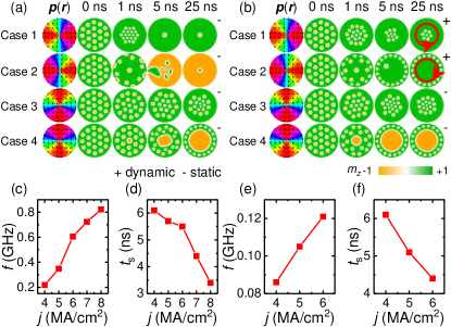
We continue to study the manipulation of a skyrmion cluster including skyrmions driven by the spin current with the spatially varied polarization. The behaviors and the final states of the skyrmion cluster are given in Fig. 3. In Fig. 3(a), is . For case 1, the radially inward driving force and the repulsion between skyrmions result in the destruction of skyrmions and only one single skyrmion centered at the nanodisk survives. In case 2, the skyrmions are rapidly expelled out of the nanodisk except for the center one. Then, the center one is expanded and transformed to become multiple domains. Eventually, a skyrmion with a core pointing the direction is formed at the center of the nanodisk. It remains as a static state. For case 3, the skyrmion cluster is compressed toward the nanodisk center. Some of skyrmions in the nanodisk center shrink and are destroyed due to the strong repulsion between the skyrmions. For this case, there are skyrmions left at ns. In the final static state at ns, we find that skyrmions remain. In case 4, the skyrmion in the center expands and other skyrmions move radially outward. At last, the skyrmion in the center is expanded significantly and others are driven toward the boundary and distributed uniformly along the nanodisk edge.
The large damping coefficient () results in a dynamic steady state for case 1 and 2, as shown in Fig. 3(b). For case 1, the skyrmions move toward the nanodisk center and some of them are destroyed due to the spiral inward driving force and repulsion between skyrmions. We find skyrmions are left with skyrmions moving around the center one. In case 2, skyrmions are driven towards the boundary. Because the space is limited, one skyrmion is expelled out the nanodisk. The other skyrmions are distributed uniformly along the edge and driven into clockwise circular motion, settling into a steady dynamic state. For cases 3 and 4, the results are similar to these in Fig. 3(a). The static states are obtained. For case 1 and 2 in Fig. 3(b) where the dynamic stable states are obtained in the end, the frequency and starting time of the circular motion of skyrmions as functions of the current density are shown in Fig. 3(e)-(f). For the skyrmion cluster in case 1 and case 2, some skyrmions are destroyed at the beginning and then the remaining skyrmions move in a circle. The starting time is the time when the steady circular motion of remaining skyrmions occurs.
The final stable states of skyrmion clusters consisting of skyrmions driven by the spin current with vortex-like polarizations (case 3 and case 4) for various current density and damping coefficient are shown in Fig. 4. For case 3, it can be seen that the number of remaining skyrmions decreases when the applied current density is increased. For example, for , skyrmions are displaced slightly toward nanodisk center when the spin current density MA/cm2, while only one skyrmion exists when MA/cm2. More skyrmions are left in the final stable state when damping constant increases. For example, when MA/cm2, there is only one skyrmion in the final stable state for and skyrmions for . It is noteworthy that the distributions of skyrmions in the final static state are symmetric. For example, when MA/cm2, the skyrmions are arranged as hexagon lattice for .
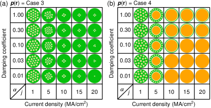
For case 4, the static final stable states for various current density and damping constant are shown in Fig. 4(b). The injection of the spin current with the polarization profile of case 4 results in the expansion of the centered skyrmion. When the applied current density is small, MA/cm2 and , the expansion of the skyrmion in the center and the displacement of the other skyrmions are small. When the current density is increased to MA/cm2, the expansion of the skyrmion in the center is obvious and the other skyrmions are pushed to the nanodisk edge. When the current density is further increased to MA/cm2, the domain with magnetization pointing down is expanded over the nanodisk. Therefore, a uniform ferromagnetic state is formed in the nanodisk. When , for MA/cm2, the driving force of the spin current and the expansion of the skyrmion at the nanodisk center erase all the other skyrmions. The expansion of the skyrmion in the center is stopped by the interaction from the edge. At last, an expanded skyrmion is obtained. When is increased to MA/cm2, the large driving force leads to a significant expansion of the domain and a uniform ferromagnetic state is obtained.
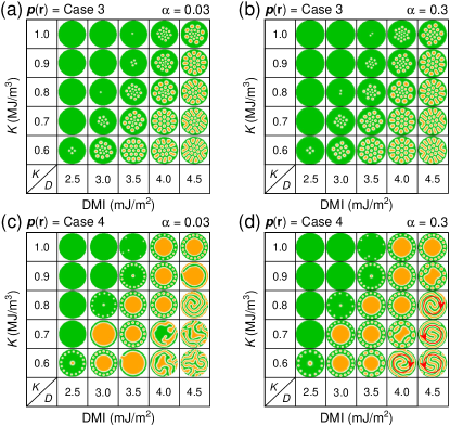
The phase diagram as functions of the DMI constant and the PMA constant at a fixed damping coefficient of or for case 3 and case 4 are shown in Fig. 5. All phase diagrams presented in Fig. 5 exhibit the single domain for the large and small since the critical DMI constant [4]. When is much smaller than , the skyrmion cannot be stabilized by the DMI in the nanodisk. For case 3, as shown in Fig. 5(a) and (b), the final stable states are static for and . The size of skyrmions increases as the DMI constant increases.
For case 4 and , when MJ/m3, the expansion of the skyrmion in the center is not significant for mJ/m2. For larger , the expansion is remarkable, as shown in Fig. 5(c). When increases to mJ/m2, the final state contains multiple domains and all skyrmions are destroyed. For case 4 and , four dynamic stable states of domain walls are found from the phase diagram, as indicated with red directed loops in Fig. 5(d), where the multiple domain walls rotate clockwise or counterclockwise driven by the spin current. Other results are static in the final stable states similar to those results in the Fig. 5(c).
IV Conclusion
We have studied the motion of magnetic skyrmions driven by spin-polarized currents with different spatially varying polarizations. The skyrmions move radically inward (case 1) or outward (case 2) when the damping is small, depending on the polarization profile. Due to the repulsions between skyrmions and edge repulsions, some of skyrmions may be destroyed and the remaining skyrmions are static in the final state. When the damping is large, the skyrmions move spirally inward (case 1) or outward (case 2) and the remaining skyrmions move in a circle in the final. The spin-polarized currents with the polarization profile of case 3 and case 4 lead to the shrink and expansion of the skyrmion cluster respectively, resulting in the deleting of skyrmions. In the final, the remaining skyrmions are static. Our results could provide a way to manipulate skyrmion clusters in future skyrmion-based devices.
Acknowledgment
X.Z. was supported by the JSPS RONPAKU (Dissertation Ph.D.) Program. G.P.Z. was supported by the National Natural Science Foundation of China (Grant Nos. 51771127, 11074179 and 10747007), and the Construction Plan for Scientific Research Innovation Teams of Universities in Sichuan (Grant No. 12TD008). W.Z. acknowledges the support by the projects from National Natural Science Foundation of China (Grant Nos. 61501013, 61571023 and 61627813), the International Collaboration Project from the Ministry of Science and Technology in China (Grant No. 2015DFE12880), and the Program of Introducing Talents of Discipline to Universities in China (Grant No. B16001). Y.Z. acknowledges the support by the President’s Fund of CUHKSZ, the National Natural Science Foundation of China (Grant No. 11574137), and Shenzhen Fundamental Research Fund (Grant Nos. JCYJ20160331164412545 and JCYJ20170410171958839).
References
- [1] I. Dzyaloshinsky, “A thermodynamic theory of "weak" ferromagnetism of antiferromagnetics”, J. Phys. Chem. Solids, vol. 4, no. 4, pp. 241–255, 1958.
- [2] T. Moriya, “Anisotropic superexchange interaction and weak ferromagnetism”, Phys. Rev., vol. 120, pp. 91–98, 1960.
- [3] U. K. Rößler, A. N. Bogdanov, and C. Pfleiderer, “Spontaneous skyrmion ground states in magnetic metals”, Nature, vol. 442, pp. 797–801, 2006.
- [4] S. Rohart, and A. Thiaville, “Skyrmion confinement in ultrathin film nanostructures in the presence of Dzyaloshinskii-Moriya interaction”, Phys. Rev. B, vol. 88, pp. 184422, 2013.
- [5] X. Z. Yu, Y. Onose, N. Kanazawa, J. H. Park, J. H. Han, Y. Matsui, N. Nagaosa, and Y. Tokura, “Real-space observation of a two-dimensional skyrmion crystal”, Nature, vol. 465, no. 7300, pp. 901–904, 2010.
- [6] N. Romming, C. Hanneken, M. Menzel, J. E. Bickel, B. Wolter, K. Bergmannvon, A. Kubetzka, and R. Wiesendanger, “Writing and deleting single magnetic skyrmions”, Science, vol. 341, no. 6146, pp. 636–639, 2013.
- [7] A. Fert, V. Cros, and J. Sampaio, “Skyrmions on the track”, Nat. Nanotech., vol. 8, no. 3, pp. 152–156, 2013.
- [8] Y. Zhou, E. Iacocca, A. A. Awad, R. K. Dumas, F. C. Zhang, H. B. Braun, and J. Akerman, “Dynamically stabilized magnetic skyrmions”, Nat. Commun., vol. 6, pp. 8193, 2015.
- [9] X. Zhang, Y. Zhou, M. Ezawa, G. P. Zhao, and W. Zhao, “Magnetic skyrmion transistor: skyrmion motion in a voltage-gated nanotrack”, Sci. Rep., vol. 5, pp. 11369, 2015.
- [10] P. Upadhyaya, G. Yu, P. K. Amiri, and K. L. Wang, “Electric-field guiding of magnetic skyrmions”, Phys. Rev. B, vol. 92, pp. 134411, 2015.
- [11] X. Zhang, M. Ezawa, and Y. Zhou, “Magnetic skyrmion logic gates: conversion, duplication and merging of skyrmions”, Sci. Rep., vol. 5, pp. 9400, 2015.
- [12] C. Reichhardt, D. Ray, and C. J. O. Reichhardt, “Magnus-induced ratchet effects for skyrmions interacting with asymmetric substrates”, New J. Phys., vol. 17, no. 7, pp. 073034, 2015.
- [13] H. Y. Yuan, and X. R. Wang, “Skyrmion creation and manipulation by nano-second current pulses”, Sci. Rep., vol. 6, pp. 22638, 2016.
- [14] X. Zhang, J. Xia, Y. Zhou, X. Liu, H. Zhang, and M. Ezawa, “Skyrmion dynamics in a frustrated ferromagnetic film and current-induced helicity locking-unlocking transition”, Nat. Commun., vol. 8, pp. 1717, 2017.
- [15] W. Kang, Y. Huang, X. Zhang, Y. Zhou, and W. Zhao, “Skyrmion-electronics: an overview and outlook”, Proc. IEEE, vol. 104, pp. 2040–2061, 2016.
- [16] G. Bourianoff, D. Pinna, M. Sitte, and K. Everschor-Sitte, “Potential implementation of reservoir computing models based on magnetic skyrmions”, AIP Adv., vol. 8, pp. 055602, 2018.
- [17] S. Mühlbauer, B. Binz, F. Jonietz, C. Pfleiderer, A. Rosch, A. Neubauer, R. Georgii, and P. Böni, “Skyrmion lattice in a chiral magnet”, Science, vol. 323, no. 5916, pp. 915–919, 2009.
- [18] S. Heinze, K. Bergmannvon, M. Menzel, J. Brede, A. Kubetzka, R. Wiesendanger, G. Bihlmayer, and S. Blugel, “Spontaneous atomic-scale magnetic skyrmion lattice in two dimensions”, Nat. Phys., vol. 7, no. 9, pp. 713–718, 2011.
- [19] S. Seki, X. Z. Yu, S. Ishiwata, and Y. Tokura, “Observation of skyrmions in a multiferroic material”, Science, vol. 336, no. 6078, pp. 198–201, 2012.
- [20] W. Jiang, P. Upadhyaya, W. Zhang, G. Yu, M. B. Jungfleisch, F. Y. Fradin, J. E. Pearson, Y. Tserkovnyak, K. L. Wang, O. Heinonen, S. G. E. Velthuiste, and A. Hoffmann, “Blowing magnetic skyrmion bubbles”, Science, vol. 349, no. 6245, pp. 283–286, 2015.
- [21] W. Jiang, X. Zhang, G. Yu, W. Zhang, X. Wang, M. Benjamin Jungfleisch, J. E. Pearson, X. Cheng, O. Heinonen, K. L. Wang, Y. Zhou, A. Hoffmann, and S. G. E. Velthuiste, “Direct observation of the skyrmion Hall effect”, Nat. Phys., vol. 13, no. 2, pp. 162–169, 2017.
- [22] J. Iwasaki, M. Mochizuki, and N. Nagaosa, “Current-induced skyrmion dynamics in constricted geometries”, Nat. Nanotech., vol. 8, pp. 742-747, 2013.
- [23] S. Woo, K. Litzius, B. Kruger, M.-Y. Im, L. Caretta, K. Richter, M. Mann, A. Krone, R. M. Reeve, M. Weigand, P. Agrawal, I. Lemesh, M.-A. Mawass, P. Fischer, M. Klaui, and G. S. D. Beach, “Observation of room-temperature magnetic skyrmions and their current-driven dynamics in ultrathin metallic ferromagnets”. Nat. Mater., vol. 15, pp. 501–506, 2016.
- [24] C. Schütte, and M. Garst, “Magnon-skyrmion scattering in chiral magnets”, Phys. Rev. B, vol. 90, pp. 094423, 2014.
- [25] X. Zhang, M. Ezawa, D. Xiao, G. P. Zhao, Y. Liu, and Y. Zhou, “All-magnetic control of skyrmions in nanowires by a spin wave”, Nanotechnology, vol. 26, no. 22, pp. 225701, 2015.
- [26] W. Wang, M. Beg, B. Zhang, W. Kuch, and H. Fangohr, “Driving magnetic skyrmions with microwave fields”, Phys. Rev. B, vol. 92, pp. 20403, 2015.
- [27] M. Beg, R. Carey, W. Wang, D. Cortés-Ortuño, M. Vousden, M.-A. Bisotti, M. Albert, D. Chernyshenko, O. Hovorka, R. L. Stamps, and H. Fangohr, “Ground state search, hysteretic behaviour, and reversal mechanism of skyrmionic textures in confined helimagnetic nanostructures”, Sci. Rep., vol. 5, pp. 17137, 2015.
- [28] Felix Büttner, C. Moutafis, M. Schneider, B. Kruger, C. M. Gunther, J. Geilhufe, C. v. Korff Schmising, J. Mohanty, B. Pfau, S. Schaffert, A. Bisig, M. Foerster, T. Schulz, C. A. F. Vaz, J. H. Franken, H. J. M. Swagten, M. Klaui, and S. Eisebitt, “Dynamics and inertia of skyrmionic spin structures”, Nat. Phys., vol. 11, pp. 225–228, 2015.
- [29] J. J. Liang, J. H. Yu, J. Chen, M. H. Qin, M. Zeng, X. B. Lu, X. S. Gao, and J.-M. Liu, “Magnetic field gradient driven dynamics of isolated skyrmions and antiskyrmions in frustrated magnets”, arXiv preprint arXiv:1712.03550, 2017.
- [30] X. Zhao, C. Jin, C. Wang, H. Du, J. Zang, M. Tian, R. Che, and Y. Zhang, “Direct imaging of magnetic field-driven transitions of skyrmion cluster states in FeGe nanodisks”, PNAS, vol. 113, no. 18, pp. 4918–4923, 2016.
- [31] L. Rózsa, A. Deák, E. Simon, R. Yanes, L. Udvardi, L. Szunyogh, and U. Nowak, “Skyrmions with attractive interactions in an ultrathin magnetic film”, Phys. Rev. Lett., vol. 117, pp. 157205, 2017.
- [32] R. A. Pepper, M. Beg, D. Cortés-Ortuño, T. Kluyver, M.-A. Bisotti, R. Carey, M. Vousden, M. Albert, W. Wang, O. Hovorka, and H. Fangohr, “Skyrmion states in thin confined polygonal nanostructures”, arXiv preprint arXiv:1801.03275, 2018.
- [33] M. Carpentieri, E. Martinez, and G. Finocchio, “High frequency spin-torque-oscillators with reduced perpendicular torque effect based on asymmetric vortex polarizer”, J. Appl. Phys., vol. 110, no. 9, pp. 093911, 2011.
- [34] F. Garcia-Sanchez, J. Sampaio, N. Reyren, V. Cros, and J.-V. Kim, “A skyrmion-based spin-torque nano-oscillator”, New J. Phys., vol. 18, no. 7, p. 75011, 2016.
- [35] M. J. Donahue, and D. G. Porter, “OOMMF user’s guide, version 1.0, interagency report NO. NISTIR 6376”, NISTIR, 1999.
- [36] S. Tacchi, R. E. Troncoso, M. Ahlberg, G. Gubbiotti, M. Madami, J. Åkerman, and P. Landeros, “Interfacial Dzyaloshinskii-Moriya interaction in films: effect of the heavy-metal thickness”, Phys. Rev. Lett., vol. 118, pp. 147201, 2017.