Undulator-Based Positron Source at 250 GeV CM Energy with Different Optical Matching Devices: Pulsed Flux Concentrator and Quarter Wave Transformer††thanks: Talk presented at the International Workshop on Future Linear Colliders (LCWS2017), Strasbourg, France, 23-27 October 2017. C17-10-23.2.
Abstract
In the baseline design of the International Linear Collider (ILC) an undulator-based source is foreseen for the positron source. In this study the energy deposition in the pulsed flux concentrator (FC) of positron source is calculated for the ILC at 250 GeV center-of-mass energy. The peak energy of 33 J/g deposited by one beam pulse in the current design of the FC is above the limit for copper material. Several promising options were considered to solve the issue of overheating the FC: the quarter wave transformer (QWT) has a significantly bigger aperture and is considered as an valuable and safe alternative for the FC. Since the positron source with a QWT is expected to lead to a lower positron capture efficiency, also the expected positron yield was calculated in addition to the energy deposition in QWT.
1 Introduction
The baseline positron source for the future International Linear Collider (ILC) is based on a superconducting helical undulator that is placed at the end of main linear accelerator [1] and produce a large amount of circularly-polarized photons hitting the target. The efficiency of positron generation in a thin titanium alloy by undulator photons depends strongly on the energy of electron drive beam passing the undulator. The average photon energy is 10.7 MeV for a 150 GeV drive beam and an undulator with 11.5 mm period and 0.86 T field on beam axis (i.e. ). The space reserved for the undulator is 231 meters. In order to get 1.5 positrons per initial electron at the damping ring (DR) for an undulator with an 150 GeV drive beam, requires an undulator magnet length of about 147 meters. One achieves a photon power of 64 kW for e-/bunch, 1312 bunches/pulse and 5 Hz pulse repetition rate.
For the center-of-mass (CM) energy of 250 GeV, i.e. for an 125 GeV electron drive beam but the same undulator parameters as for 150 GeV case, the average photon energy is 7.4 MeV. In order to get the same yield as before, 1.5 e+/e-, all 231 meters have to be used for undulator magnets. The average photon power is increased by about 10% (70.5 kW). The calculations of the positron yield have shown that the required positron current can also be achieved at 250 GeV CM energy by optimizing the positron source parameters [2, 3]. The lower energy of photons, the higher photon power and the bigger opening angle of the undulator synchrotron radiation result in the higher energy deposition in an optical matching device (OMD) downstream the target and in the accelerator structures. Therefore, at low energies, the possible issue of overheating the OMD and the accelerator structures of the capture section has to be checked carefully. The energy deposition in two different types of OMD (the pulsed FC and QWT) is considered in this paper as well.
The Geant4-based application code, PPS-Sim [4], was used for the calculations of the positron yield and for evaluating which undulator length and/or field are required to achieve the positron yield of 1.5 e+/e-. In the yield estimations, the ILC DR longitudinal acceptance () and the transverse acceptance (sum of normalized - and - emittances of 70 mmrad) were taken in account. The calculations of energy deposition and radiation damage in FC and QWT were performed in FLUKA [5].
2 Pulsed Flux Concentrator
The optical matching device (FC or QWT) is used to match the positron beam emerging from the target and characterized by small beam size and large divergence into the beam with small angular divergence and large size at the beginning capture accelerator. The FC is a pulsed tapered magnet. It was designed and prototyped at Lawrence Livermore National Laboratory. The FC has demonstrated a very good stability of fields in space and time [6]. The maximal field of the FC is 3.2 T at 2 cm from the rear side of target was used in simulations. The smallest aperture radius of the FC is 6.5 mm. The distance between Ti6Al4V target having 0.4 radiation length thickness and the 1st copper concentrating plate of the FC is 8 mm.

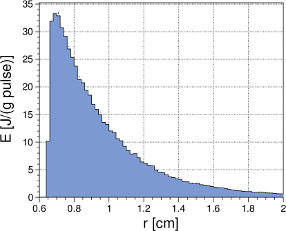
The distribution of the energy deposited by the beam in the stationary target and in the part of FC near the target is shown in the left plot of Figure 1 for the positron source with the following parameters: 125 GeV electron drive beam with 1312 bunches/pulse, 231 m undulator length with and 570 m distance between the middle of the undulator and the target. The issue of very high peak energy deposition density (PEDD) in the target is reduced to a tolerable level by the proper choice of the size and the rotation speed of the target. Taking into account that the beam heat at the target (with one meter diameter) near the outer edge and with the tangential speed of 100 m/s, the PEDD in the target is 44 J/(g pulse). The upper limits of PEDD and temperatures for the target and the OMD materials should be checked experimentally under conditions that are close to those expected at the ILC. Such experiments have already been started and first results have already been published [7, 8].
The radial profile of the energy deposited in hottest area of the FC (i.e. near the front surface) is shown in Figure 1 (right). The estimated was 33.3 J/(g pulse). This value is above the limit for copper ( J/g [9]). In order to reduce , several promising modifications of positron source parameters have been simulated [3] and are shortly summarized below:
-
1.
Using a compact electron dogleg only for the 125 GeV electron drive beam instead of the TDR dogleg, allows to shorten the distance between the middle of undulator and the target by 168.8 meters (from 569.9 m down to 401.1 m) [10]. That makes the spot size of photons on the target smaller and results in a reduction of from 33.3 J/(g pulse) down to 29.3 J/(g pulse) for a 231 m-long helical undulator with and an 125 GeV e- drive beam.
-
2.
The target thickness can be reduced to 7 mm without any losses in the positron yield [3]. It makes target cooling easier and results in approximately 8% lower .
-
3.
Taking into account the 3 GeV energy loss of the electrons along the undulator (128 GeV e- beam at beginning of undulator) and the change of the target thickness down to 7 mm results in J/(g pulse).
-
4.
In addition to the already mentioned changes, the application of a photon collimator with an aperture radius of 2.5 mm upstream target can reduce the PEDD down to 18.5 J/(g pulse).
-
5.
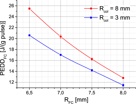
In order to reduce down to 12 J/(g pulse), the aperture radius at the beginning of the FC () has to be increased from 6.5 mm to approx. 8 mm for the case of the changes mentioned above plus a 3 mm aperture radius of the photon collimator. The dependence of on is shown in Figure 2. The Figure includes, in addition to the data for a photon collimator with mm, also the curve for mm. The photon collimator with mm has no impact on the positron yield or positron current at the DR [3], i.e. concerning the yield, such a large aperture collimator is equal to the case without collimator.
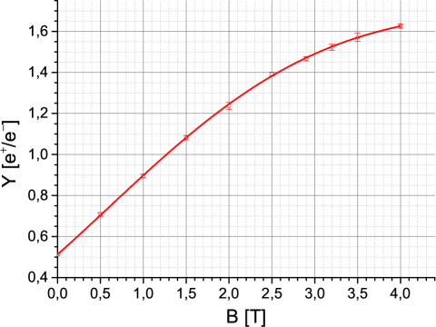
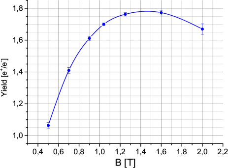
In our calculations, it was supposed, that all FC with different apertures have a 3.2 T magnetic peak field on the beam axis (). If the peak field is challenging for a FC with an 8 mm aperture radius (or larger) the will be lower and the positron yield as well. The typical dependence of the yield on at 250 GeV CM energy is shown in Figure 3. In the case that the reduction of the yield will be unacceptable low, an alternative OMD has to be used. The positron yield in the source using QWT and the energy deposition in QWT is considered below.
3 Quarter Wave Transformer
The QWT consists of two solenoids: the first one has a short length and a high magnetic field, the second one has a long length, low magnetic field superimposed on the accelerating electric field [11]. The QWT for the ILC positron source was considered by the group from Argonne National Laboratory (ANL). The estimated capture efficiency of positrons in the source using a QWT with approximately 1 Tesla first QWT magnet downstream the target was only 25% less than in the source with a pulsed FC [12]. Both OMDs were using the same 0.5 T second solenoid in which the accelerator structures were embedded. The lower field of the QWT reduces the eddy currents in the rotated target. DC QWT is easier to engineer in comparison to the FC that has to keep constant (in time and space) during 1 ms pulse the eddy currents in the volume close to the tapered aperture of FC.
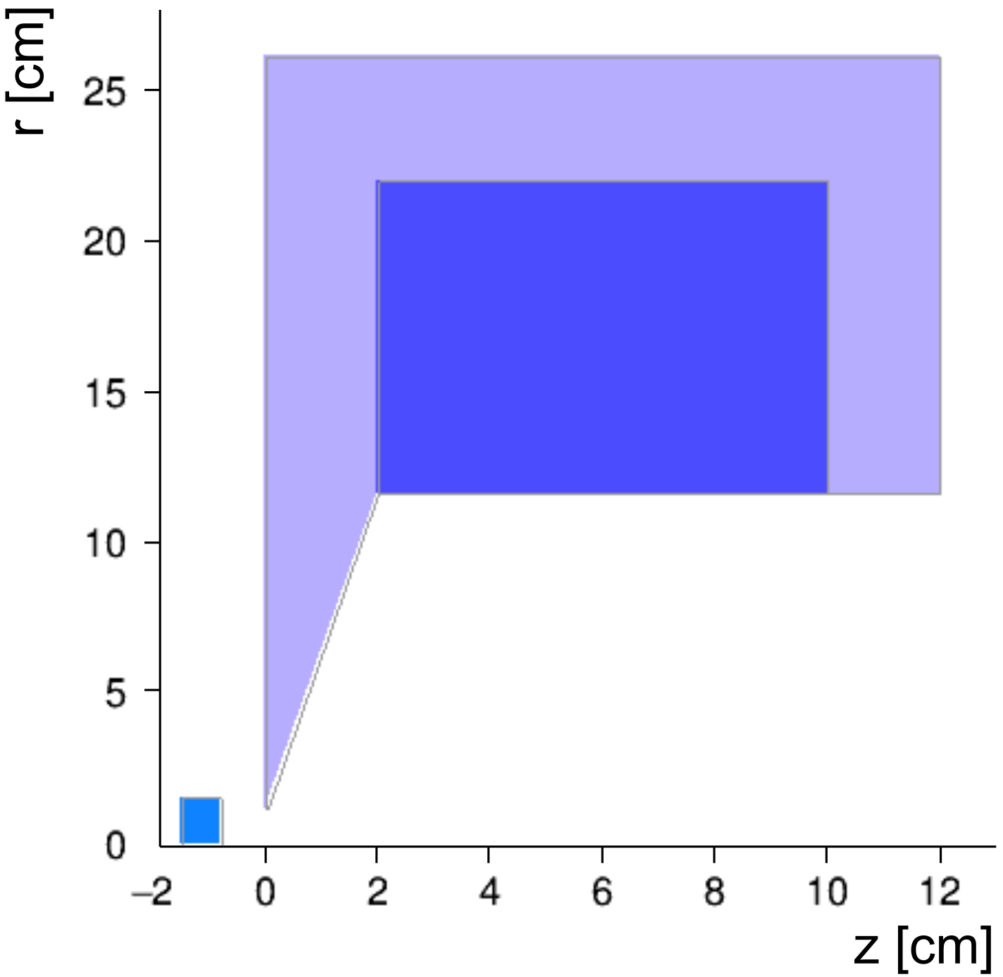
The design for the QWT considered by the ANL group was used also in our simulations. The first QWT magnet has 1.04 T field on the beam axis. It was placed 8 mm from rear side of the target. The Figure 4 shows the geometry and position of the first QWT magnet used in calculations. The coil has 8 cm length and inner radius of 11.6 cm. The tapered iron core on target side has changing radius from 1.1 cm to 11.6 cm in 2 cm in beam direction. The free space between 1.04 T and 0.5 T solenoids was 4 cm.
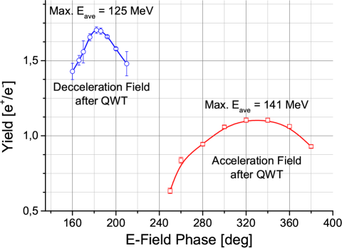
The proper choice of the electric field phase at the beginning of capture section has a big impact on the captured positron yield . The dependence of on the -field phase is shown in Figure 5 for the case of 250 GeV CM energy, TDR electron dogleg, 231 m undulator length with and 7 mm target thickness. The deceleration of positrons after the QWT helps to increase significantly.
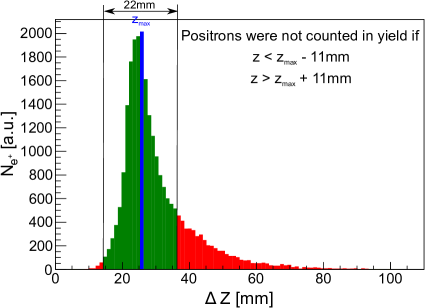
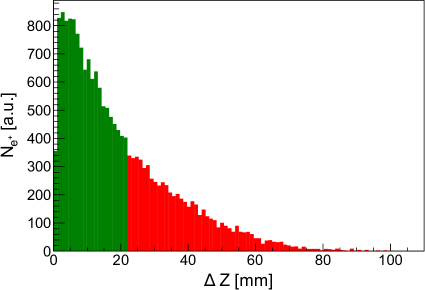
The longitudinal profile of the positron density in the bunches at the end of the capture section (125 MeV) in case of decelerating and accelerating electric fields is shown in Figure 6. It indicates that the deceleration of positrons downstream the QWT results in a smaller bunch length. The energy spread of positron beam is correlated with the bunch length. The ILC energy acceptance of the damping ring (DR) is %. An energy compressor system (ECS) is foreseen in ILC TDR and it is located downstream 5 GeV positron booster in the positron-linac-to-ring part of source beam line together with a spin rotator. According to the table with positron source parameters [13], the ECS is able to reduce the relative energy spread from 4.4% to 1.5%. The relation between the energy spread and the bunch length can be described as , where is the RF frequency and is the speed of light. An energy spread of % corresponds to mm of the bunch length. The resulting fraction of positrons counted in the positron yield (green color in Figure 6) has a full width of 22 mm.
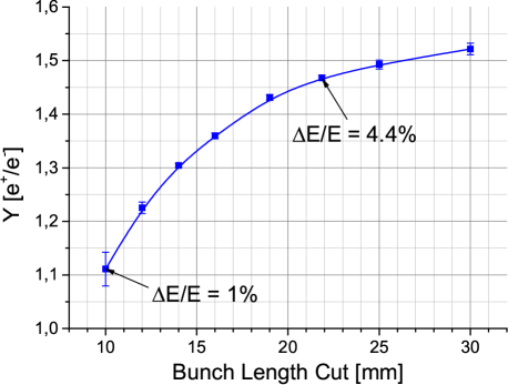
The impact of different bunch length cuts applied at the end of capture linac (125 MeV) on the positron yield is shown in Figure 7. The relative energy spread of 1% corresponds to mm. The 3.5 times energy compression was proposed by Y. Batygin [14]. In our calculation of the capture yield, the more conservative compression from 4.4% to 1.5% was supposed and the bunch length cut of 22 mm was applied at the end of capture section in addition to the 70 mmrad for the sum of normalized - and - emittances.
The dependence of the positron yield on the maximal field of the 1st QWT solenoid is shown in Figure 8. The optimal field for the 12 cm total length of 1st solenoid is approximately 1.4 T. The positron yield for the suggested 1.04 T QWT field is only a few percent less than at 1.4 T.
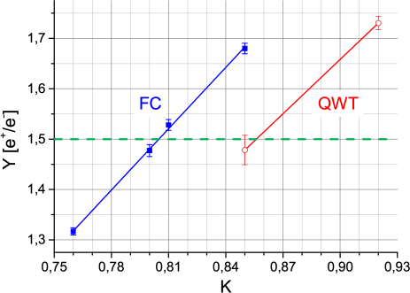
The yield of the positron source with a 3.2 T FC and a 1.04 T QWT for a 231 m long helical undulator but different undulator values is shown in Figure 9. For undulators with higher values, higher number of photons are generated (). The efficiency of the positron capture in case of using a FC is higher, but, the yield of 1.5 e+/e- for the source at 250 GeV CM energy can be achieved with a QWT too via a moderate increase of the undulator value from 0.8 to 0.85.
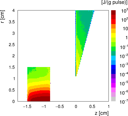
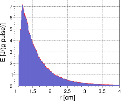
The significantly bigger aperture size of the QWT in comparison to the FC (i.e. 11 mm in QWT vs 6.5 mm in FC) for approx. the same 8 mm distance between the OMDs and the target leads to a large difference in the PEDD in the OMDs. The energy distribution and PEDD in the QWT are shown in Figure 10. The PEDDQWT in an iron yoke of the 1st solenoid is 7 J/(g pulse). The upper limit per pulse for the ARMCO Pure Steel is 12.5 J/g. The limit was estimated on the base of a simplified approach used in TESLA FEL report [9]. The finite element method calculations are needed for the engineering design of the QWT.
The distribution of the radiation damage in the QWT is very similar to the distribution of the energy deposition by the beam. The peak value of displacements per atom after 5000 hours of source operation is 0.12 dpa. It was estimated in FLUKA for room temperature. If the 0.5 dpa can be considered as an upper limit for the damage, then the QWT can be used several years without issues.
4 Summary
The positron generation and capture in the undulator-based source at 250 GeV CM energy were simulated. Two different positron matching devices (a pulsed FC and a QWT) downstream the target were considered. The issue of a too high peak energy deposition in the 3.2 T FC can be reduced down to 12 J/(g pulse) by simply increasing the aperture radius from 6.5 mm to 8 mm in case of using the compact electron dogleg, the ILC baseline undulator value of 0.8 and the photon collimator with an aperture radius of 3 mm upstream to the 7 mm thick Ti6Al4V target. The required positron yield of the positron source with 1.04 T QWT can be achieved by increasing the undulator value to 0.85. The PEDD in the QWT is 7 J/(g pulse), that is below the limit for iron yoke (12.5 J/g, ARMCO Pure Steel). The peak annual radiation damage of QWT is at relatively safe level of 0.12 dpa.
5 Acknowledgments
This work was supported by the German Federal Ministry of Education and Research, Joint Research Project R&D Accelerator “Positron Sources”, Contract Number 05H15GURBA.
References
- [1] The International Linear Collider Technical Design Report 2013, Vol. 3 - Accelerator.
- [2] A. Ushakov et al., “Simulations of the ILC positron source at low energies”, 4th International Particle Accelerator Conference (IPAC13), Shanghai, China, 12-17 May 2013, pp. 1562-1564, TUPME003.
- [3] A. Ushakov, “Energy deposition in flux concentrator by undulator photons at 250 GeV center-of-mass energy”, Americas Workshop on Linear Colliders 2017 (AWLC17), 26-30 June 2017, SLAC National Accelerator Lab, USA, slides.
- [4] A. Ushakov, S. Riemann, and A. Schälicke, “Positron source simulations using Geant4”, 1st International Particle Accelerator Conference (IPAC10), Kyoto, Japan, May 2010, pp. 4095-4097, THPEC023.
- [5] A. Fassò et al., “FLUKA: a multi-particle transport code”, CERN-2005-10 (2005), INFN/TC-05/11, SLAC-R-773.
- [6] J. Gronberg et al., “Design and prototyping of the ILC positron target system”, International Workshop on Future Linear Colliders (LCWS12), 22-26 October 2012, University of Texas at Arlington, USA, slides.
- [7] A. Ushakov et al., “Material tests for the ILC positron source”, 8th International Particle Accelerator Conference (IPAC’17), Copenhagen, Denmark, 14-19 May 2017, pp. 1293-1295, TUPAB002.
- [8] S. Riemann et al., “Target material tests with the e- beam at MAMI”, Americas Workshop on Linear Colliders 2017 (AWLC17), 26-30 June 2017, SLAC National Accelerator Lab, USA, slides.
- [9] M. Maslov, M. Schmitz and V. Sychev, “Layout considerations on the 25 GeV / 300 kW beam dump of the XFEL project”, August 2006, 72 p., DESY, TESLA-FEL 2006-05.
- [10] T. Okugi, “Compact dog-leg design for 125 GeV electron beam”, Positron Working Group Meeting, 15 March 2017, slides.
- [11] R. Chehab, “Angular collection using solenoids”, Nuclear Instruments and Methods in Physics Research A 451 (2000) pp. 362-366, doi:10.1016/S0168-9002(00)00408-3.
- [12] Wanming Liu and Wei Gai, “Update on ILC Positron source study at ANL”, International Linear Collider Workshop 2010 (LCWS10), 26-30 March 2010, Beijing, China, slides
- [13] ILC Positron Source Parameters, ILC Document, EDMS D*0943695
- [14] Y. Batygin, “Spin rotation and energy compression in the ILC Linac-to-Ring positron beamline”, Nuclear Instruments and Methods in Physics Research Section A 570, pp. 365-373 (2007), doi:10.1016/j.nima.2006.10.176